Table of Contents
Advertisement
O
'
M
perator
s
anual
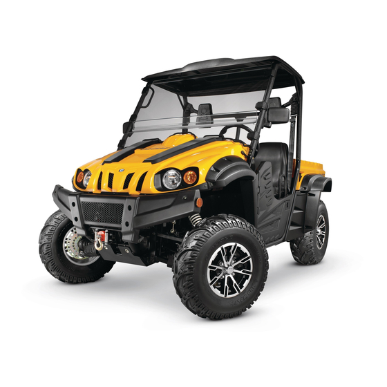
Challenger 500\700
WARNING
READ AND FOLLOW ALL SAFETY RULES AND INSTRUCTIONS IN THIS MANUAL BEFORE ATTEMPTING TO OPER-
ATE THIS MACHINE. FAILURE TO COMPLY WITH THESE INSTRUCTIONS MAY RESULT IN PERSONAL INJURY.
Form No. HS-01231401C
CUB CADET LLC, P.O. BOX 361131 CLEVELAND, OHIO 44136-0019
(December 4, 2017)
Advertisement
Table of Contents

Related Manuals for Cub Cadet Challenger 500


Summary of Contents for Cub Cadet Challenger 500
- Page 1 READ AND FOLLOW ALL SAFETY RULES AND INSTRUCTIONS IN THIS MANUAL BEFORE ATTEMPTING TO OPER- ATE THIS MACHINE. FAILURE TO COMPLY WITH THESE INSTRUCTIONS MAY RESULT IN PERSONAL INJURY. Form No. HS-01231401C CUB CADET LLC, P.O. BOX 361131 CLEVELAND, OHIO 44136-0019 (December 4, 2017)
- Page 2 Owner’s Manual WARNING: This symbol points out important safety instructions, which, if not followed, could endanger the personal safety and/or property of yourself and others. Read and follow all instructions in this manual before attempting to operate this machine. Failure to comply with these instructions may result in personal injury When you see this symbol, HEED ITS WARNING! WARNING: Engine Exhaust, some of its constituents, and certain vehicle components contain or...
- Page 3 Owner’s Manual INTRODUCTION Congratulations on your purchase of the Cub Cadet Challenger UTV. This Owner’s / Operator’s manual will provide you with information regarding safe operation, operational instructions, maintenance and care. Fully understanding this manual and following all of the instructions herein will provide the knowledge needed to have safe and enjoyable UTV operation.
-
Page 4: Important Manual Information
Owner’s Manual IMPORTANT MANUAL INFORMATION FAILURE TO FOLLOW THE WARNINGS CONTAINED IN THIS MANUAL CAN RESULT IN SERIOUS INJURY Particularly important information is distinguished in this manual by the following OR DEATH. notations: The Safety Alert Symbol means ATTENTION! YOUR SAFETY IS INVOLVED! Failure to follow WARNING instructions could result in severe injury or death to the machine operator, passengers, bystanders, or any person inspecting or repairing the machine. -
Page 5: Important Notice
Owner’s Manual IMPORTANT NOTICE This UTV is designed and manufactured for OFF - ROAD use only. It is illegal and unsafe to operate this UTV on any public street, road or highway. This UTV complies with all applicable OFF - ROAD noise level and spark arrester laws and regulations in effect at the time of manufacture. -
Page 6: Table Of Contents
Owner’s Manual Location of the Warning and 4-14 Accelerator Pedal Specification Labels 4-15 Brake Pedal Parking Brake Lever 4-16 Safety Information 4-17 Drive Select Lever 4-17 Fuel Tank Cap Description and Vehicle 4-18 Seats Identification 4-19 Seat Belts Identification Number Records 4-21 Glove Compartment Vehicle Identification Number... - Page 7 Owner’s Manual Tire Wear Limit Brake Fluid Level Brake Fluid Leakage Operation Brake Operation Starting the Engine in Low Fuel Temperatures Gasohol Starting the Engine Engine Oil Warming Up Coolant Drive Select Lever Operation and Final Gear Oil Driving In Reverse Differential Gear Oil Parking Throttle Pedal...
- Page 8 Owner’s Manual Braking To Check the Engine Oil Level 8-13 Going Uphill To Change the Engine Oil 8-14 Going Downhill 7-10 Final Gear Oil 8-17 Crossing Through Shallow Water 7-12 Checking the Final Gear Oil Level 8-17 Riding Over Rough Terrain 7-15 Changing the Final Gear Oil 8-18...
- Page 9 8-50 Headlight Beam Adjustment Owner’s Manual Tail/Brake Light Bulb Replacement 8-51 Front Brake Pad Check 8-33 Troubleshooting 8-53 Rear Brake Pad Check 8-34 Solution to Common Problems in the Checking the Brake Fluid Level 8-34 Vehicle 8-54 Brake Fluid Replacement 8-35 8-35 Checking the Brake Pedal...
- Page 10 Location of the Warning and Safety Labels Read and understand all of the labels on your vehicle. They contain important information for safe and proper operation of your vehicle. Never remove any labels from your vehicle. If a label becomes difficult to read or comes off, a replacement label is available by contacting your dealer.
- Page 11 Location of the Warning and Safety Labels Chongqing Huansong Science And Technology Industrial Co.,Ltd: A .W..,.A..,R..,N l..,N...,.G This structureme e t s ROPSr q u i r emen ts for ----t earth-moving machinery under ISO 3471. •Keep hands and body safely away when closing bed..
- Page 12 Location of the Warning and Safety Labels AWARNING: Cert1f1es this ROV complies with theAmencan National Standard • EXHAUST FUMES MAY CAUSE HARM Recreational Off-Highway Vehicles, ANSI/ROHVA 1-2011 Standard Engine exhaust from this product contains chemicals, known in certain TYPE VEHICLE quantities to cause cancer, birth defects, or other...
- Page 13 Location of the Warning and Safety Labels WARNING •Improperly loading trailer and failure to • Max towing weight:544kg(1200Ibs extra care when pulling trailer can cause an accident or injury. • Max tongue weight:50kg( 11Olbs) • Never load more than 1101b (50kg) tongue weight on the towing bracket.
- Page 14 Location of the Warning and Safety Labels AWARNING • • Turn speed not to exceed 18 MPH/30 KPH Do not drive in the water deeper than 15 4--- -- '--- I NG Operation takes more effort whil e the veh icle -LOCK.
-
Page 15: Safety Information
Safety Information Operation General Operation Read, understand, and follow all instructions on the vehicle and in the manual before attempting to operate or service vehicle. Keep this manual in a safe place for future and regular reference and for ordering replacement parts. This is an off-road utility vehicle and it should not be operated on public highways. - Page 16 Safety Information Never allow children under 16 years old to operate this vehicle. Children 16 years old and over should read and understand the operation instructions and safety rules in this manual and should be trained and supervised by a parent. Watch for traffic when operating near or crossing roadways.
- Page 17 Safety Information Inspect area around vehicle before moving, especially in reverse. Back up slowly. Always look down and behind before and while backing to avoid a back-over accident. Keep bystanders out of area. Avoid driving through water, since loss of control may occur. Drive belt may slip if exposed to water thus reducing vehicle pulling power and stopping vehicle entirely.
- Page 18 Safety Information Use the operator protective structure (OPS) and seat belt for safe operation. Overturning the utility vehicle without an operator protective structure (OPS), or with an operator protective structure (OPS) and the seat belt unfastened, can result in death or injury.
- Page 19 Safety Information Assure safety interlock switch is adjusted correctly so engine cannot be started unless gearshift is in the neutral position. Do not touch engine or muffler while engine is running or soon after it is stopped. They will be hot and can cause a burn. Always inspect your vehicle each time you use it to make sure it is in safe operating condition.
- Page 20 Safety Information Dress Properly Slope Operation...
- Page 21 Safety Information Avoid slopes with slippery, loose, or bumpy surfaces as they are especially hazardous. Use extra care while carrying cargo.It may affect the stability of the vehicle. Spread the load evenly or tie down. Do Not: Do not travel near drop-offs, ditches or embankments. The vehicle could suddenly overturn if a wheel is over the edge of a cliff, ditch, or if an edge caves in.
- Page 22 Safety Information Cargo Box Loading/Operation...
- Page 23 Safety Information Avoid sudden starts, stops, and turns which could cause load to shift. Cargo Box Lift Stop vehicle on level ground and set Parking Brake before raising cargo box. On manual lift units, unload cargo box before raising cargo box. Do not operate vehicle with cargo box in raised position.
- Page 24 Never attempt to straighten or re-weld any part of the main frame or retaining brackets that have been damaged. Doing so may weaken the structure and endanger your safety. Never secure any parts other than Cub Cadet approved accessories on the main frame or attach the safety frame with anything other than the special fasteners specified.
- Page 25 Safety Information 2-11 Keep children out of the immediate area of the vehicle and in watchful care of a responsible adult other than the operator. Be alert and turn the vehicle off if a child enters the area. Before and while backing, look behind and down for small children. Never carry small children, they may fall off and be seriously injured or interfere with safe vehicle operation.
- Page 26 2-12 Safety Information Safe Handling Of Fuel:...
- Page 27 Safety Information 2-13 Keep the nozzle in contact with the rim of the fuel tank or container opening at all times until fueling is complete. Do not use a nozzle lock-open device. Extinguish all cigarettes, cigars, pipes and other sources of ignition. Never fuel machine indoors.
- Page 28 2-14 Safety Information General Service Never run an engine indoors or in a poorly ventilated area. Engine exhaust contains carbon monoxide, an odorless, and deadly gas. Before cleaning, repairing, or inspecting, make certain all moving parts have stopped. Disconnect the spark plug wires and ground against the engine to prevent unintended starting.
- Page 29 Safety Information 2-15 Maintain or replace safety and instruction labels, as necessary. According to the Consumer Products Safety Commission (CPSC) and the U.S. Environmental Protection Agency (EPA), units in this product category have an Average Useful Life of seven (7) years, or approximately 400 hours of operation. To extend the life of your unit, and specifically after (7) years of ownership or at 400 hours of operation, have the unit inspected annually by an authorized service dealer to ensure that all mechanical and safety systems are working properly and not worn excessively.
- Page 30 2-16 Safety Information DO NOT pour oil or other fluids into the ground, down a drain or into a stream, pond, lake or other body of water. Observe Environmental Protection Agency regulations when disposing of oil, fuel, coolant, brake fluid, filters, batteries, tires and other harmful waste.
-
Page 31: Spark Arrestor
Safety Information 2-17 Gasoline powered products may be equipped with the following emission control systems: Please contact Customer Support for information regarding the evaporative emission control configuration for your model. Spark Arrestor WARNING: This unit is equipped with an internal combustion engine and should not be used on or near any unimproved forest-covered, brush-covered or grass-covered land unless the engine's exhaust system is equipped with a spark arrestor meeting applicable local or state laws (if any). - Page 32 2-18 Safety Information...
-
Page 33: Description And Vehicle Identification
Description and Vehicle Identification Headlights Spark arrester Front shock absorber assembly adjusting ring Passenger seat belt Brake fluid reservoir Passenger seat Air filter element(engine and air intake duct) Oil filter cartridge V-belt case Engine oil dipstick Driver seat Battery Driver seat belt Fuses Spark plug Coolant reservoir... - Page 34 Description and Vehicle Identification Light switch Steering wheel Starter Main switch On-Command four-wheel-drive and differential lock switches Multi-function meter unit Auxiliary DC jack Drive select lever Parking brake lever Accelerator pedal Brake pedal NOTE: The vehicle you have purchased may differ slightly from those in the figures of this manual.
-
Page 35: Identification Number Records
Description and Vehicle Identification Identification Number Records Vehicle Identification Number Record the Vehicle Identification Number and The Vehicle Identification Number (VIN) is model label information in spaces provided for stamped into the frame. assistance when ordering spare parts from a service center or for reference in case the vehicle is stolen. -
Page 36: Control Functions
Control Functions 6. Emergency light button CONTROL FUNCTIONS ● Set the switch to ”,to turn on the low Combination switch beam。 ● Set the switch to Light switch ” ”,to turn on the high beam。 ● Set the switch to “OFF” to turn off all the lights.。... -
Page 37: Main Switch
Control Functions Main switch KEY: Turning the steering wheel can lock the steering wheel direction and the key can be removed. START: The electric starter is engaged by turning and holding the key in this position. Release the key when the engine starts. 1. -
Page 38: Indicator And Warning Lights
Control Functions Indicator and Warning Lights See starting instructions prior to starting ● the engine. (See pages 6-1 - 6-3 for details.) Horn switch Four-wheel drive lock indicator light EPS System Fault indicator light Differential gear lock indicator Coolant temperature warning light 1.Horn switch button Hazard light indicator Press this button to activate the horn. - Page 39 Control Functions Reverse Indicator Light “R” Low-Range Indicator Light “L” This indicator light comes on when the drive This indicator light comes on when the drive select lever is in the “R” reverse position. select lever is in the “L” position. Coolant Temperature Warning Light ”...
-
Page 40: Speedometer Unit
Control Functions Speedometer Unit is out. Continuous use while the light is on may cause damage to the engine. High beam indicator The light being on means headlight is at high beam mode. Position light indicator The light being on means that the position light fixed in the front headlight has been turned on. -
Page 41: Odometer And Trip Meter Modes
Control Functions Speedometer unit functions include: from the odometer, to the tripometer, and a speedometer (which shows the speed) then to the hours meter; then it starts the an odometer (which shows the total cycle over. distance covered) The odometer displays the total distance ... - Page 42 Control Functions button on the display. This will also change displayed mileage from miles Four-wheel drive indicator ” kilometers. There are two 4WD indicators on the display Clock time adjustment panel. The left 4WD indicator has a blinking Press the left button and hold for three circle on the front axle when the unit is in seconds and the clock goes into the hour 4WD.
-
Page 43: Fault Code Indicator
Control Functions unit must in in 4WD mode. The level is then CAUTION: moved to expose the Yellow differential lock When the selector is set to 4WD and Locked button. The Yellow button must be pushed Differential, the right 4WD symbol front axle and in the out position for the rear differential will have an ‘X’... -
Page 44: Fuel Level Indicator
Control Functions send the fault code to the instrument display, and it will flash on the clock. If there is more than one fault code, they will be shown in a rolling sequence. When fault codes are present, in order to see the time press the clock button, the time will be shown. - Page 45 4-10 Control Functions Switches battery may discharge to the point that the starter motor will not operate properly. If this happens, remove the battery and recharge it. On-Command Four-Wheel–Drive and Differential Gear Lock Switches 1. Light switch “OFF/ ” Light switch ”...
- Page 46 Control Functions 4-11 This vehicle is equipped with an On-Command four–wheel-drive switch WARNING “2WD”/ “4WD”and a differential gear lock POTENTIAL HAZARD Changing from 2WD to 4WD or from 2WD switch “4WD”/ “LOCK”. Select the to 2WD-Differential UNLOCK, or appropriate drive according to terrain and the vice-versa while the vehicle is moving.
- Page 47 4-12 Control Functions the select lever is set to position , and On-Command four-wheel-drive switch then set the switch to “2WD”. “2WD/4WD” On-Command Differential Gear Lock Switch “4WD”/”LOCK” Select lever On-Command four –wheel-drive switch “2WD/4WD” To change from 2WD to 4WD ,stop the vehicle, and then set the switch to On-Command differential gear lock switch “4WD”/ “LOCK”...
- Page 48 Control Functions 4-13 set the switch to “LOCK”. When the differential gear is locked, the differential HOW TO AVOID THE HAZARD gear lock indicator light will come on along Always ride at a slow speed when the with the differential gear lock indicator in the multifunction meter unit display .To release vehicle is in 4WD-LOCK, and allow extra the differential gear lock , stop the vehicle...
-
Page 49: Accelerator Pedal
4-14 Control Functions indicator and indicator light are flashing) will cause the engine speed to be limited until engagement is complete. Accelerator pedal Press the accelerator pedal down to increase engine speed. Spring pressure returns the pedal to the rest position when released. 1. -
Page 50: Brake Pedal
Control Functions 4-15 WARNING POTENTIAL HAZARD Malfunction of the accelerator pedal. WHAT CAN HAPPEN A faulty pedal that makes it difficult to speed up or slowdown could cause loss of control. HOW TO AVOID THE HAZARD Check the operation of the accelerator pedal before you start the engine .If it 1. -
Page 51: Parking Brake Lever
4-16 Control Functions push the lever all the way down. Spring The drive select lever is used to shift your vehicle into the low, high, neutral and reverse pressure helps return the lever to the positions. (Refer to pages 6-4—6-6 for the released position. -
Page 52: Fuel Tank Cap
Control Functions 4-17 Remove the fuel tank cap by turning it Seats counterclockwise. To remove a seat, pull its seat lock lever upward, lift the front of the seat, and then slide the seat forward and up. 1. Fuel tank cap 1. -
Page 53: Seats
4-18 Control Functions To install a seat, insert the projection on the rear of the seat into the seat holders and push down on the seat at the front. WARNING POTENTIAL HAZARD A loose seat. WHAT CAN HAPPEN The operator could lose control or the operator or passenger could fall if the seat is loose during operation. -
Page 54: Seat Belts
Control Functions 4-19 2. Push the latch plate into the buckle until it clicks. Pull up on the latch plate to make sure it is secure. Seat belt (×2) 2. Latch plate (×2) 3. Buckle (×2) To wear the seat belt properly, do the 1. - Page 55 4-20 Control Functions shoulder belt should fit against your chest. If it is loose, pull the belt out all the WARNING way and then let it retract. POTENTIAL HAZARD 5. To release the buckle, firmly press the Not wearing the seat belt or wearing the release button.
-
Page 56: Glove Compartment
Control Functions 4-21 Glove compartment Cargo bed CAUTION: To protect from damage, do not put metal products, like tools or sharply edged products directly in the glove compartment. If they must be stored, wrap them in appropriate cushion material. 1. Cargo bed 2. -
Page 57: Cargo Bed
4-22 Control Functions Opening and closing the tailgate Lifting and lowering the cargo bed 1. Tailgate 2. Latch (×2) 1. Cargo bed release lever To lift To open Push down cargo bed release lever on left or Unhook the latches, and then lower the right side of the vehicle;... - Page 58 Control Functions 4-23 WARNING WARNING POTENTIAL HAZARD POTENTIAL HAZARD Overloading the cargo bed Pinch points. WHAT CAN HAPPEN WHAT CAN HAPPEN Could cause changes in vehicle handling You or someone else could be pinched which could lead to an accident. between the cargo bed and the frame HOW TO AVOID THE HAZARD when the bed is being lowered.
-
Page 59: Front And Rear Shock Adjustment
4-24 Control Functions Front and Rear Shock Adjustment(Option 1) The spring preload can be adjusted to suit WARNING the operating conditions. POTENTIAL HAZARD You can reduce preload for a softer ride, or Carrying a passenger in the cargo bed increase preload if frequent bottoming out of WHAT CAN HAPPEN the UTV occurs. - Page 60 Control Functions 4-25 Standard position: B A-Minimum(soft) E-Maximum(hard) 1. Special wrench 1. Spring preload adjusting ring 2. Position indicator NOTE: A special wrench can be obtained at a service center to make this adjustment.
- Page 61 4-26 Control Functions Front and Rear Shock Adjustment(Option 2) WARNING WARNING POTENTIAL HAZARD These shock absorber assemblies Improper shock absorber adjustment. contain highly pressurized nitrogen gas, read understand following WHAT CAN HAPPEN Uneven adjustment can cause poor information before handling the shock absorber assemblies.
- Page 62 Control Functions 4-27 Spring preload · 1. Loosen the locknut. Do not dispose of a damaged or worn out shock absorber assembly yourself. 2. Turn the spring preload adjusting nut in direction ⓐ to increase the spring Take the shock absorber assembly to an preload thereby harden...
-
Page 63: Spring Preload
4-28 Control Functions · A special wrench can be obtained at an authorized dealer to make this adjustment. Spring travel setting(Front) · The spring preload setting is determined Minimum(soft): 412mm(16.22 in) by measuring distance A, shown in the Maximum(hard): 426mm(16.77 in) illustration. -
Page 64: Rebound Damping Force
Control Functions 4-29 damping, and in direction F to decrease the Compression damping force rebound damping force and thereby soften Turn compression damping force the damping. adjusting screw (use 3.0 allen wrench) in direction ⓐ to increase the compression damping force and thereby harden the damping, and in direction ⓑ... -
Page 65: Compression Damping Force
4-30 Control Functions Trailer hitch bracket This vehicle is equipped with a 1 ¼ in WARNING receiver bracket for a standard trailer hitch. · Suspension components become hot Trailer towing equipment can be obtained at during operation. Never touch a service center. (See pages 6-12 - 6-14 for compression damping force adjusting precaution information.) screw,... -
Page 66: Auxiliary Dc Jack
Control Functions 4-31 Auxiliary DC jack The auxiliary DC jack is located at the right side of the front panel. The auxiliary DC jack can be used for suitable work lights, radios, etc. The auxiliary DC jack should only be used when the engine is running. - Page 67 4-32 Control Functions 4. When the auxiliary DC jack is not being used, cover it with the cap. CAUTION: Do not use accessories requiring more than the above maximum capacity. This may overload the circuit and cause the fuse to blow. ...
-
Page 68: Pre Operation Checks
Pre Operation Checks Before using this vehicle, check the following items: ITEM ROUTINE PAGE Check operation, free play, fluid level and fluid leakage ● Brakes 5-2 - 5-3, 8-35 Fill with DOT 4 brake fluid if necessary ● Check for proper operation, condition and free play ●... -
Page 69: Brakes
Pre Operation Checks WARNING Brakes Check for correct brake pedal free play. If the POTENTIAL HAZARD brake pedal free play is incorrect, have a Failure to inspect the vehicle before service center adjust it. (See pages 8-37 - operating. Failure to properly maintain the 8-38.) vehicle. -
Page 70: Brake Fluid Leakage
Pre Operation Checks Brake fluid leakage Check to see if any brake fluid is leaking out of WARNING the hydraulic brake lines, fittings, or the brake POTENTIAL HAZARD fluid reservoir. Apply the brakes firmly for one Driving with improperly operating brakes. minute. -
Page 71: Fuel
Pre Operation Checks Fuel Make sure there is sufficient gasoline in the Your engine has been designed to use regular tank. unleaded gasoline with a pump octane number ([R+M] /2) of 91 or higher, or research octane Recommended fuel: number of 91 or higher. If knocking or pinging Unleaded Non Ethanol 91 Octane or occurs, use a different brand of gasoline or higher gasoline only. -
Page 72: Engine Oil
Pre Operation Checks WARNING Engine oil POTENTIAL HAZARD Make sure the engine oil is at the specified level. Improper care when refueling. Add oil as necessary. (See pages 8-12) WHAT CAN HAPPEN Fuel can spill, which can cause a fire and CAUTION: severe injury. -
Page 73: Coolant
Pre Operation Checks Recommended engine oil type and CAUTION: quantity: Hard water or salt water is harmful to the engine. See page 11-2 You may use soft water if you cannot get distilled water. Coolant Check the coolant level in the coolant reservoir Coolant reservoir capacity when the engine is cold. -
Page 74: Final Gear Oil
Pre Operation Checks WARNING Final gear oil Make sure the final gear oil is at the specified POTENTIAL HAZARD level. Add oil as necessary. (See pages 8-17 - Removing the radiator cap when the engine 8-18 for details) and radiator are still hot. WHAT CAN HAPPEN Recommended oil: You could be burned by hot fluid and steam... -
Page 75: Throttle Pedal
Pre Operation Checks WARNING Throttle Pedal Failure to check or maintain proper Check to see that the accelerator pedal operation of the throttle system can result in operates correctly. It must operate smoothly an accident and lead to serious injury or and fully spring back to the idle position when death if the throttle pedal sticks during released. -
Page 76: Throttle Freeplay
Pre Operation Checks Throttle Freeplay Inspection 1. Set the parking brake . 2. Apply the brakes. Start the engine. Allow it to warm up thoroughly. 3. Measure the distance the throttle pedal moves before the engine begins to pick up speed. -
Page 77: Seat Belts
5-10 Pre Operation Checks 2. Lightly turn the steering wheel left and right. system and the OPS structure for integrity. 3. There should be 0.8″-1.0″ (20-25 mm) of freeplay. Fittings and fasteners Always check the tightness of chassis fittings If there is excessive freeplay, unusual noises, or the steering feels rough or″catchy, ″have the and fasteners before a ride. - Page 78 Pre Operation Checks 5-11 Tires WARNING 3. The tires should be set to the POTENTIAL HAZARD recommended pressure: Operating this vehicle with improper tires, Front 10psi (70kpa, 0.7 kgf/cm or with improper or uneven tire pressure. Rear 10psi (70kpa, 0.7 kgf/cm WHAT CAN HAPPEN Check and adjust tire pressures when the Use of improper tires on this vehicle, or...
-
Page 79: Specifications
5-12 Pre Operation Checks Set pressure with tires cold. Set tire pressures to the following specifications: 5. Use no more than the following pressures Recommended when seating the tire beads. Minimum Maximum Pressure Front 36psi (250kpa, 2.5kgf/cm 10psi (70kpa 9 psi (63kpa, 11 psi, (77kpa, Front Rear 36psi (250kpa, 2.5kgf/cm... - Page 80 Pre Operation Checks 5-13 Tire wear limit When the tire groove decreases to 0.12 in (3 mm) due to wear, replace the tire. a. Tire wear limit...
-
Page 81: Operation
Operation WARNING WARNING POTENTIAL HAZARD POTENTIAL HAZARD Operating vehicle without being familiar Freezing control cables due to cold weather conditions. with all controls. WHAT CAN HAPPEN WHAT CAN HAPPEN Loss of control, which could cause an Loss of vehicle control, which could lead to an accident or collision. -
Page 82: Drive Select Lever
Operation indicator light does not come on, ask a Starting the Engine service center to inspect the electric CAUTION: circuit. See the “Engine Break-In”section prior to The engine can be started in any gear if ● operating the engine for the first time. the brake is applied. -
Page 83: Warming Up
Operation attempt. the throttle pedal to make the engine run at 2500RPM to charge the battery for 5-10 5. Continue warming up the engine until it minutes; when the voltage of battery is over idles smoothly before riding. 12V, the idle speed will be normal. If the idle speed is still high, please contact your WARNING service center. -
Page 84: Drive Select Lever Operation And Driving In Reverse
Operation go on with the third step. Shifting: Neutral to High and High to Low 3. Continue warming up the engine until it 1. Stop the vehicle. Keep your foot off the idles smoothly. accelerator pedal. CAUTION: 2. Apply the brakes, and then shift by See the “Engine break-in”... - Page 85 Operation the shift guide. NOTE: ● Always depress the brake pedal before placing the gearshift lever to“reverse”position. ● In the brake pedal, there is a cable, which is connected to a position pin located on the gearshift assembly. Only when the brake pedal is depressed, the position pin will be retracked, and gearshifts can be removed to “reverse”...
- Page 86 Operation the engine, the light may not come on until the vehicle starts moving. 4. Check behind for people or obstacles, and then release the brake pedal. 5. Press the accelerator pedal gradually and continue to watch to the rear while backing up.
- Page 87 Operation WARNING WARNING POTENTIAL HAZARD POTENTIAL HAZARD Parking on a hill or other incline. Improperly operating in reverse. WHAT CAN HAPPEN WHAT CAN HAPPEN The vehicle could roll out of control, You could hit an obstacle or person increasing the chance of an accident. behind you, resulting in serious injury.
-
Page 88: Parking
Operation Parking Parking on a Slope a) When parking, stop the engine and shift the drive select lever into the neutral position. b) Push the brake pedal down, and pull the parking brake to top position to park the vehicle 1. -
Page 89: Vehicle Break-In Period
Operation Vehicle Break-in Period The break-in period for your new UTV vehicle is the first 25 hours of operation, or the time it takes to use the first three tanks full of gasoline. No single action on your part is as important as a proper break-in period. Careful treatment of a new engine and drive components will result in more efficient performance and longer life for these... - Page 90 Operation 6-10 momentary (2-3 seconds maximum) full of use. throttle operation under load does not harm Use of any engine oil not mentioned in ● this manual will cause severe damage to the engine. the engine. Each full throttle acceleration sequence should be followed with a substantial rest period for the engine by cruising at lower Engine Break-In...
- Page 91 6-11 Operation 10-25 Hours: performance. Break in the clutches and belt Avoid prolonged operation above 3/4 throttle. by operating at slower speeds during the Rev the vehicle freely but do not use full break-in period as recommended. Pull only throttle at any time. light loads.
- Page 92 Operation 6-12 nonstandard accessories, nor have any with accessories. The vehicle may control over the quality or suitability of handle differently than it does without them. Choose only genuine accessories, accessories. or accessories which are equivalent in design and quality. Loading Accessories should be rigidly and Cargo or a trailer can change the stability...
- Page 93 6-13 Operation weight. You can measure tongue weight MAXIMUM LOADING LIMIT with a bathroom scale. Put the tongue of Vehicle loading limit (total weight of ● cargo, operator, passenger and the loaded trailer on the scale with the accessories, and tongue weight): tongue at hitch height.
- Page 94 Operation 6-14 move around. A shifting load can cause terrain carefully. Added weight affects the an accident. stability and handling of the vehicle. Make sure the load does not interfere ● with controls or your ability to see where you are going. Drive more slowly than you would without ●...
- Page 95 6-15 Operation WARNING POTENTIAL HAZARD Overloading this vehicle or carrying or towing cargo improperly. WHAT CAN HAPPEN Could cause changes in vehicle handling which could lead to an accident. HOW TO AVOID THE HAZARD Never exceed the stated load capacity for this vehicle.
-
Page 96: Driving Your Vehicle
Your Vehicle DRIVING YOUR VEHICLE WARNING GETTING TO KNOW YOUR VEHICLE POTENTIAL HAZARD This off-highway utility vehicle will handle Not wearing the seat belt. and maneuver differently form an ordinary Wearing the seat belt improperly. passenger car or other vehicle. WHAT CAN HAPPEN Before you begin to use your vehicle, be sure There is increased risk of being killed or... - Page 97 Your Vehicle The total weight of operator, passenger, WARNING accessories, cargo, trailer tongue weight, POTENTIAL HAZARD and the vehicle itself must not exceed 1,880 Carrying a passenger in the cargo bed. lbs (853Kg). WHAT CAN HAPPEN The passenger could fall or be struck by objects in the cargo bed.
- Page 98 Your Vehicle The driver and passenger must always wear WARNING a seat belt, an approved motorcycle helmet, POTENTIAL HAZARD eye protection and protective clothing, Overloading this vehicle or carrying or including over-the-ankle boots, gloves, a towing cargo improperly. long-sleeved shirt or jacket, and long pants. WHAT CAN HAPPEN Keep hands and feet inside the vehicle at all Could cause changes in vehicle...
- Page 99 Your Vehicle WARNING HOW TO AVOID THE HAZARD POTENTIAL HAZARD Always wear an approved motorcycle Operating this vehicle without wearing an helmet that fits properly. You should also approved motorcycle helmet, eye wear: protection, and protective clothing. WHAT CAN eye protection (goggles HAPPEN or face shield) gloves Operating without...
-
Page 100: Learning To Operate Your Vehicle
Your Vehicle LEARNING TO OPERATE YOUR VEHICLE Perform the Pre-Operation Checks on pages You should become familiar with the 5-1 - 5-11. Set the parking brake, shift to performance characteristics of the vehicle in neutral, and follow the instructions on page a large, flat area that is free of obstacles and 6-1 to start the engine. -
Page 101: Turning Your Vehicle
Your Vehicle possibility of an accident. attempt to turn around or make abrupt maneuvers on slopes. Position your hands on the steering wheel so CAUTION: that your thumbs and fingers do not wrap Do not shift from low to high or vice versa around the wheel. - Page 102 Your Vehicle Follow these precautions when operating in reverse: 1. Always check for obstacles or people behind the vehicle. 2. Apply the throttle lightly. Never open the throttle suddenly. 3. Back up slowly. 4. Apply the brakes lightly for stopping. 5.
-
Page 103: Braking
Your Vehicle BRAKING Braking ability is affected by the type of terrain. In most cases, gradual application of the brakes is more effective than abrupt braking, particularly on loose surfaces like gravel. Always allow for greater braking distance on rough, loose, or slippery surfaces. - Page 104 Your Vehicle some hills are too steep for you to climb. WARNING Maximum slope angle:15° POTENTIAL HAZARD Operating on excessively steep hills. WHAT CAN HAPPEN The vehicle can over turn more easily on extremely steep hills than on level surfaces or small hills. HOW TO AVOID THE HAZARD Never operate your vehicle on hills too steep for it or your abilities.
-
Page 105: Going Downhill
7-10 Your Vehicle Before climbing the hill, first be sure you are around. With your foot on the brake, look operating in low range 2WD or, if necessary, behind you and plan your descent. Shift the with 4WD. To climb a hill, you need traction, drive select lever in reverse so you can use momentum, and steady throttle. - Page 106 Your Vehicle 7-11 Before starting downhill, make sure the you will be able to react to obstacles that may vehicle is in low-range 4WD. On most slopes, appear. this will let you use engine braking to help you go downhill slowly. Go as slowly as WARNING possible.
-
Page 107: Crossing Through Shallow Water
7-12 Your Vehicle CROSSING THROUGH SHALLOW WATER WARNING If you must cross shallow, slow moving water POTENTIAL HAZARD up to the depth of the vehicle’s floorboards, Operating this vehicle through deep or choose your path carefully to avoid sharp fast-flowing water. drop-offs, large rocks, or slippery surfaces WHAT CAN HAPPEN Loss of control, which could result in an... - Page 108 Your Vehicle 7-13 Vehicle Immersion CAUTION: CAUTION: After riding your vehicle in water, be sure to If your vehicle becomes immersed, major drain the trapped water by removing the engine damage can result if the machine is check hose at the bottom of the air filter case, the V-belt cooling duct check hose, the drive not thoroughly inspected.
- Page 109 7-14 Your Vehicle 5. Dry the spark plugs and reinstall them, or CAUTION: install new plugs. Make sure all components that are washed 6. Attempt to start the engine. If necessary, and assembled are coated lightly with repeat the drying procedure. grease.
-
Page 110: Riding Over Rough Terrain
Your Vehicle 7-15 1.V-belt cooling duct check hose 1.V-belt case drain plug Riding Over Rough Terrain Operating over rough terrain should be done with caution. Look for obstacles that could cause damage to the vehicle or could lead to a rollover accident. Avoid jumping the vehicle as injury, loss of control, and damage to the vehicle could occur. - Page 111 7-16 Your Vehicle WARNING POTENTIAL HAZARD Failure to use extra care when operating this vehicle on unfamiliar terrain. WHAT CAN HAPPEN You can come upon hidden rocks, bumps, or holes, without enough time to react. Could result in the vehicle overturning or going out of control.
-
Page 112: Riding In Brush Or Wooded Areas
Your Vehicle 7-17 thoroughly. Look from both your approach Riding in Brush or Wooded Areas side and the exit side. If you believe you can When operating in areas with brush or trees, continue safely, decide the path that will watch carefully on both sides and above the allow you to get over the obstacle at as close vehicle for obstacles such as branches that... - Page 113 7-18 Your Vehicle WARNING POTENTIAL HAZARD Improperly operating over obstacles. WHAT CAN HAPPEN Could cause loss of control or a collision. Could cause the vehicle to overturn. HOW TO AVOID THE HAZARD Before operating in a new area, check for obstacles.
-
Page 114: Periodic Maintenance And Adjustment
Periodic Maintenance and Adjustment NOTE: Periodic Maintenance and Adjustment If you do not have a torque wrench available Periodic inspection, adjustment and during a service operation requiring lubrication will keep your vehicle in the safest one, take your vehicle to service center to and most efficient condition possible. - Page 115 Periodic Maintenance and Adjustment WARNING WARNING POTENTIAL HAZARD POTENTIAL HAZARD Operating this vehicle with improper Servicing an engine while it is running. modifications. WHAT CAN HAPPEN Moving parts can catch clothing or parts WHAT CAN HAPPEN of the body, causing injury. Improper installation of accessories or Electrical components can cause shocks modification of this vehicle may cause...
-
Page 116: Periodic Maintenance Chart For The Emission Control System
Periodic Maintenance and Adjustment Periodic Maintenance Chart for the Emission Control System ● For vehicles not equipped with an odometer or hour meter, follow the month maintenance intervals. ● For vehicles equipped with an odometer or an hour meter, follow the mile (km) or hours maintenance intervals. However, keep in mind that if the vehicle is not used for a long period, the month maintenance intervals should be followed. -
Page 117: General Maintenance And Lubrication Chart
Periodic Maintenance and Adjustment General maintenance and lubrication chart INITIAL EVERY Month Whichever ITEM ROUTINE Miles 1,500 1,500 3,000 Comes first (320) (2,400) (2,400) (4,800) (Km) (1,200) hours Check coolant leakage. ● ○ ○ ○ Repair if necessary. ○ ○ Cooling system ●... - Page 118 Periodic Maintenance and Adjustment INITIAL EVERY Month Whichever ITEM ROUTINE Miles 1,500 1,500 3,000 Comes first (320) (2,400) (2,400) (4,800) (Km) (1,200) hours ● Check bearing assemblies for looseness/damaged. ○ ○ ○ ○ Wheel bearings* Repair if damaged. ● ○ ○...
- Page 119 Periodic Maintenance and Adjustment NOTE: ● Recommended brake fluld:DOT4 ● Brake fluid replacement. When disassembling the master cylinder or caliper, replace the brake fluid. Check the brake fluid level ● and add fluid as required. On the inner parts of the master cylinder and caliper, replace the oil seals every two years. ●...
-
Page 120: Hood
Periodic Maintenance and Adjustment Hood To open Unhook the hood latches, and then slowly tilt the hood up until it stops. Hood To close Secure projections ①on the underside of the Lower the hood slowly to its original position, 1. Latch (×2) hood into slots ②on the back of the and then hook the hood latches. -
Page 121: Console
Periodic Maintenance and Adjustment Console To remove 1. Remove the seats. (See pages 4-18─ 4-19 for seat removal and installation procedures.) 2. Remove the parking brake lever boot. 3. Pull the console upward (the drive select lever boot will come loose.) 1. -
Page 122: Efi System
Periodic Maintenance and Adjustment 2. Install the parking brake lever boot. EFI system 3. Install the seats. EFI engines are completely different from engines which use carburetors. An EFI CAUTION: engine consists of an ECU, EFI-cables, When installing the console, be sure not sensors, actuators, and other advanced to pinch the cables or wires. - Page 123 8-10 Periodic Maintenance and Adjustment 1. ECU 1. Throttle 2. Intake Pipe Joint 3. Intake Pipe 4. Fuel injector 5. Fuel injector seat 6. Intake temperature sensor/pressure sensor 1. High voltage wire 2.Ignition signal plug 3. Ignition coil...
- Page 124 Periodic Maintenance and Adjustment 8-11 Fuel injector Inject the fuel into the cylinder Intake air temperature sensor Inspect engine intake temperature, according to the temperature, ECU will automatically adjust the fuel injection volume. Air intake pipe pressure sensor When testing the negative pressure of the air intake pipe the engine will have two different parameters.
-
Page 125: Efi System Inspection
8-12 Periodic Maintenance and Adjustment injection volume in order for the engine to use the special EFI system failure diagnostic operate smoothly. The adjustments are tool. This electronic tool can provide more based on the temperature of the cooling detailed failure information than... -
Page 126: Engine Oil And Oil Filter Cartridge
Periodic Maintenance and Adjustment 8-13 Engine oil and oil filter cartridge 5. Insert the dipstick in the oil filler hole The engine oil level should be checked (without screwing it in), and then remove before each operation. In addition, the oil it again to check the oil level. -
Page 127: To Change The Engine Oil
8-14 Periodic Maintenance and Adjustment 6. If the engine oil is at or below the minimum level mark, add sufficient oil of the recommended type to raise it to the correct level. 7. Insert the dipstick into the oil filler hole, and then tighten the oil filler cap. - Page 128 Periodic Maintenance and Adjustment 8-15 NOTE: Make sure the O-ring is seated properly. 1. O-ring 6. Install the new oil filter cartridge with an oil filter wrench, and then tighten it to the specified torque with a torque wrench. Tightening torque: Oil filter cartridge: 12 ft·lbf (17Nm, 1.7m·kgf) Oil filter cartridge...
- Page 129 8-16 Periodic Maintenance and Adjustment Recommended engine oil: See page 10-2. Oil quantity: Without oil filter cartridge replacement 2.01 qt (1.9L) With oil filter cartridge replacement: 2.22 qt (2.1L) CAUTION: In order to prevent clutch slippage (since the engine oil also lubricates the clutch), 1.
-
Page 130: Final Gear Oil
Periodic Maintenance and Adjustment 8-17 9. Start the engine, and then let it idle for several minutes while checking it for oil leakage. If oil is leaking, immediately turn the engine off and check for the cause. 10. Turn the engine off, wait at least ten minutes, and then check the oil level and correct it if necessary. -
Page 131: Changing The Final Gear Oil
8-18 Periodic Maintenance and Adjustment Changing the final gear oil CAUTION: 1. Place the vehicle on a level surface. 1. Be sure no foreign material enters the 2. Place a container under the final gear final gear case. case to collect the used oil. 2. -
Page 132: Differential Gear Oil
Periodic Maintenance and Adjustment 8-19 Tightening torque: Tightening torque: Final gear oil drain bolt: Final gear oil filler bolt: 14 ft·lbf (20 Nm, 2.0 m·kgf ) 17 ft·lbf (23 Nm, 2.3 m·kgf) 5. Add the recommended final gear oil up to 7. -
Page 133: Changing The Differential Gear Oil
8-20 Periodic Maintenance and Adjustment Changing the differential gear oil 1. Place the vehicle on a level surface. 2. Place a container under the differential gear case to collect the used oil. 3. Remove the differential gear oil filler bolt and differential gear oil drain bolt to drain the oil. -
Page 134: Coolant
Periodic Maintenance and Adjustment 8-21 Tightening torque: Tightening torque: Differential gear oil filler bolt: Differential gear oil drain bolt: 17 ft·lbf (23Nm, 2.3m·kgf) 7.1 ft·lbf (9.8Nm, 0.98 m·kgf) 7. Check for oil leakage. If oil leakage is 5. Fill the differential gear case with the found, check for the cause. - Page 135 8-22 Periodic Maintenance and Adjustment NOTE: The coolant should be between the minimum Coolant reservoir capacity and maximum level marks. (up to the maximum level mark): 0.37 qt (0.35L) CAUTION: Mix anti freeze with distilled water only. However, if distilled water is not available, soft water may be used for refilling.
-
Page 136: Axle Boots
Periodic Maintenance and Adjustment 8-23 possible. The radiator fan is automatically ● switched on or off according to the coolant temperature in the radiator. Axle boots Check the protective boots for holes or tears. If any damage is found, have them replaced by a service center. -
Page 137: Inspection
8-24 Periodic Maintenance and Adjustment 1. Spark plug wrench 1. Spark plug cap 3. Use the spark plug wrench in the tool kit Inspection to remove the spark plug as shown. The spark plug is an important engine component and is easy to inspect. The condition of the spark plug can indicate the condition of the engine. -
Page 138: Installation
Periodic Maintenance and Adjustment 8-25 Do not attempt to diagnose such problems yourself. Instead, take the vehicle to a service center. You should periodically remove and inspect the spark plug because heat and deposits will cause the spark plug to slowly break down and erode. If electrode erosion becomes excessive, or if carbon and other deposits are excessive, you should replace the spark plug with the specified... - Page 139 8-26 Periodic Maintenance and Adjustment NOTE: If a torque wrench is not available when you are installing the spark plug, a good estimate of the correct torque is 1/4 to 1/2 turn past finger tight. Have the spark plug tightened to the specified torque as soon as possible.
- Page 140 Periodic Maintenance and Adjustment 8-27 1. Air filter element 1. Holder (×4) 2. Air filter case cover 4. Remove the air filter element. 5. Remove the sponge material from its frame. 1. Air filter frame 2. Sponge material 3. Element retaining plate...
- Page 141 8-28 Periodic Maintenance and Adjustment 6. Wash the sponge material gently but CAUTION: thoroughly in solvent. Do not twist the sponge material when squeezing it. WARNING POTENTIAL HAZARD 8. Inspect the sponge material and replace it if damaged. Using low flash point solvents or 9.
- Page 142 Periodic Maintenance and Adjustment 8-29 element rubber joint to the fuel system and manifold fittings securely to avoid the possibility of unfiltered air entering the engine. CAUTION: Never operate the engine with the air filter element removed. This will allow unfiltered 1.
-
Page 143: V-Belt Cooling Duct Check Hose
8-30 Periodic Maintenance and Adjustment V-belt cooling duct check hose V-belt case drain plug The V-belt cooling duct check hose is located The V-belt case drain plug is located under under the driver seat. (See pages 4-18 - 4-19 the driver seat. (See pages 4-18 - 4-19 for for seat removal and installation procedures.) seat removal and installation procedures.) If dust or water collects in the V-belt cooling... -
Page 144: Cleaning The Spark Arrester
Periodic Maintenance and Adjustment 8-31 1. V-belt case drain plug Bolt(×3) 2. Remove the tailpipe by pulling it out of Cleaning the spark arrester the muffler. Be sure the exhaust pipe and muffler are 3. Tap the tailpipe lightly, and then use a cool before cleaning the spark arrester. - Page 145 8-32 Periodic Maintenance and Adjustment WARNING POTENTIAL HAZARD Improper cleaning of the spark arrester. Hot exhaust system WHAT CAN HAPPEN Could injure the eyes. Could cause burns. Could cause carbon monoxide poisoning, possibly leading to death. Could start a fire. HOW TO AVOID THE HAZARD 1.
-
Page 146: Valve Clearance
Periodic Maintenance and Adjustment 8-33 Valve clearance The correct valve clearance changes with use, resulting in improper fuel-air supply or engine noise. To prevent this, the valve clearance must be adjusted regularly. This adjustment however, should be left to a professional service technician. -
Page 147: Rear Brake Pad Check
8-34 Periodic Maintenance and Adjustment Rear brake pad check Checking the brake fluid level Each brake pad is provided with wear Insufficient brake fluid may let air enter the indicator grooves, which allow you to check brake system, possibly causing the brakes to the brake pad wear without having to become ineffective. -
Page 148: Brake Fluid Replacement
Periodic Maintenance and Adjustment 8-35 the fluid and may result in vapor lock. The brake fluid reservoir is located under the Brake fluid may deteriorate painted hood. (See pages 8-8 for hood opening and surfaces or plastic parts. Always clean up closing procedures.) spilled fluid immediately. - Page 149 8-36 Periodic Maintenance and Adjustment should be no free play in the brake pedal. The brakes should operate smoothly and WARNING there should be no brake drag. If the brakes POTENTIAL HAZARD feel soft or spongy, this could indicate air in Operating with improperly serviced or the brake system.
-
Page 150: Parking Brake Lever Free Play
Periodic Maintenance and Adjustment 8-37 Parking brake lever free play adjustment Periodically check the parking brake lever free play and adjust it if necessary. 1. Shift the drive select lever into low gear “L”. 2. Remove the seats. (See page 4-18 - 4-19 for seat removal and installation procedures.) 3. - Page 151 8-38 Periodic Maintenance and Adjustment Brake light switch adjustment The brake light switch, which is activated by the brake pedal, is properly adjusted when the brake light comes on just before braking takes effect. If necessary, adjust the brake light switch as follows. 1.
-
Page 152: Cable Inspection And Lubrication
Periodic Maintenance and Adjustment 8-39 WARNING POTENTIAL HAZARD Damaged control cables. WHAT CAN HAPPEN Corrosion can result when the outer covering of control cables becomes damaged. Cables can also become frayed or kinked. Operation of controls could be restricted, which could cause an accident Brake light switch. -
Page 153: Brake Pedal And Accelerator Pedal Lubrication
8-40 Periodic Maintenance and Adjustment Brake pedal and accelerator pedal Rear knuckle upper and lower pivot lubrication lubrication Lubricate the pivoting parts. Lubricate the knuckle upper and lower pivots with a grease gun. Recommended lubricant: Lithium-soap-based grease (all-purpose grease) Recommended lubricant: Lithium-soap-based grease... -
Page 154: Wheel Removal
Periodic Maintenance and Adjustment 8-41 Steering shaft lubrication Wheel removal Lubricate the pivot points. Loosen the wheel nuts . Elevate the vehicle and place a suitable Recommended lubricant: stand under the frame. Lithium-soap-based grease Remove the nuts from the wheel. (all-purpose grease) Remove the wheel. -
Page 155: Wheel Installation
8-42 Periodic Maintenance and Adjustment Wheel installation 1. Install the wheel and the nuts. NOTE: The arrow mark on the tire must ● point toward the rotating direction of the wheel. Tapered nuts are used for both the front ● and rear wheels. -
Page 156: Battery
Periodic Maintenance and Adjustment 8-43 Battery This vehicle is equipped with a sealed-type battery. Therefore it is not necessary to check the electrolyte or add distilled water in the battery. If the battery seems to have discharged, consult a service center. CAUTION: Do not try to remove the sealing caps of the battery cells. - Page 157 8-44 Periodic Maintenance and Adjustment WARNING POTENTIAL HAZARD Failure to handle batteries or battery electrolyte carefully. WHAT CAN HAPPEN You could be poisoned. You could be severely burned by the sulfuric acid in battery electrolyte. Batteries produce explosive gases. HOW TO AVOID THE HAZARD Avoid contact with skin, eyes or clothing.
-
Page 158: Battery Maintenance
Periodic Maintenance and Adjustment 8-45 Battery maintenance 1. When the vehicle is not used for a month or longer, remove the battery and store it in a cool, dark place. Completely recharge the battery before reinstallation. CAUTION: A special battery charger (constant voltage/ampere or constant voltage) is required for recharging a sealed-type battery. - Page 159 8-46 Periodic Maintenance and Adjustment If a fuse is blown, replace it as follows. a fuse. 1. Turn the key to “OFF” and turn off the 3. Remove the blown fuse, and then install electrical circuit in question. a new fuse of the specified amperage. 2.
- Page 160 Periodic Maintenance and Adjustment 8-47 WARNING Specified Fuse: POTENTIAL HAZARD Main Fuse: 30.0A Using an improper fuse Headlight Fuse: 15.0A WHAT CAN HAPPEN ECU Fuse: 15.0A An improper fuse can cause damage to the electrical system, which could lead to Auxiliary DC Jack Fuse: 10.0A a fire.
- Page 161 8-48 Periodic Maintenance and Adjustment 1. Cover at the rear of the headlight 1. Headlight bulb holder cover 4. Remove the headlight bulb holder by 3. Remove the headlight bulb holder cover pushing it in and turning it by pulling it off. counterclockwise.
- Page 162 Periodic Maintenance and Adjustment 8-49 WARNING POTENTIAL HAZARD A headlight bulb is hot when it is on and immediately after it is turned off. WHAT CAN HAPPEN You can be burned, or a fire could start if the bulb touches something flammable. HOW TO AVOID THE HAZARD Wait for the bulb to cool before touching or removing it.
-
Page 163: Headlight Beam Adjustment
8-50 Periodic Maintenance and Adjustment turning it clockwise. 8. Install the bulb holder cover and the cover at the rear of the headlight. CAUTION: Make sure the headlight bulb holder cover is securely fitted over the bulb holder and seated properly. 9. -
Page 164: Tail/Brake Light Bulb Replacement
Periodic Maintenance and Adjustment 8-51 Panel A 1. Headlight beam adjusting screw Tail/brake light bulb replacement If a tail/brake light bulb burns out, replace it as follows: 1. Remove panel A (if replacing the left tail/brake bulb) or panel B (if replacing the right tail/brake bulb) by removing the quick fasteners and bolts. - Page 165 8-52 Periodic Maintenance and Adjustment 1. Quick fastener(×8) 2. Bolt(×2) 1. Tail/brake light bulb holder 3. Panel A 3. Push the defective bulb in and turn it counterclockwise to remove it from the 2. Remove the bulb holder(together with bulb holder. the bulb)by turning it counterclockwise.
-
Page 166: Troubleshooting
Periodic Maintenance and Adjustment 8-53 but they are often inferior. Tightening torque: Consequently, they have a shorter service Panel bolt: life and can lead to expensive repair bills. 4.7 ft·lbf (6.5N·m, 0.65 m·kgf) WARNING Troubleshooting POTENTIAL HAZARD Checking the fuel system while smoking Although vehicles receive a complete or near an open flame. - Page 167 8-54 Periodic Maintenance and Adjustment Solution to Common Problems in Vehicle The below tables show some common problems that may come up when you are driving a UTV, which will help to solve these problems. To repair a UTV requires technical skills, if you cannot repair the UTV yourself, please contact your service center.
- Page 168 Periodic Maintenance and Adjustment 8-55 Problems Solutions 1. Replace Front Skid Plate with a new one. 2. Check if the gearbox or front differential / rear axles are Damaged Front Skid Plate damaged or leaking. 3. Check plastic cover for damage and replace if needed. 1.
- Page 169 8-56 Periodic Maintenance and Adjustment Table 2:Solution of Common Problems in Brake System Problems Solutions 1. Check whether brake disc plates are deformed or damaged. Locked braking system 2. Check whether hydraulic cylinder is locked or brake clamp assembly parts are deformed or damaged. 1.
- Page 170 Periodic Maintenance and Adjustment 8-57 Problems Solutions 1. Check if front brakes (left and right) are applying equal force to the right and left brake rotors. 2. Check if a lack of front brake power has caused the rear wheels to “lock up” before front wheels. 3.
- Page 171 8-58 Periodic Maintenance and Adjustment Table 3: Solution of Common Problems in Running System Problems Solutions 1. Check if the steering wheel nut is loose or damaged. 2. Check if the steering column clip and clip seat loose or Steering wheel is loose and shifts up and down damaged.
- Page 172 Periodic Maintenance and Adjustment 8-59 Problems Solutions 1. Check if the rear axle bearings are damaged. 2. Check if the sliding bearings connected to rear axle bearing housing and rocker arm are loose or damaged. 3. Check if the rear wheel and axle locknut are loose or Rear wheels sway...
- Page 173 8-60 Periodic Maintenance and Adjustment Problems Solutions 1. Check if the drive shaft spline is broken. 2. Check if the splines in left & right axles and front & rear drive shafts are broken. Front drive shaft makes 3. Check if the gears in rear drive shaft and reduction gear box noise during use.
- Page 174 Periodic Maintenance and Adjustment 8-61 Table 4: Solution of Common Problems in Electrical System Problems Solutions 1. Check if the headlight switch functions well. 2. Check if the wires are broken. Lights do not work. 3. Check if the lamps or bulbs are burned out or broken. 1.
- Page 175 8-62 Periodic Maintenance and Adjustment Problems Solutions 1. Check if the ECU is broken. nozzle to the ECU 2. Check if the nozzle is clogged or the connection is disconnected. 3. Check if the engine speed signal sensor is broken. if the engine speed signal to ECU connection is 4.
- Page 176 Periodic Maintenance and Adjustment 8-63 Table5: Solution of Common Problems in Engine System Problems Solutions 1. Check and clean the core of air cleaner. Power or performance is falling. 2. Check muffler for partial blockage and clean spark arrestor. 1. Check air cleaner and emission lines for leaks. 2.
- Page 177 8-64 Periodic Maintenance and Adjustment Problems Solutions 5. Check if the oil circuit is working properly. Engine cannot start. 6. Check if the exhaust system is blocked. 1. Check if the spark plug is loose. 2. Check if the cylinder head or cylinder body is loose. Cylinder and cylinder 3.
- Page 178 Periodic Maintenance and Adjustment 8-65 Problems Solutions 1. Check if the crankcase is installed improperly. Crankcase and crankshaft 2. Check if the crankshaft is seized. 1. Check for improperly adjusted valve clearance. Valve gear 2. Check for improperly adjusted valve timing. WARNING POTENTIAL HAZARD Removing the radiator cap when the engine and radiator are still hot.
-
Page 179: Cleaning And Storage
Cleaning and Storage Cleaning CAUTION: Frequent, thorough cleaning of your vehicle Excessive water pressure may cause water will not only enhance its appearance but also seepage and deterioration of wheel bearings, will improve its general performance and brakes, transmission seals and electrical extend the useful life of many components. - Page 180 Cleaning and Storage clean towel or soft absorbent cloth. WARNING 6. Clean the seats with vinyl upholstery POTENTIAL HAZARD cleaner to keep the cover pliable and Operation with wet brakes after washing. glossy. WHAT CAN HAPPEN 7. Automotive type wax may be applied to Wet brakes may have reduced stopping all painted and chrome plated surfaces.
-
Page 181: Storage
Cleaning and Storage Storage Specified amount: Long-term storage (60 days or more) of your 1 oz of stabilizer to each gallon of fuel (or vehicle will require some preventive 7.5 ml of stabilizer to each liter of fuel) procedures to guard against deterioration. After thoroughly cleaning the vehicle, NOTE: prepare for storage as follows:... - Page 182 Cleaning and Storage 6. Tie a plastic bag over the exhaust pipe outlet to prevent moisture from entering. 7. If storing in a humid or salty atmosphere, coat all exposed metal surfaces with a light film of oil. Do not apply oil to any rubber parts or the seat covers.
- Page 183 Specifications 10-1 Challenger 500 and Challenger 700 Model Dimensions: Overall length 3010mm(118.5 in) Overall width 1625 mm (64 in) Overall height 1940mm (76.4 in) Seat height 818mm (32.2 in) Wheelbase 1890mm (74.4 in) Ground clearance 280mm (11.0 in) Minimum turning radius...
- Page 184 10-2 Specifications Challenger 500 and Challenger 700 Model Engine oil: Type API service SG type or higher, JASO standard MA Recommended engine oil classification CAUTION: In order to prevent clutch slippage(since the engine oil also lubricates the clutch ) , do not mix any chemical additives.
- Page 185 Specifications 10-3 Challenger 500 and Challenger 700 Model Final gear case oil: Type SAE80 API GL-4 Hypoid gear oil Quantity: 0.25L (0.26 qt ) Differential gear case oil: Type SAE80 API GL-5 Hypoid gear oil Quantity: 0.32L (0.34 qt ) Radiator capacity(including all routes):...
- Page 186 10-4 Specifications Challenger 500 and Challenger 700 Model Transmission: Primary reduction system V-belt Secondary reduction system Shaft drive Transmission type V-belt automatic Operation Right hand operation Reverse gear 1.471 Sub transmission ratio 2.059 1.238 High Chassis: Frame type Steel tube frame Caster angle 5.0°...
- Page 187 Specifications 10-5 Challenger 500 and Challenger 700 Model Brakes: Ⅰ: Front brake Type Dual disc brake Operation Foot operation Rear brake Type Single disc brake Operation Foot operation Ⅱ: Front brake Type Dual disc brake Operation Foot operation Rear brake...
- Page 188 10-6 Specifications Challenger 500 and Challenger 700 Model Electrical: Ignition system Generator system AC magneto Battery type U1L-11 or GSU1-9 12V32.0Ah or 12V30.0Ah Battery capacity Bulb voltage, wattage × quantity: Headlight 12V30.0W/30.0W × 2 Tail/brake light 12V5.0W/21.0W × 2 Indicator lights:...
- Page 189 Specifications 10-7 Challenger 500 and Challenger 700 Model Specified fuses: Main Fuse: 30.0A Headlight Fuse: 15.0A ECU Fuse: 15.0A Auxiliary DC Jack Fuse: 10.0A Signaling System Fuse: 10.0A 2WD/4WD Fuse 10.0A...
-
Page 190: Fault Code Of Electronic Injection
11-1 Fault Code of Electronic Injection System Fault Code of Electronic Injection System DTC Description Related Calibration Number P0107 MAP Circuit Low Voltage or Open KsDGDM_MAP_ShortLow P0108 MAP Circuit High Voltage KsDGDM_MAP_ShortHigh P0112 IAT Circuit Low Voltage KsDGDM_IAT_ShortLow P0113 IAT Circuit High Voltage or Open KsDGDM_IAT_ShortHigh Coolant/Oil Temperature Sensor Circuit P0117... - Page 191 Fault Code of Electronic Injection System 11-2 P0132 O2S 1 Circuit High Voltage KsDGDM_O2_1_ShortHigh P0031 O2S Heater Circuit High Voltage KsDGDM_O2_HeaterShortHigh P0032 O2S Heater Circuit Low Voltage KsDGDM_O2_HeaterShortLow P0201 Injector 1 Circuit Malfunction KsDGDM_INJ_CYL_A_Fault P0202 Injector 2 Circuit Malfunction KsDGDM_INJ_CYL_B_Fault P0230 FPR Coil Circuit Low Voltage or Open KsDGDM_FPP_CircuitShortLow...
- Page 192 11-3 Fault Code of Electronic Injection System P0563 System Voltage High KsDGDM_SysVoltHigh 1379 P0650 MIL Circuit Malfunction KsDGDM_MIL_Circuit 1616 P1693 Tachometer Circuit Low Voltage KsDGDM_TAC_Circuit_Low 1693 5779 P1694 Tachometer Circuit High Voltage KsDGDM_TAC_Circuit_High 1694 5780 P0137 O2S 2 Circuit Low Voltage KsDGDM_O2_2_ShortLow P0138 O2S 2 Circuit High Voltage...
- Page 193 FEDERAL and/or CALIFORNIA EMISSION CONTROL WARRANTY STATEMENT YOUR WARRANTY RIGHTS AND OBLIGATIONS GENERAL EMISSIONS WARRANTY COVERAGE: MTD Consumer Group Inc, the United States Environmental Throughout the off-road engine and equipment warranty Protection Agency (EPA), and for those products certified for period stated above, MTD Consumer Group Inc will maintain MTD Consumer Group Inc warrants to the ultimate purchaser and sale in the state of California, the California Air Resources Board...
- Page 194 This limited warranty is non- The limited warranty set forth herein Initial Purchaser. transferrable. Except as otherwise set is given by Cub Cadet LLC with respect Must have been used for to a new Cub Cadet-branded utility forth herein, the limited warranty...
- Page 195 Cub Cadet LLC at P.O. Box 361131, Normal wear and tear resulting otherwise approved by Cub Cadet. Cleveland, Ohio 44136-0019 or call 1- from use of the UTV. The original equipment battery 877-282-8684 or log on to our Website Use of the product that is not is covered by a limited warranty at www.cubcadet.com.
- Page 196 This warranty does cover GUARANTY, WHETHER WRITTEN WARRANTED PRODUCT. (SOME and Cub Cadet LLC disclaims any OR ORAL, EXCEPT AS MENTIONED STATES DO NOT ALLOW THE responsibility for: ABOVE, GIVEN BY ANY PERSON EXCLUSION OR LIMITATION OF Loss of time or loss of use of the...
- Page 197 Notes...
- Page 198 Notes...
- Page 199 Notes...
- Page 200 CUB CADET LLC, P.O. BOX 361131 CLEVELAND, OHIO 44136-0019...
Need help?
Do you have a question about the Challenger 500 and is the answer not in the manual?
Questions and answers
Fuel gauge not indicating proper fuel level
The manual does not provide specific instructions for fixing a fuel gauge issue on a Cub Cadet Challenger 500. However, general troubleshooting steps for electrical components include checking voltage, resistance, and amperage. If the fuel gauge is not working, inspect the wiring connections, test the fuel level sensor, and ensure the ECU is functioning correctly. If necessary, re-flash the ECU following the provided procedure. If the issue persists, replacing the faulty component may be required.
This answer is automatically generated