Table of Contents
Advertisement
NOTE: These materials are for use by trained technicians who are experienced in the service and repair of outdoor power
equipment of the kind described in this publication, and are not intended for use by untrained or inexperienced individuals.
These materials are intended to provide supplemental information to assist the trained technician. Untrained or inexperienced
IMPORTANT: READ SAFETY RULES AND INSTRUCTIONS CAREFULLY
individuals should seek the assistance of an experienced and trained professional. Read, understand, and follow all instructions
and common sense when working on power equipment. This includes the contents of the product's Operators Manual, supplied
This Service Manual is not a substitute for the Operator's Manual. You must read, understand
with the equipment. No liability can be accepted for any inaccuracies or omission in this publication, although care has been
and follow all of the directions in this manual as well as the Operator's Manual before working
taken to make it as complete and accurate as possible at the time of publication. However, due to the variety of outdoor power
on this power equipment.
equipment and continuing product changes that occur over time, updates will be made to these instructions from time to time.
Therefore, it may be necessary to obtain the latest materials before servicing or repairing a product. The company reserves the
right to make changes at any time to this publication without prior notice and without incurring an obligation to make such
changes to previously published versions. Instructions, photographs and illustrations used in this publication are for reference
CUB CADET LLC, P.O. BOX 361131, CLEVELAND, OH 44136-0019
use only and may not depict actual model and component parts. © Copyright 2005 MTD Products Inc. All Rights Reserved
MTD Products LLC - Product Training and Education Department
PRINTED IN USA
Service Manual
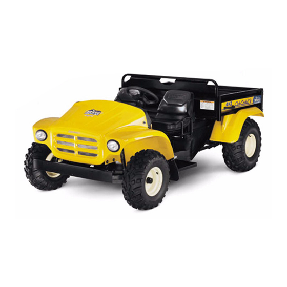
Cub Cadet Big Country 4x2
FORM NO.769-00965
(11/2003)
Advertisement
Table of Contents

Related Manuals for Cub Cadet BIG COUNTRY 4X2


Summary of Contents for Cub Cadet BIG COUNTRY 4X2
- Page 1 Instructions, photographs and illustrations used in this publication are for reference CUB CADET LLC, P.O. BOX 361131, CLEVELAND, OH 44136-0019 use only and may not depict actual model and component parts. © Copyright 2005 MTD Products Inc. All Rights Reserved...
-
Page 3: Table Of Contents
TABLE OF CONTENTS Brakes ....................... 1 Visual Inspection ....................1 Operational Tests....................2 Complete Inspection..................3 Brake Adjustment ....................7 Brake Linkage Adjustment ................9 4x2 Drive – Dana Transaxle................13 Engine/Transmission Cradle ................13 “Dogbone” Link Assembly ................. 13 Transaxle Maintenance .................. -
Page 5: Brakes
Big Country 4 x 2 IMPORTANCE: VISUAL INSPECTION AND OPERATIONAL TEST: It is important that the brakes of the Big Country 4 X 2 1.1. Open the hood of the Big country 4 X 2 and Utility Vehicle be properly maintained in order for the utility vehicle to operate safely and dependably. -
Page 6: Operational Tests
Big Country 4 x 2 1.4. If the operator of the vehicle has any specific 2.7. The parking brake should hold the vehicle brake performance complaints, these complaints securely on a 22 degree incline with an operator should direct the visual examination and be con- and a capacity load (800lbs.) in the bed. -
Page 7: Complete Inspection
Big Country 4 x 2 COMPLETE INSPECTION 3.5. Engage the parking brake. Insure the parking (DRUM AND SHOE REMOVAL) brake assembly is engaging and disengaging properly. The latch (parking brake lever) should 3.1. Perform operational tests if no unsafe conditions hook securely over the tab on the brake pedal have been described by the operator. - Page 8 Big Country 4 x 2 3.9. Inspect the brake cables for any damage or 3.15. Slacken the brake adjuster using a brake wear. Inspect the hardware securing the cables adjuster spoon or flat blade screw driver. to the brake pedal assembly. See Figure 3.15.
- Page 9 Big Country 4 x 2 3.18. Remove the “R” shaped clips securing the brake actuator to the brake shoes. See Figure 3.18. NOTE: If the friction material is contaminated with oil, identify the source, repair the leak, and “R” Shaped clips replace the shoes.
- Page 10 Big Country 4 x 2 3.22. Pry out on the base of the brake shoes while 3.24. Remove the torsion springs. See Figure 3.24. removing the adjuster. See Figure 3.22. Torsion Spring Blue Release from bottom lip extension using a screwdriver spring or brake spoon Brake adjuster...
-
Page 11: Brake Adjustment
Big Country 4 x 2 3.27. Assemble the brakes by reversing the shoe 3.29. Adjust the brakes as described in the “Brake removal process. See Figure 3.27. Adjustment” section of this manual. 3.30. After brake adjustment is complete, perform the Dust cover operational test as described in the “Visual Brake... - Page 12 Big Country 4 x 2 4.4. Disconnect the clevis on the end of each brake 4.7. Set the adjuster so there is slight drag on the cable from the brake actuator extension arm by brake drum when turned by hand. Then adjust removing the cotter pin and clevis pin.
-
Page 13: Brake Linkage Adjustment
Big Country 4 x 2 BRAKE LINKAGE ADJUSTMENT: 4.15. Secure the clevis pins with new cotter pins when adjustment is complete. 4.9. Remove the fasteners that hold the hood closed, and open or remove the hood if it is not already 4.16. - Page 14 Big Country 4 x 2 4.18. There should be 7/8” (.875”) of free-play in the 4.20. When the parking brake is set, the brake switch pedal before the pedal transmits movement to actuator should release the plunger on the brake the cables.
- Page 15 Big Country 4 x 2 4.22. Check to confirm that the parking brake indicator in the instrument panel illuminates when the parking brake is set. If it does not, it may be necessary to adjust the parking brake switch. See Figure 4.22. Parking Brake Switch Parking brake rod Parking brake arm...
- Page 16 Big Country 4 x 2...
-
Page 17: 4X2 Drive - Dana Transaxle
NOTE: The bolt and nut connecting the link to level more frequently until the Big Country 4 X 2 the frame are SAE. The bolt and nut connecting can be taken to an authorized Cub Cadet dealer the cradle to the link are metric. for repair. -
Page 18: Transaxle Removal
SAE30 engine oil or 80W-90 gear lube. This transaxle does not contain bronze gears, so GL4 is a suitable grade if 80W-90 is used. Cub Cadet Hydraulic Drive System Plus (P/N 737-3121) is a suitable premium alterna- tive. 3.9. -
Page 19: 4X2 Pushbutton Gear Selector
4 X 2 Gear Selector DESCRIPTION OF THE GEAR SELECTOR 1.3. The brake switch is tied into the gear selector SYSTEM: circuitry. The vehicle will not shift gears if the brake pedal is not depressed far enough to actu- 1.1. The gear selector on the 4 X 2 Utility Vehicle is ate the switch or if the switch actuator is out of electronically controlled and vacuum actuated. - Page 20 4 X 2 Gear Selector 1.5. The electronic shift module (ESM) processes 1.7. The solenoids are covered by a protective rub- control inputs from the brake switch, neutral sen- ber sheet. To reach them, remove the two wing- sor, and the gear selector buttons on the dash- nuts that secure the plenum to the upper cross- board.
- Page 21 4 X 2 Gear Selector • When the solenoid is de-energized, it provides a 1.10. The vacuum line marked with a blue dot pro- vent to the atmosphere to release the pull on the vides vacuum to the actuator that controls diaphragm.
-
Page 22: Self Diagnostics
4 X 2 Gear Selector 1.13. The forward / reverse actuator is connected to SELF DIAGNOSTICS the shift wedge. Depending on which side of the 2.1. In the event of system malfunction, refer to the actuator vacuum is provided to, the actuator fault code list. -
Page 23: Terms And Definitions
4 X 2 Gear Selector TERMS & DEFINITIONS - Code 2: “FORWARD” and “NEUTRAL” lights flash • ESM - Electronic Shift Module • Action C - Vehicle is in "REVERSE" and opera- tor shifts to "NEUTRAL" • Neutral Switch - in the neutral position the switch is normally closed (NC). -
Page 24: Gear Selector System Diagnostics
4 X 2 Gear Selector GEAR SELECTOR SYSTEM DIAGNOSIS 4.4. Insure that no unsafe conditions will be created by running the vehicle and operating the drive EXPLANATION OF METHODOLOGY: system. See Figure 4.4. • The gear selector system relies on two sub-sys- tems (electrical and vacuum) to work properly. - Page 25 4 X 2 Gear Selector 4.9. If the transmission fails to shift in response to the 4.11. Remove the two wing nuts that secure the hood, control buttons on the dashboard, and the shift and open the hood. wedge can be operated by hand with the engine 4.12.
- Page 26 4 X 2 Gear Selector 4.16. The ESM is visible on the firewall next to the 4.19. Check the operation of the neutral switch. The brake pedal arm. Check the harness connection switch is normally closed. The contact roller to the ESM for tightness, and check the condi- should move freely, breaking continuity when tion of the wires leading to the ESM.
-
Page 27: Vacuum Tests
4 X 2 Gear Selector VACUUM TESTS 5.7. After a visual check for obvious problems, check for the presence of vacuum. NOTE: The vacuum system is robust enough to function reasonably well, even with substantial NOTE: A vacuum gauge that reads from 0 to 30 leaks. - Page 28 4 X 2 Gear Selector 5.9. If a vacuum gauge is connected by T-fitting at 5.10. If a vacuum gauge is connected by T-fitting to the reservoir (accumulator) end of the vacuum the line that leads from the accumulator to line from the intake manifold, the following the solenoid valves, the following readings readings should occur:...
- Page 29 4 X 2 Gear Selector 5.12. Disconnect and plug the fittings that lead to two of the solenoid valves. If the vacuum bleeds NOTE: The vacuum reaction is different from down quickly, the solenoid valve that is still con- one side of the reservoir to the other because nected is at fault.
- Page 30 4 X 2 Gear Selector 5.17. Identify the vacuum line from the reverse sole- noid valve. Use a T-fitting to install the vacuum NOTE: The vacuum line from the forward sole- gauge in-line between the solenoid and the shift noid will have a red dot on the elbow that con- actuator (upper fitting).
-
Page 31: Differential Lock Actuator
4 X 2 Gear Selector 5.19. If vacuum signals vary, check the electrical sig- 5.26. Repeat the test on the vacuum line that con- nal to the vacuum solenoid (see “Gear Selector nects to the reverse side of the vacuum actuator. Electrical System Diagnosis”... -
Page 32: Gear Selector Electrical System
4 X 2 Gear Selector 5.31. The differential lock works independently of the GEAR SELECTOR ELECTRICAL SYSTEM gear selector, and is not controlled by the ESM. DIAGNOSIS. It responds directly to the yellow button to the left 6.1. Any time a computer controlled circuit is being of the steering wheel. - Page 33 4 X 2 Gear Selector 6.3. If the fuse is OK, check the relay. See Figure 6.3. NOTE: Use this basic technique when checking any in-puts or out-puts of the ESM. If power is Key to relay center not found at the device that is connected to the ESM, check for power where the wire in ques- tion reaches the ESM.
- Page 34 4 X 2 Gear Selector 6.6. After power passes through the brake switch, it 6.10. The vacuum tests may identify a vacuum sole- reaches the gear selector button on the dash- noid that is not working properly. Check the board. If power reaches these buttons, the power to the solenoids to confirm whether the brake switch contacts are closed.
-
Page 35: Differential Lock
4 X 2 Gear Selector 6.14. If power is present at the second wire, that 6.17. The red wire with white trace wire will show means that a ground path has successfully been power when the roller on the neutral switch is in created, and the vacuum solenoid should be the detent in the shift wedge. - Page 36 4 X 2 Gear Selector 6.22. The yellow wire from the button activates the dif- 6.26. It will probably be necessary to rotate the input ferential lock solenoid. The green wire from the shaft of the transmission in order to allow the dif- solenoid provides a constant ground.
- Page 37 4 X 2 Gear Selector 6.32. It will probably be necessary to rotate the input shaft of the transmission in order to allow the gears to mesh. This can be done by grasping the driven clutch and rotating it. See Figure 6.32. Figure 6.32 6.33.
- Page 38 4 X 2 Gear Selector...
Need help?
Do you have a question about the BIG COUNTRY 4X2 and is the answer not in the manual?
Questions and answers
What is the top end speed for coconut big country
The top speed of the Cub Cadet BIG COUNTRY 4X2 is 18 mph.
This answer is automatically generated