
Related Manuals for GeoMax Zoom20 Pro Series


Summary of Contents for GeoMax Zoom20 Pro Series
- Page 1 GeoMax Zoom20/30/35 Pro Series User Manual Version 3.0...
- Page 2 Read carefully through the User Manual before you switch on the product. Product identification The type and serial number of your product are indicated on the type plate. Always refer to this information when you contact your agency or GeoMax authorised service workshop. Trademarks •...
-
Page 3: Table Of Contents
Table of Contents In this manual Chapter Page Safety Directions General Definition of Use Limits of Use Responsibilities Hazards of Use Laser Classification 1.6.1 General 1.6.2 Distancer, Measurements with Reflectors 1.6.3 Distancer, Measurements without Reflectors (Reflectorless mode) 1.6.4 Red Laser Pointer 1.6.5 Navigation Light 1.6.6... - Page 4 Check Slope Data Management 12.1 Data Management 12.2 Exporting Data 12.3 Importing Data 12.4 Working with a USB Memory Stick 12.5 Working with Bluetooth 12.6 Working with GeoMax Geo Office and GGO Tools Zoom20/30/35 Pro | 4 Table of Contents...
- Page 5 Calibration 13.1 Overview 13.2 Preparation 13.3 Calibrating Line-of-Sight and Vertical Index Error 13.4 Calibrating the Compensator 13.5 Calibrating the Circular Level of the Instrument and Tribrach 13.6 Inspecting the Laser Plummet of the Instrument 13.7 Servicing the Tripod Care and Transport 14.1 Transport 14.2...
-
Page 6: Safety Directions
Use after misappropriation. • Use of products with obviously recognisable damages or defects. • Use with accessories from other manufacturers without the prior explicit approval of GeoMax. • Aiming directly into the sun. • Inadequate safeguards at the working site. -
Page 7: Limits Of Use
Responsibilities Manufacturer of the GeoMax AG, CH-9443 Widnau, hereinafter referred to as GeoMax, is responsible for supplying the product, product including the user manual and original accessories, in a safe condition. - Page 8 Using the product after incorrect attempts were made to carry out repairs Precautions: Do not open the product. Only GeoMax authorised service workshops are entitled to repair these products. If the product is improperly disposed of, the following can happen: WARNING •...
-
Page 9: Laser Classification
1 2 3 4 5 6 Equip.No.: 1234567 Power: ..V , ...A max. S.No.: GeoMax AG 1 2 3 4 5 6 CH-9443 Widnau Manufactured: 20XX Designed in Switzerland /Made by Hexagon in China Complies with FDA performance standards for laser products except for deviations pursuant to Laser Notice No. -
Page 10: Distancer, Measurements Without Reflectors (Reflectorless Mode)
1 2 3 4 5 6 Equip.No.: 1234567 Power: ..V , ...A max. S.No.: GeoMax AG 1 2 3 4 5 6 CH-9443 Widnau Manufactured: 20XX Designed in Switzerland /Made by Hexagon in China Complies with FDA performance standards for laser products except for deviations pursuant to Laser Notice No. -
Page 11: Red Laser Pointer
1 2 3 4 5 6 Equip.No.: 1234567 Power: ..V , ...A max. S.No.: GeoMax AG 1 2 3 4 5 6 CH-9443 Widnau Manufactured: 20XX Designed in Switzerland /Made by Hexagon in China Complies with FDA performance standards for laser products except for deviations pursuant to Laser Notice No. -
Page 12: Navigation Light
1.6.5 Navigation Light General The integrated Navigation Light produces a visible LED beam from the front side of the telescope. The product described in this section, is excluded from the scope of IEC 60825-1 (2014-05): “Safety of laser products”. The product described in this section, is classified as exempt group in accordance with IEC 62471 (2006-07) and does not pose any hazard provided that the product is used and maintained in accordance with this user manual. -
Page 13: Electromagnetic Compatibility Emc
Electromagnetic radiation can cause disturbances in other equipment. WARNING Although the product meets the strict regulations and standards which are in force in this respect, GeoMax cannot completely exclude the possibility that other equipment may be disturbed. There is a risk that disturbances may be caused in other equipment if the product is used with accessories... - Page 14 Changes or modifications not expressly approved by GeoMax for compliance could void the user's authority WARNING to operate the equipment. Labelling Zoom instru- ment Type: ZOOM XX Pro Art.No.: 1 2 3 4 5 6 Equip.No.: 1234567 Power: ..V , ...A max.
-
Page 15: Description Of The System
Description of the System System Components Main Components a) Instrument b) Computer with GGO or GGO Tools software c) Data transfer Zoom_001 Component Description Instrument An instrument for measuring, calculating and capturing data. Ideally suited for tasks from simple surveys to complex applications. The various lines have a range of accuracy classes and support different features. -
Page 16: Instrument Components
Container contents part 2 of 2 c) Adjustment tools d) USB memory stick e) Plumb bob ZDC220 USB cable* g) Tip for mini prism pole* h) Protective cover ZBA400 battery* Quick Guide k) ZPM100 mini prism* Mini prism pole* Optional 003753_002 Instrument Components Instrument components... -
Page 17: User Interface
User Interface Keyboard Keyboard The keyboard layout may differ depending on the instrument model. a) Alphanumeric keypad b) Navigation key c) ENTER key d) Function keys F1 to F4 e) ESC key FNC key g) PAGE key Zoom_009 Keys Description Page key. -
Page 18: Status Icons
Status Icons Description The icons provide status information related to basic instrument functions. Depending on the display type, different icons are displayed. Icons Icon Description B&W C&T The battery symbol indicates the level of the remaining battery capacity, 75% full shown in the example. For C&T: Tapping the icon opens the SYSTEM INFO screen. -
Page 19: Operating Principles
Description If entry screen: Confirms measured or entered values and continues the process. If message screen: Confirms message and continues with selected action or returns to the previous screen to reselect an option. IR/RL To toggle between IR and RL EDM modes. DISPL. -
Page 20: Pointsearch
Pointsearch Description Pointsearch is a function used by programs to find measured or known points in the memory storage. It is possible to limit the point search to a particular job or to search the whole storage. The search proce- dure always finds known points before measured points that fulfil the same search criteria. -
Page 21: Operation
Operation Instrument Setup Description This topic describes an instrument setup over a marked ground point using the laser plummet. It is always possible to set up the instrument without the need for a marked ground point. Important features • It is always recommended to shield the instrument from direct sunlight and avoid uneven tempera- tures around the instrument. - Page 22 Level up with the elec- The electronic level can be used to precisely level up the instrument using the footscrews of the tribrach. tronic level step-by-step 1) Turn the instrument until it is parallel to two footscrews. 2) Center the circular level approximately by turning the footscrews of the tribrach. 3) Turn on the instrument, and, if tilt correction is set to 1- or 2-axis, the laser plummet will be activated automatically, and the Level Up screen appears.
-
Page 23: Working With The Battery
• For Li-Ion batteries, a single discharging and charging cycle is sufficient. We recommend carrying out the process when the battery capacity indicated on the charger or on a GeoMax product deviates signif- icantly form the actual battery capacity available. -
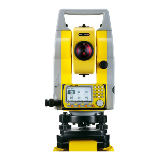
Page 24: Main Menu
Main Menu Description The MAIN MENU is the starting place for accessing all functionality of the instrument. It is usually displayed immediately after the Level & Plummet screen, after switching on the instrument. MAIN MENU Description of the MAIN MENU functions Function Description Apps... -
Page 25: Distance Measurements - Guidelines For Correct Results
Distance Measurements - Guidelines for Correct Results Description A laser distancer (EDM) is incorporated into the instruments. In all versions, the distance can be deter- mined by using a visible red laser beam which emerges coaxially from the telescope objective. There are two EDM modes: •... -
Page 26: Settings
Settings General Settings Access Select Settings from the MAIN MENU. Select General from the Settings menu. Press to scroll through the screens of available settings. GENERAL SETTINGS Field Description Tilt Corr. Tilting compensation deactivated. Vertical angles refer to the plummet line and the horizontal directions are corrected by the standing axis tilt. - Page 27 Field Description Auto-Off Enable The instrument switches off after 20 minutes without any activity, for example no key pressed or vertical and horizontal angle deviation is ±3". Disable Automatic switch-off is deactivated. Battery discharges quicker. Angle Unit Sets the units shown for all angular fields. °...
- Page 28 Field Description Sector Beep Sector Beep sounds at right angles (0°, 90°, 180°, 270° or 0, 100, 200, 300 gon). 1)No beep. 90° 2)Fast beep; from 95.0 to 99.5 gon and 105.0 to 100.5 gon. 3)Permanent beep; from 99.5 to 99.995 gon and from 100.5 to 100.005 gon.
-
Page 29: Edm Settings
Field Description Double PtID Sets if multiple points are able to be recorded with the same point ID in the same job. Allowed Allows multiple points with the same point ID. Not Allowed Does not allow multiple points with the same point ID. Sort Type Time Lists are sorted by time of entry. - Page 30 The refraction correction is taken into account in the calculation of the height differences and the horizontal distance. Refer to "15.7 Scale Correction" for the application of the values entered in this screen. When PPM=0 is selected, the GeoMax standard atmosphere of 1013.25 mbar, 12°C, and 60% relative humidity will be applied. PROJECTION SCALE This screen enables entry of the scale of projection.
-
Page 31: Communication Settings
Communication Settings Description For data transfer the communication parameters of the instrument must be set. Access 1) Select Settings from the MAIN MENU. 2) Select Comm. from the Settings menu. COMMUNICATION SETTINGS BT-PIN To set a code for the Bluetooth connection. ... -
Page 32: Tools
Tools Calibration Description The CALIBRATION menu contains tools to be used for the electronic calibration of the instrument. Using these tools helps to maintain the measuring accuracy of the instrument. Access 1) Select Tools from the MAIN MENU. 2) Select Calib. from the TOOLS menu. 3) Select a calibration option from the CALIBRATION screen. -
Page 33: Loading Software
Page 3 FORMAT Formatting deletes all jobs, formats, codelists and languages. All settings are reset to default. Before selecting FORMAT, to format the internal memory, ensure that all important data is first transferred to a computer. Jobs, formats, codelists, setting files, uploaded languages and firm- ware are deleted by formatting. -
Page 34: Functions
Functions Overview Description Functions can be accessed by pressing FNC from any measurement screen. FNC opens the functions menu and a function can be selected and activated. Functions Function Description Menu Returns to the MAIN MENU. Level Activates the laser plummet and electronic level. Offset Refer to "7.2 Offset". -
Page 35: Column Offset
Offset Default To reset offset values to 0. Column To go to Column Offset. Field Description Trav. Offset Perpendicular offset. Positive if the offset point is to the right of the measured point. Length Off Longitudinal offset. Positive if the offset point is further away than the measured point. Z-Offset Height offset. -
Page 36: Z-Coordinate
Next step Once dH.A. is zero, press ALL to complete the measurement and display the results. COLUMN OFFSET RESULT To record results and return to the main Offset screen. To measure a new cylindrical object. Field Description Defined point ID of the centre point. Easting coordinate of the centre point. -
Page 37: Dist. Offset
Field Description Mode Changes the EDM Mode. Type Changes the prism type. GeoMax Const Displays the prism constant. Pole Length Total length of 2 Dist. Offset pole Dist. P1-P2 Spacing between the centers of the prisms P1 and P2. Meas. Tol Limit for the difference between the given and measured spacing of the prisms. -
Page 38: Edm Continuous
Access 1) Press FNC when within any application. 2) Select Brg/Dist from the FUNCTIONS menu. CONTROL DISTANCE Field Description Difference in bearing between the two points. Grade Difference in gradient between the two points. hDIST Difference in horizontal distance between the two points. sDIST Difference in slope distance between the two points. -
Page 39: Coding
Coding Coding Description Codes contain information about recorded points. With the help of coding, points can be assigned to a particular group simplifying later processing. Codes are stored in codelists, with each codelist supporting a maximum of 200 codes. GSI coding Codes are always stored as free codes (WI41-49), that means that codes are not directly linked to a point. - Page 40 Rapid coding step-by- Press R-Code. step Enter a two-digit number on the keypad. A two-digit code must always be entered on the keypad even if only a one-digit code was assigned. For example: 4 -> enter 04. The code is selected, the measurement triggered and the measured data and code saved. The name of the selected code is displayed after the measurement.
-
Page 41: Mapview Interactive Display Feature
MapView Interactive Display Feature Overview Availability Only available on Zoom30 Pro and Zoom35 Pro. Description MapView is an display feature embedded in the firmware. MapView provides a graphical display of the survey elements which allows for a better overall understanding of how the data being used and measured relates to each other. -
Page 42: Keys, Softkeys And Toolbar
9.3.2 Keys, Softkeys and Toolbar Description Standard functionality is provided by softkeys, keys and a toolbar within MapView. The softkeys are available regardless of the mode in which MapView was accessed and always perform the same functions. Icons are available in a toolbar. The toolbar is always located on the right side of the screen. Some of the functions performed by the icons can also be replicated using a softkey or key in the same mode as when the icon appears. -
Page 43: Applications - Getting Started
Applications - Getting Started 10.1 Overview Description Applications are predefined programs, that cover a wide spectrum of surveying duties and facilitate daily work in the field. The following applications are available, although application packages for each instru- ment may vary from that stated below: •... -
Page 44: Selecting The Station
Field Description Name of an existing job to be used. User Name of user, if entered. Date Date the selected job was created. Time Time the selected job was created. Next step • Either, press OK to continue with the selected job. •... -
Page 45: Orientation With Coordinates
MANUAL ANGLE SETTING HA=0 To set Brg: 0 Field Description Horizontal direction of the station. TgtHGT. Height of the reflector. BS ID Point ID of the backsight point. Next step • Either, press ALL to measure and record the distance and horizontal angles. This will calculate and set the orientation and return to the Pre-Settings screen. - Page 46 Stn. Orientation result Field Description Number of points used in the calculation. Station name for which the orientation has been set. HA Corr Horizontal correction Std.Dev Standard deviation indicating the potential variance between the true orientation and that calculated. Next step •...
-
Page 47: Applications
Applications 11.1 Common Fields Description of fields The following table describes common fields that are found within the firmware applications. These fields are described here once and not repeated in the application chapters unless the field has a specific meaning within that application. Field Description Pt, Pt 1... -
Page 48: Set Out
11.3 Set Out Description Set Out is an application used to place marks in the field at predetermined points. These predetermined points are the points to be staked. The points to be staked may already exist in a job on the instrument, or be manually entered. -
Page 49: Resection
Field Description dLength Longitudinal offset: Positive if set out point is further away than the measured point. dTrav. Perpendicular offset: Positive if set out point is to the right of the measured point. Easting offset: Positive if set out point is to the right of the measured point. Northing offset: Positive if set out point is further away than the measured point Height offset: Positive if set out point is higher than the measured point. -
Page 50: Measuring Information
11.4.2 Measuring Information Measurement The following measurement sequences are possible: sequences • Horizontal direction and vertical-angles only (resection) • Distance and horizontal direction and vertical-angle • Horizontal direction and vertical-angles to some point(s) and horizontal direction and vertical angles plus distance to other point(s). Single face I, single face II, or dual face I and II measurements are always possible. -
Page 51: Missing Line Measurement
Messages The following are important messages or warnings that may appear. Messages Description Selected point has no valid This message occurs if the selected target point has no Easting or data! Northing coordinate. Max 5 points supported! 5 points have already been measured and another point is selected. The system supports a maximum of 5 points. -
Page 52: Cogo
MISSING LINE RESULT - NewPt 1 Polygonal method To calculate an additional line. Application starts again at point 1. NewPt 2 To set point 2 as the starting point of a new line. A new point 2 must be measured. RADIAL To switch to radial method. -
Page 53: Intersections
Traverse Use the traverse subapplication to calculate the position of a new point using the bearing and the distance from a known point. Offset optional. Known Known point Direction from P1 to P2 Distance between P1 and P2 Positive offset to the right Negative offset to the left Unknown COGO point without offset... -
Page 54: Offsets
By Points Use the line-line subapplication to calculate the intersection point of two lines. A line is defined by two points. To add a shift to the lines do the following: 1) Select Page 2 (Colour & Touch display) or Page 2/2 (Black & White display) from the INTERSEC- TION 4 POINTS screen. -
Page 55: Extension
11.6.5 Extension Access Select Line-Ex from the COGO menu. Extension Use the Extension subapplication to calculate the extended point from a known base line. Known Baseline start point d L1 Baseline end point dL1,dL2 Distance d L2 Unknown P2, P4 Extended COGO points 11.7 Area &... -
Page 56: Remote Elevation
Graphical representa- P0 Instrument station tion P1 Target point which defines the sloped reference plane P2 Target point which defines the sloped reference plane P3 Target point which defines the sloped reference plane P4 Target point Constant height Perimeter (3D), polygonal length from the start point to the current measured point of the area (3D) Area (3D), projected onto the sloped reference... -
Page 57: Reference Element - Reference Line
REMOTE ELEVATION - Aim the instrument at the inaccessible remote point. Aim at remote point Field Description hDIST Height difference between the base point and the remote point. d.d.Z Calculated difference in Height between the base point and the remote point. Height of the remote point. -
Page 58: Defining The Reference Line
11.9.3 Defining the Reference Line Description The base line can be offset from, either longitudinally, in parallel or vertically, or be rotated around the first base point. This new line created from the offsets is called the reference line. All measured data refers to the reference line. -
Page 59: Subapplication Measure Line & Offset
11.9.4 Subapplication Measure Line & Offset Description The Measure Line & Offset subapplication calculates from measurements or coordinates, longitudinal offsets, parallel offsets and height differences of the target point relative to the reference line. Reference line 1RP Start point Measured point Longitudinal offset dOff Parallel offset Example of height... -
Page 60: Grid Setout
Next step Press OK to proceed to measurement mode. SET OUT The signs for the distance and angle differences are correction values (required minus actual). The arrows indicate the direction to move to get to the set out point. NextPt To add the next point to be set out. - Page 61 Grid definition Enter the chainage and the increment of grid points in length and cross direction of the reference line. Field Description Start Chain Distance from the reference line start point to the beginning grid start point. Increment Length of incrementation. Offset Offset distance from the reference line.
-
Page 62: Line Segment
11.9.7 Line Segment Description The line segment application calculates and displays the setout elements for the points along the line, orthogonal (dL, dO, dH) and polar (dH.A., dH.D., d.d.z.). Line Segment is limited to the reference line, between the defined start and end points of the line. Example Line Segment Setout Instrument station First reference point... -
Page 63: Reference Element - Reference Arc
LINE SEGMENT - The signs for the distance and angle differences are correction values (required minus actual). The arrows SETOUT indicate the direction to move to get to the setout point. Field Description Segm Segment number. Includes the misclosure segment, if applicable. CumL Cumulation of the segment lengths. -
Page 64: Defining The Reference Arc
11.10.2 Defining the Reference Arc Description The reference arc can be defined by a center point and start point, or a start point, end point, and radius. All points can be either measured, manually entered, or selected from the memory. Off - Start point End point... -
Page 65: Subapplication Setout
11.10.4 Subapplication Setout Description The setout subapplication calculates the difference between a measured point and the calculated point. The reference arc application supports four ways to set out: • Set out point • Set out chord • Set out arc •... -
Page 66: Construction
Field Description Angle For set out angle: The angle around the center point of the arc, of the points to be set out. Line For set out arc, chord and angle: Longitudinal offset from the reference arc. This is calcu- lated by the arc length, chord length or angle and the selected misclosure distribution. -
Page 67: Layout
11.11.2 Layout Description Search or enter points for setting out relative to the defined construction line. The on-screen graphics show the position of the prism relative to the set out point. Below the graphic, the exact values are displayed, combined with arrows to show the direction for setting out the point. ... -
Page 68: Road 2D
11.12 Road 2D Description Road Alignment is an application used to measure or set out points relative to a defined element. The element can be a line, curve or spiral. Chainage, incremental set outs and offsets (left and right) are supported. -
Page 69: Road 3D
For a spiral element: • Select the method to be used, Rad/Par or Rad/Len. • Enter the radius and parameter, or radius and length, depending on the method chosen. • Select the type and direction of the spiral. • Press OK. Spiral type Spiral in Sprial out... -
Page 70: Basic Terms
11.13.2 Basic Terms Elements of a road Road projects consist, in general, of a horizontal and a vertical alignment. project Any project point P1 has E, N and Z coordinates in a deter- mined coordinate system and has three positions. Position on natural surface a b c P1"... - Page 71 Element Description Spiral types • Entry spiral (Spiral in = A): Spiral with a radius of infinity at the start and a given radius at the end. • Exit spiral (Spiral out = B): Spiral with a given radius at the start and radius of infinity at the end.
- Page 72 Horizontal and vertical geometry elements combined TSOX_116 a = Horizontal alignment (top view) b = Vertical alignment (front view) Radius 1 Straight Radius 2 Curve Straight Straight Curve with R1 Parabola Partial spiral with R1 and R2 Straight Curve with R2 Spiral out with R2 and R= ∞...
-
Page 73: Creating Or Uploading Alignment Files
11.13.3 Creating or Uploading Alignment Files Select Apps from the MAIN MENU. Access Select ROAD 3D from the Apps menu. Complete program pre-settings. Select Alignment File: Field Description Horiz. Aln. List of available horizontal alignment files. Using a horizontal alignment file is mandatory. Verti. -
Page 74: Setout
11.13.4 Setout Description The application Setout is used to stake out points relative to an existing alignment. The height difference is relative to a vertical alignment or manually entered height. Instrument station Target point Measured point Measured point Horizontal alignment Defined chainage Offset Height difference... -
Page 75: Check
11.13.5 Check Description The application Check is used for as-built checks. The points can be measured or selected from the memory. The chainage and offset values are relative to an existing horizontal alignment, and the height difference is relative to a vertical alignment or manually entered height. Instrument station Target point Target point... -
Page 76: Slope Setout
11.13.6 Slope Setout Description The application Slope Setout is used to stake out the catch point, which is the intersection point of a defined slope with the natural surface. The slope is always defined as starting from a hinge point. If the parameter offset right/left and height difference are not entered, the point at the defined chainage on the horizontal alignment is the hinge point. - Page 77 Slope Setout Field Description DefChain Defined chainage for stake out. dChain Difference between the defined chainage and the measured chainage. dOffset Horizontal offset between the catch point of defined slope and the measured position. Vertical offset between the catch point of the defined slope and the measured position. A cut is above the slope, a fill is below the slope.
-
Page 78: Check Slope
11.13.7 Check Slope Description The application Check Slope is used for as-built checks and to get information about slopes, for example on a natural surface. If the parameter offset left/right and height difference are not entered, the point on the horizontal alignment is the hinge point. Measured point Horizontal alignment Defined offset... -
Page 79: Data Management
Data Management 12.1 Data Management Access Select Data from the MAIN MENU. DATA MANAGEMENT The Data Management menu contains all functions for entering, editing, checking and deleting data in the field. 1 - 7 To select menu item. Menu item Description To view, create and delete jobs. -
Page 80: Importing Data
DATA EXPORT SEARCH To search for jobs within the internal memory. DISPL. To list all jobs within the internal memory. Field Description USB memory stick or RS232 serial interface. Data Type Data type to be transferred to Interface: Observations, KnownPts or Observ. &KnownPts. Data type to be transferred to USB-Stick: Observations, KnownPts, Observ. -
Page 81: Working With A Usb Memory Stick
Zoom_008 Always return to the Main Menu before removing the USB memory stick. GeoMax cannot be held responsible for data loss or any other error that may occur when using a USB memory stick. • Keep the USB memory stick dry. -
Page 82: Working With Bluetooth
The Zoom30 Pro/Zoom35 Pro Bluetooth does not establish or manage the data transfer. 12.6 Working with GeoMax Geo Office and GGO Tools Description The program package GGO is used for the data exchange between the instrument and a computer. It contains several auxiliary programs in order to support the instrument. -
Page 83: Calibration
Overview Description GeoMax instruments are manufactured, assembled and adjusted to a high quality. Quick temperature changes, shock or stress can cause deviations and decrease the instrument accuracy. It is therefore recommended to calibrate the instrument from time to time. This can be done in the field by running through specific measurement procedures. -
Page 84: Calibrating Line-Of-Sight And Vertical Index Error
13.3 Calibrating Line-of-Sight and Vertical Index Error Line-of-sight error The line-of-sight error, or horizontal collimation error is the deviation from the perpendicular between the tilting axis and the line of sight. The effect of the line-of-sight error to the horizontal direction increases with the vertical angle. -
Page 85: Calibrating The Compensator
Messages The following are important messages or warnings that may appear. Messages Description VA-angle not suitable for The vertical angle deviates from the required horizontal / line-of-sight, or adjustment ! in face II the vertical angle deviates by more than 5° from the target point. Aim at the target point with an accuracy of min. -
Page 86: Calibrating The Circular Level Of The Instrument And Tribrach
If the center of the laser dot makes a clearly circular movement, or moves more than 3 mm away from the point which was first marked, an adjustment may be required. Call your nearest GeoMax service centre. Depending on brightness and surface type, the size of the laser dot can vary. At a height of 1.5 m an average diameter of 2.5 mm is estimated. -
Page 87: Servicing The Tripod
13.7 Servicing the Tripod Service the tripod step- by-step The connections between metal and timber components must always be firm and tight. 1) Tighten the leg cap screws moderately with the allen key supplied. 2) Tighten the articulated joints on the tripod head just enough to keep the tripod legs open when lifting the tripod off the ground. -
Page 88: Care And Transport
Shipping When transporting the product by rail, air or sea, always use the complete original GeoMax packaging, transport container and cardboard box, or its equivalent, to protect against shock and vibration. - Page 89 Damp products Dry the product, the transport container, the foam inserts and the accessories at a temperature not greater than 40°C /104°F and clean them. Remove the battery cover and dry the battery compartment. Do not repack until everything is completely dry. Always close the transport container when using in the field.
-
Page 90: Technical Data
Technical Data 15.1 Angle Measurement Accuracy Available Standard deviation HA, Display resolution angular accura- VA, ISO 17123-3 cies ["] [mgon] ["] [°] [mgon] [mil] 0.0001 0.01 0.0001 0.01 0.0001 0.01 0.0001 0.01 0.0001 0.01 Characteristics Absolute, continuous, diametric. Updates each 0.1 to 0.3 s. 15.2 Distance Measurement with Reflectors Range... -
Page 91: Distancer, Measurements Without Reflectors (Reflectorless Mode)
15.3 Distancer, Measurements without Reflectors (Reflectorless mode) Range A2 (without reflector) Kodak Gray Card Range D Range E Range F [ft] [ft] [ft] White side, 90 % reflective 250 820 Grey side, 18 % reflective 110 360 A4 (without reflector) Kodak Gray Card Range D Range E... -
Page 92: Distance Measurement Reflector (Long Range)
IATA Dangerous Goods Regulations. GeoMax has developed Guidelines on “How to carry GeoMax products” and “How to ship GeoMax products” with Lithium batteries. Before any transportation of a GeoMax product, we ask you to consult these guidelines on our web page (www.geomax-positioning.com/dgr) to ensure that you... -
Page 93: Zoom30 Pro/Zoom35 Pro
FCC Part 15 (applicable in US). Conformity to national • Hereby, GeoMax AG, declares that the Zoom30 Pro/Zoom35 Pro instrument is in compliance with the regulations essential requirements and other relevant provisions of Directive 1999/5/EC and other applicable European Directives. The declaration of conformity is available from GeoMax AG. - Page 94 Instrument Dimensions 86.6 mm 86.6 mm 226 mm 173.2 mm Zoom_024 Zoom_023 Weight Instrument: 4.2 kg - 4.5 kg (depending on hardware configuration) Tribrach: 760 g Battery ZBA400: 110 g Without tribrach: 196 mm Tilting axis height With tribrach: 240 mm ±5 mm Recording Model Memory Type...
-
Page 95: Scale Correction
Humidity Type Protection Zoom instrument Max 95% non condensing. The effects of condensation are to be effectively counteracted by periodically drying out the instrument. Navigation Light Available for Zoom30 Pro. Working range: 5 m to 150 m (15 ft to 500 ft) Position accuracy: 5 cm at 100 m (1.97"... -
Page 96: Reduction Formulas
Atmospheric correction Atmospheric corrections in ppm with temperature [°F], air pressure [inch Hg] and height [ft] at 60 % rela- °F tive humidity. 16 17 18 19 20 21 22 23 24 25 26 27 28 29 30 31 32 inch Hg 130°F 130°F 120°F... -
Page 97: Software Licence Agreement
GeoMax. Such software is protected by copyright and other laws and its use is defined and regulated by the GeoMax Software Licence Agreement, which covers aspects such as, but not limited to, Scope of the Licence, Warranty, Intellectual Property Rights, Limitation of Liability, Exclusion of other Assurances, Governing Law and Place of Jurisdiction. -
Page 98: Glossary
Glossary Instrument axis ZA = Line of sight / collimation axis Telescope axis = line from the cross hairs to the center of the objective. SA = Standing axis Vertical rotation axis of the telescope. KA = Tilting axis Horizontal rotation axis of the telescope. Also known as the Trunion axis. - Page 99 Explanation of displayed Indicated meteorological corrected slope distance E, N, Z data between instrument tilting axis and center of prism/laser Indicated meteorological corrected horizontal distance Height difference between station and target point Reflector height above ground Instrument height above ground Stn.E, Stn.N, Stn.Z Easting, Northing and Height coordinates of station E, N, Z...
-
Page 100: Appendix A Menu Tree
Output, GSI Format, Mask, Code Saving, Language, Language Choise, Touch Screen, Double PtID, Sort Type, Sort Order, Pre-/Suffix, Identi- fier. |—— EDM |—— EDM Mode, Prism Type, GeoMax Const., Abs. Const., Laser-Beam, NavLight |—— Comm. |—— Port, Bluetooth, Baud Rate, Data Bits, Parity, Endmark, Stop bits, Acknowledge |——... -
Page 101: Appendix B Directory Structure
Appendix B Directory Structure Description On the USB memory stick, files are stored in certain directories. The following diagram is the default direc- tory structure. |—— CODES • Codelists (*.cls) Directory Structure |—— FORMATS • Format files (*.frt) |—— JOBS •... -
Page 102: Appendix C Connector Pin Layout
Appendix C Connector PIN Layout Connector PIN layout 009175_001 Pin number Name Function Direction Signal Ground PWR_IN/ USB_V Bus Power-In, 10..15V (typical 12V) / USB 5V TH_Tx RS232, Transmit TH_Rx RS232, Receive D_Minus USB, Signal Low D_Plus USB, Signal High Zoom20/30/35 Pro | 102 Connector PIN Layout... - Page 104 GeoMax Zoom20/30/35 Pro Series 780085-3.0.0en Original text © 2015 GeoMax AG, Widnau, Switzerland GeoMax AG www.geomax-positioning.com...
Need help?
Do you have a question about the Zoom20 Pro Series and is the answer not in the manual?
Questions and answers