Table of Contents
Advertisement
Quick Links
Advertisement
Chapters
Table of Contents

Subscribe to Our Youtube Channel
Related Manuals for GeoMax Zeta125


Summary of Contents for GeoMax Zeta125
- Page 1 GeoMax Zeta125/Zeta125s User Manual Version 1.1...
- Page 3 GeoMax Zeta125/Zeta125s User Manual Version 1.1 English...
- Page 4 Zeta125/ Zeta125s | 2 Introduction Introduction About the instru- The Zeta125 pipe laser is built to withstand the harsh environment of the ment construction site. The integrated Li-Ion battery with internal charge control provides a long oper- ating time. The battery can be recharged while the instrument is working.
- Page 5 All instructions required in order to safely operate and handle the product throughout its life cycle can be found here. Read and follow the User Manual before using the product. Keep all documentation for future reference! Zeta125/ Zeta125s | 3 Introduction...
- Page 6 Zeta125/ Zeta125s | 4 Table of Contents Table of Contents In this manual Chapter Page Safety Directions 1.1 General 1.2 Definition of Use 1.3 Limits of Use 1.4 Responsibilities 1.5 Hazards of Use 1.6 Laser Classification 1.6.1 Laser Class 2 1.6.2...
- Page 7 5.3.2 Auto Alignment Procedure 5.4 Troubleshooting Care and Transport 6.1 Maintenance 6.2 Transport 6.3 Storage 6.4 Cleaning and Drying Technical Data 7.1 Technical Data 7.2 Conformity to National Regulations 7.3 Dangerous Goods Regulations Zeta125/ Zeta125s | 5 Table of Contents...
- Page 8 Zeta125/ Zeta125s | 6 Safety Directions 1 Safety Directions 1.1 General Description The following directions enable the person responsible for the product, and the person who actually uses the equipment, to anticipate and avoid operational hazards. The person responsible for the product must ensure that all users understand these directions and adhere to them.
- Page 9 Important paragraphs which must be adhered to in prac- tice as they enable the product to be used in a technically correct and efficient manner. Zeta125/ Zeta125s | 7 Safety Directions...
- Page 10 Zeta125/ Zeta125s | 8 Safety Directions 1.2 Definition of Use Intended use • Remote control of product. • The instrument projects a collimated beam of laser light for the purposes of alignment of gravity flow pipelines. • The laser beam can be detected by viewing it on an opaque red target.
- Page 11 The following advice is only valid for battery charger, power adapter and car adapter. Environment Suitable for use in dry environments only and not under adverse conditions. Zeta125/ Zeta125s | 9 Safety Directions...
- Page 12 Zeta125/ Zeta125s | 10 Safety Directions 1.4 Responsibilities Manufacturer of GeoMax AG, CH-9443 Widnau, hereinafter referred to as GeoMax, is respon- the product sible for supplying the product, including the user manual and original acces- sories, in a safe condition.
- Page 13 Precautions: When setting up the product, make sure that the accessories are correctly adapted, fitted, secured, and locked in position. Avoid subjecting the product to mechanical stress. Zeta125/ Zeta125s | 11 Safety Directions...
- Page 14 Zeta125/ Zeta125s | 12 Safety Directions During the transport, shipping or disposal of batteries it is possible for inap- CAUTION propriate mechanical influences to constitute a fire hazard. Precautions: Before shipping the product or disposing of it, discharge the batteries by running the product until they are flat.
- Page 15 Using the product after incorrect attempts were made to carry out repairs Precautions: Do not open the product. Only GeoMax authorised service centres are entitled to repair these products. If the product is improperly disposed of, the following can happen: WARNING •...
- Page 16 Zeta125/ Zeta125s | 14 Safety Directions Precautions: The product must not be disposed with household waste. Dispose of the product appropriately in accordance with the national regulations in force in your country. Always prevent access to the product by unauthorised personnel.
- Page 17 IEC 60825-1 (2014-05) and IEC TR 60825-14 (2004-02). Potential hazards are not only related to direct beams but also to reflected CAUTION beams aimed at reflecting surfaces such as prisms, windows, mirrors, metallic surfaces, etc. Zeta125/ Zeta125s | 15 Safety Directions...
- Page 18 Zeta125/ Zeta125s | 16 Safety Directions Precautions: 1) Do not aim at areas that are essentially reflective, such as a mirror, or which could emit unwanted reflections. 2) Do not look through or beside the optical sight at prisms or reflecting objects when the laser is switched on, in laser pointer or distance meas- urement mode.
- Page 19 This device complies with part 15 of the FCC Rules. Operation is subject to the following two conditions: (1) This device may not cause harmful interference, and (2) This device must accept any interference received, including interference that may cause undesired operation. 014508_001 Zeta125/ Zeta125s | 17 Safety Directions...
- Page 20 Zeta125/ Zeta125s | 18 Safety Directions 1.6.2 Laser Class 3R Laser class 3R The laser source built into the product produces a visible laser beam which emerges from the laser aperture. The laser product described in this section is classified as laser class 3R in accordance with: •...
- Page 21 This device complies with part 15 of the FCC Rules. Operation is subject to the following two conditions: (1) This device may not cause harmful interference, and (2) This device must accept any interference received, including interference that may cause undesired operation. 015003_001 Zeta125/ Zeta125s | 19 Safety Directions...
- Page 22 Zeta125/ Zeta125s | 20 Safety Directions Labelling Zeta125s Type: Zeta125s Manufactured for GeoMax AG Art.No.: 829480 CH-9443 Widnau Power: 10.8V / 2.7A Made in the USA S.No.: acc. to IEC 60825-1:2014 / λ = 635nm, P = 4.75 mW cw Complies with FDA performance standards for laser products except for deviations pursuant to Laser Notice Nr.
- Page 23 This device complies with part 15 of the FCC Rules. Operation is subject to the following two conditions: (1) This device may not cause harmful interference, and (2) this device must accept any interference received, including interference that may cause undesired operation. 007210_002 Zeta125/ Zeta125s | 21 Safety Directions...
- Page 24 WARNING Although the product meets the strict regulations and standards which are in force in this respect, GeoMax cannot completely exclude the possibility that other equipment may be disturbed. There is a risk that disturbances may be caused in other equipment if the...
- Page 25 Although the product meets the strict regulations and standards which are in force in this respect, GeoMax cannot completely exclude the possibility that the product may be disturbed by intense electromagnetic radiation, for example, near radio transmitters, two-way radios or diesel generators.
- Page 26 Connect the equipment into an outlet on a circuit different from that to which the receiver is connected. • Consult the dealer or an experienced radio/TV technician for help. Changes or modifications not expressly approved by GeoMax for compliance WARNING could void the user's authority to operate the equipment.
- Page 27 Charger e) Leg depot Manual g) Target plate insert for universal target h) Spare battery Clip-in target plate for 125 mm pipes Remote control k) Universal compartment: Manuals, spare cables, target plate etc. 008385_001 Zeta125/ Zeta125s | 25 Container Contents...
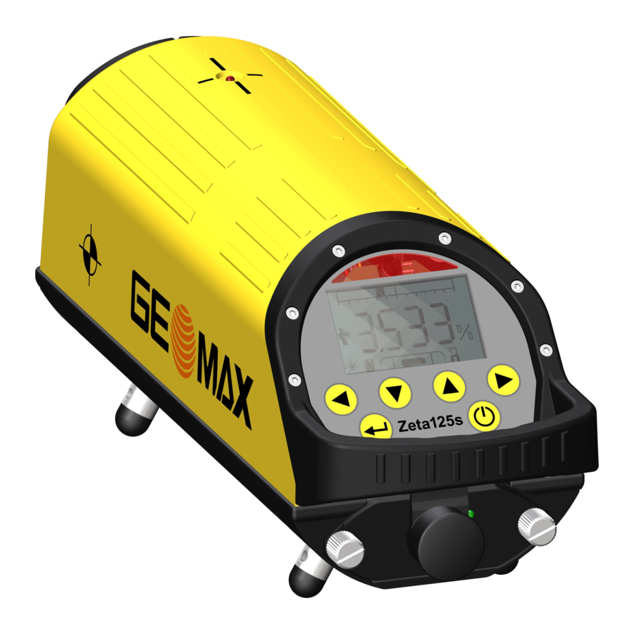
- Page 28 Zeta125/ Zeta125s | 26 Product Overview 3 Product Overview Instrument components a) Laser aperture b) Pivot LED c) 5/8“ thread d) Metal feet e) Display Keypad g) Handle h) Battery Charge socket 008386_001...
- Page 29 Keypad Description Left arrow key Down arrow key Up arrow key Right arrow key Enter key ON/OFF key Zeta125/ Zeta125s | 27 Product Overview...
- Page 30 +10 °C to +20 °C/+50 °F to +68 °F if possible. • It is normal for the battery to become warm during charging. Using the chargers recommended by GeoMax, it is not possible to charge the battery once the temperature is too high. •...
- Page 31 Pull the screws tight. Otherwise water can come into the battery case and can damage the battery. To turn on the Zeta125 after long time storage without battery pack: Reinsert the battery pack and press the ON/OFF key for approx- imately 3 seconds.
- Page 32 Zeta125/ Zeta125s | 30 Product Overview Insert and remove the battery of the remote control 008394_001 Step Description If the LED on the remote control is flashing red while sending, the batteries are low. Loosen the six screws on the back case of the remote control to open the battery housing.
- Page 33 • the correct position of the back case. • that the back case is free from dirt. Close the housing and tighten the six screws to make sure that the remote control is waterproof. Zeta125/ Zeta125s | 31 Product Overview...
- Page 34 Step Description Connect the charger to an AC outlet. Remove the protection cap onto the charge socket of the Zeta125. Attach the plug to the charge socket of the Zeta125. Plug the power cord into an external power supply. Charging starts.
- Page 35 008396_001 A flashing laser beam symbol indicates the active self levelling. When the symbol is lit, the laser is levelled and the laser beam is continu- ously on. Zeta125/ Zeta125s | 33 Product Overview...
- Page 36 Zeta125/ Zeta125s | 34 Product Overview Display a) Line control laser position b) Laser beam status c) Battery status d) Laser beam grade e) Key lock status Electronic vial 007153_001 Entering a grade Refer to "4 Menu" for instructions how to set the entry format to percent.
- Page 37 Adjust the target plate to the pipe diameter. Move the target plate in the base until the mark is on the line of the feet length mounted at the laser. Tighten the target plate in place. Zeta125/ Zeta125s | 35 Product Overview...
- Page 38 Zeta125/ Zeta125s | 36 Product Overview 150 mm diameter: 008398_001 200 mm diameter: 008399_001 250 mm diameter: 008400_001...
- Page 39 Adjust the line direction using the remote control. Refer to "Keys". Move the pipe to the correct height and direction. When the beam is in the target sign the pipe is in the desired slope. Zeta125/ Zeta125s | 37 Product Overview...
- Page 40 Zeta125/ Zeta125s | 38 Product Overview Press the corresponding arrow key on Aligning the laser the laser or on the remote control. line to the target The beam movement starts slowly and increases in speed while an arrow key is pressed.
- Page 41 Air turbulence in the pipe cause refraction. The effect occurs particularly, when a wet or cold pipe is heated up quickly through the sunlight. The rising air deflects the laser beam and causes a flicker. Zeta125/ Zeta125s | 39 Product Overview...
- Page 42 Zeta125/ Zeta125s | 40 Product Overview Ventilate the pipe or place laser and target temporarily on top of the pipe. When the pipe is dry or heated up to the ambient level, the laser spot is stable again. Resetting...
- Page 43 Error 0 Data Error 1) Turn laser off and on again. The instrument 2) Check calibration. turns off auto- 3) If the message appears again, matically. contact your service centre. Zeta125/ Zeta125s | 41 Product Overview...
- Page 44 Key lock function b) Auto alignment function c) Line control adjustment (up move- ment in calibration mode) d) Left arrow key e) Sleep mode (down movement in calibration mode) g) Key for Pivot LED (on the Zeta125) h) Right arrow key 008404_001...
- Page 45 All keys on the remote control and on the laser are locked. Locked keys avoid unintentional change when the laser is in use. To deactivate the function press the lock key again. Zeta125/ Zeta125s | 43 Product Overview...
- Page 46 These keys can stop the upward movement of the beam, if the height of the measuring rod is reached earlier. Zeta125: Press the key to turn on the second laser scan beam. The beam position can now be aligned manually or with the right/left arrow keys.
- Page 47 >INFO simultaneously until the SET UP screen SETTINGS appears. CALIBRATION SERVICE The active menu step is highlighted and > is EXIT displayed in front of the line. 007179_001 Press to open the menu option. Zeta125/ Zeta125s | 45 Menu...
- Page 48 Zeta125/ Zeta125s | 46 Menu INFO menu This screen shows: • the software version, • the working hours of the instrument and • internal adjustment values for authorised service centres. All fields are display only fields. Next step Press to return to the SET UP menu.
- Page 49 If you feel unsure about doing the calibration, contact your authorised dealer or GeoMax. Test to see if a horizontal calibration is required Step Description Define a horizontal 60 m distance between a reference point and target point. Zeta125/ Zeta125s | 47 Menu...
- Page 50 Zeta125/ Zeta125s | 48 Menu Step Description Defining a horizontal distance using an optical level: In a distance of 30 m from the level, define a reference point by a yardstick. Turn the level by 180 degrees. Define a target point in a distance of 30 m from the level.
- Page 51 Wait until SET is displayed. Repeat step 3. and 4. if necessary. • To save the position: Press the lock symbol on the remote control. • To leave the calibration mode without storing the change: Turn off the laser. Zeta125/ Zeta125s | 49 Menu...
- Page 52 Zeta125/ Zeta125s | 50 Menu SERVICE menu The SERVICE menu is PIN protected. The menu is only accessible by authorised service centres. Next step Step Description Move the cursor to EXIT. Press the Enter key to return to the SET UP menu.
- Page 53 The unit is unsuitable for different application and does not function as intended with non-approved modifications or accessories. Opening the instrument (except exchanging the battery) or making any other modifications does adversely affect the intended function. Zeta125/ Zeta125s | 51 Auto Target...
- Page 54 Zeta125/ Zeta125s | 52 Auto Target 5.1 Product Overview Instrument components a) Secure Knob for pipe target b) Pipe target c) Keypad d) Secure Knobs for battery compartment e) Level vial Rubber feet g) Screws for pipe target holder h) 1/4“ thread...
- Page 55 ON/OFF key e) Auto alignment LED (green) Auto alignment key g) Right LED (red) h) Right arrow key 008412_001 Functions of the Description keys When facing the laser: Moves the laser beam to the left. Zeta125/ Zeta125s | 53 Auto Target...
- Page 56 Zeta125/ Zeta125s | 54 Auto Target Description Switches the auto target on or off. Starts the auto alignment function. When facing the laser: Moves the laser beam to the right. Switches between narrow mode and wide mode. Starts the detector mode.
- Page 57 Flashing Auto alignment is running and seeking the auto target in wide mode. 008423_001 Right and left (red): Solid Auto target is in wide mode. 008424_001 Flashing Auto target has timed out. 008425_001 Left (red) and ON/OFF LED (green): Zeta125/ Zeta125s | 55 Auto Target...
- Page 58 Zeta125/ Zeta125s | 56 Auto Target Description Solid In laser receiver mode: The rotating laser beam is to the left of the centre. 008426_001 Right (red) and ON/OFF (green): Solid In laser receiver mode: The rotating laser beam is to the right of the centre.
- Page 59 The auto target is powered by 4 AA Alkaline batteries. remove the batteries 008432_001 Step Description Remove the two screws from the battery compartment with a coin for example. The screws are captive at the battery pack to avoid losing them. Zeta125/ Zeta125s | 57 Auto Target...
- Page 60 Zeta125/ Zeta125s | 58 Auto Target Step Description Remove or change the batteries. Close the battery compartment and pull the screws tight.
- Page 61 The narrow mode is faster than the wide mode. Align the auto target with +/-3° to the centre of the auto target. Switching Step Description between narrow Press the ON/OFF key to power down the auto target. mode and wide mode Zeta125/ Zeta125s | 59 Auto Target...
- Page 62 Zeta125/ Zeta125s | 60 Auto Target Step Description With the auto target powered down, press and hold the Auto alignment key and at the same time turn on the auto target. Release both, the ON/Off key and the Auto alignment key at the same time.
- Page 63 Zeta125s and the auto target. While the auto alignment is running, nobody must move through the area. Step 3 To start the auto alignment procedure, press the auto alignment key Zeta125/ Zeta125s | 61 Auto Target...
- Page 64 Zeta125/ Zeta125s | 62 Auto Target The green auto alignment LED is flashing and the main beam of the Zeta125s switches off. Facing the Zeta125s from the auto target, the Zeta125s pivots to the right. The vertical rotating beam switches on and the auto alignment procedure begins.
- Page 65 There was not permanently free sight between Zeta125s and the auto target, for example a person moves through the beam during the auto alignment procedure. b) The alignment of the Zeta125s was not in the +/-3° or +/-6° area of the auto alignment modes. Zeta125/ Zeta125s | 63 Auto Target...
- Page 66 Zeta125/ Zeta125s | 64 Auto Target If the Alignment of the Zeta125s was not in +/-3° or +/-6° area, precede as follows: Step Description If the narrow mode is activated: Switch to the wide mode. If the wide mode is activated: Set up the laser again.
- Page 67 A calibration interval of one year is recommended. Check the instrument before use. The manufacturer and its representatives are not responsible for any damages resulting from using a maladjusted instru- ment. Zeta125/ Zeta125s | 65 Care and Transport...
- Page 68 Shipping When transporting the product by rail, air or sea, always use the complete original GeoMax packaging, container and cardboard box, or its equivalent, to protect against shock and vibration. Field adjustment Periodically carry out test measurements and perform the field adjustments indicated in the User Manual, particularly after the product has been dropped, stored for long periods or transported.
- Page 69 6.3 Storage Product Respect the temperature limits when storing the equipment, particularly in summer if the equipment is inside a vehicle. Refer to "7 Technical Data" for information about temperature limits. Zeta125/ Zeta125s | 67 Care and Transport...
- Page 70 Zeta125/ Zeta125s | 68 Care and Transport 6.4 Cleaning and Drying Basic Cleaning Basic cleaning is recommended to ensure proper functionality of the instru- ment. • Blow off dust. • Use only a clean, soft, lint-free cloth for cleaning. If necessary, moisten the cloth with water or pure alcohol.
- Page 71 2.1 kg Internal power supply: Li-Ion battery, controller charged Power supply Internal supply voltage: • 230 V/110 V AC power supply with charger • Nominal voltage 24 V DC supply with acces- sories cable Zeta125/ Zeta125s | 69 Technical Data...
- Page 72 Zeta125/ Zeta125s | 70 Technical Data Operating time 40 h Charging times Maximum 5 h, when not in use. Environmental Temperature specifications Type Operating temperature Storage temperature [°C] [°C] Instrument -20 to +50 -20 to +70 Ingress protection against water, dust and sand...
- Page 73 Protection class: IP68 (underwater and dust proof) Instrument dimensions: Length x Height x Thickness 150 mm x 100 mm x 130 mm / 5.9’’ x 3.9’’ x 5.1’’ Weight 0.6 kg / 1.3 lbs Zeta125/ Zeta125s | 71 Technical Data...
- Page 74 7.2 Conformity to National Regulations Conformity to For products which do not fall under R&TTE directive: national regula- Hereby, GeoMax AG, declares that the product/s is/are in tions compliance with the essential requirements and other relevant provisions of the applicable European Directives. The declara- tion of conformity is available from GeoMax AG.
- Page 75 GeoMax has developed Guidelines on “How to carry GeoMax prod- ucts” and “How to ship GeoMax products” with Lithium batteries. Before any transportation of a GeoMax product, we ask you to consult these guidelines on our web page (http://www.geomax-posi- tioning.com/dgr) to ensure that you are in accordance with the IATA Dangerous Goods Regulations and that the GeoMax products can be transported correctly.
- Page 76 GeoMax International GmbH Liegnitzer Strasse 1-3 DE-42489 Wülfrath Germany Phone +49 2058 7881-0 www.geomax-international.com 833009-1.1.0en Original text © 2017 GeoMax AG, Widnau, Switzerland...
- Page 77 GeoMax Zeta125/Zeta125s Gebrauchsanweisung Version 1.1 Deutsch...
- Page 78 Zeta125/ Zeta125s | 2 Einführung Einführung Über das Instru- Der Zeta125 Kanalbaulaser ist so konstruiert, dass er den rauen Bedingungen ment auf Baustellen standhalten kann. Die integrierte Li-Ionen-Batterie mit interner Ladekontrolle garantiert eine lange Betriebszeit. Die Batterie kann aufgeladen werden, während das Instru- ment in Betrieb ist.
- Page 79 In der Gebrauchsanweisung sind alle notwendigen Anwei- weisung sungen für den Betrieb und den Umgang mit dem Produkt enthalten. Lesen und befolgen Sie die Gebrauchsanweisung, bevor Sie das Produkt verwenden. Bewahren Sie alle Dokumente sorgfältig auf! Zeta125/ Zeta125s | 3 Einführung...
- Page 80 Zeta125/ Zeta125s | 4 Inhaltsverzeichnis Inhaltsverzeichnis Inhalt Kapitel Seite Sicherheitshinweise 1.1 Allgemein 1.2 Beschreibung der Verwendung 1.3 Einsatzgrenzen 1.4 Verantwortungsbereiche 1.5 Gebrauchsgefahren 1.6 Laserklassifizierung 1.6.1 Laserklasse 2 1.6.2 Laserklasse 3R 1.7 Elektromagnetische Verträglichkeit EMV 1.8 FCC Hinweis, gültig in den USA Inhalt des Transportbehälters...
- Page 81 Einschalten / Ausschalten 5.3.2 Vorgang der automatischen Ausrichtung 5.4 Störungsbehebung Wartung und Transport 6.1 Wartung 6.2 Transport 6.3 Lagerung 6.4 Reinigen und Trocknen Technische Daten 7.1 Technische Daten 7.2 Konformität zu nationalen Vorschriften 7.3 Gefahrgutvorschriften Zeta125/ Zeta125s | 5 Inhaltsverzeichnis...
- Page 82 Zeta125/ Zeta125s | 6 Sicherheitshinweise 1 Sicherheitshinweise 1.1 Allgemein Beschreibung Diese Hinweise versetzen Betreiber und Benutzer in die Lage, mögliche Gebrauchsgefahren rechtzeitig zu erkennen, und somit möglichst im Voraus zu vermeiden. Der Betreiber hat sicherzustellen, dass alle Benutzer diese Hinweise verstehen und befolgen.
- Page 83 Beschreibung HINWEIS Gebrauchsgefahr oder sachwidrige Verwendung, die erhebliche Sach-, Vermögens- oder Umweltschäden bewirken kann. Nutzungsinformation, die dem Benutzer hilft, das Produkt technisch richtig und effizient einzusetzen. Zeta125/ Zeta125s | 7 Sicherheitshinweise...
- Page 84 Zeta125/ Zeta125s | 8 Sicherheitshinweise 1.2 Beschreibung der Verwendung Verwendungs- • Fernbedienung des Produkts. zweck • Das Instrument projiziert einen kollimierten Laserstrahl, um Abwasserlei- tungen auszurichten. • Der Laserstrahl kann auf einer lichtundurchlässigen roten Zieltafel betrachtet werden.
- Page 85 • Inbetriebnahme nach Zweckentfremdung. • Verwenden des Produktes mit erkennbaren Mängeln oder Schäden. • Verwendung von Zubehör anderer Hersteller, das von GeoMax nicht ausdrücklich genehmigt wurde. • Unzureichende Schutzmaßnahmen am Einsatzort. • Steuerung von Maschinen oder beweglichen Objekten bzw. ähnliche Anwendungen ohne zusätzliche Kontroll- und Sicherheitseinrichtungen.
- Page 86 Zeta125/ Zeta125s | 10 Sicherheitshinweise 1.3 Einsatzgrenzen Umwelt Einsatz in dauernd für Menschen bewohnbarer Atmosphäre geeignet, nicht einsetzbar in aggressiver oder explosiver Umgebung. Lokale Sicherheitsbehörde und Sicherheitsverantwortliche sind durch den GEFAHR Betreiber zu kontaktieren, bevor in gefährdeter Umgebung, in der Nähe von elektrischen Anlagen oder ähnlichen Situationen gearbeitet wird.
- Page 87 1.4 Verantwortungsbereiche Hersteller des GeoMax AG, CH-9443 Widnau, hier GeoMax genannt, ist verantwortlich für die Produktes sicherheitstechnisch einwandfreie Lieferung des Produkts inklusive Gebrauchs- anweisung und Originalzubehör. Betreiber Für den Betreiber gelten folgende Pflichten: • Er versteht die Schutzinformationen auf dem Produkt und die Instrukti- onen in der Gebrauchsanweisung.
- Page 88 Zeta125/ Zeta125s | 12 Sicherheitshinweise 1.5 Gebrauchsgefahren Vorsicht vor fehlerhaften Messergebnissen beim Verwenden eines Produktes VORSICHT nach einem Sturz oder anderen unerlaubten Beanspruchungen, Verände- rungen des Produktes, längerer Lagerung oder Transport. Gegenmaßnahmen: Führen Sie periodisch Kontrollmessungen und die in der Gebrauchsanweisung angegebenen Feldjustierungen durch.
- Page 89 Starke mechanische Belastungen, hohe Umgebungstemperaturen oder das WARNUNG Eintauchen in Flüssigkeiten können zum Auslaufen, Brand oder zur Explosion der Batterien führen. Gegenmaßnahmen: Schützen Sie die Batterien vor mechanischen Einwirkungen und hohen Umge- bungstemperaturen. Batterien nicht in Flüssigkeiten werfen oder eintauchen. Zeta125/ Zeta125s | 13 Sicherheitshinweise...
- Page 90 Zeta125/ Zeta125s | 14 Sicherheitshinweise Beim Kurzschluss der Batteriekontakte, z.B. beim Aufbewahren und Transpor- WARNUNG tieren von Batterien in der Tasche von Kleidungsstücken, wenn die Batterie- kontakte mit Schmuck, Schlüssel, metallisiertem Papier oder anderen Metall- gegenständen in Berührung kommen, können Batterien überhitzen und es besteht Verletzungs- und Brandgefahr.
- Page 91 Das Produkt darf nicht im Hausmüll entsorgt werden. Entsorgen Sie das Produkt sachgemäß. Befolgen Sie die natio- nalen, länderspezifischen Entsorgungsvorschriften. Schützen Sie das Produkt jederzeit vor dem Zugriff unberech- tigter Personen. Produktspezifische Abfallbehandlungs- und Entsorgungs-Informationen bekommen Sie bei ihrem GeoMax Händler. Zeta125/ Zeta125s | 15 Sicherheitshinweise...
- Page 92 Zeta125/ Zeta125s | 16 Sicherheitshinweise 1.6 Laserklassifizierung Allgemein Die folgenden Kapitel enthalten Anweisungen und Schulungsinformationen zur Lasersicherheit gemäß der internationalen Norm IEC 60825-1 (2014-05) und dem technischen Bericht IEC TR 60825-14 (2004-02). Die Informationen erlauben dem Betreiber und dem tatsächlichen Bediener, mögliche Gebrauchs- gefahren rechtzeitig zu erkennen und somit möglichst zu vermeiden.
- Page 93 IEC 60825-1 (2014-05): „Sicherheit von Lasereinrichtungen“ Diese Produkte sind bei kurzzeitiger Bestrahlung ungefährlich, können aber bei absichtlichem Starren in den Strahl eine Gefahr darstellen. Vor allem bei der Verwendung in schwachen Lichtverhältnissen kann der Laserstrahl schillern, blenden und Nachbilder erzeugen. Zeta125/ Zeta125s | 17 Sicherheitshinweise...
- Page 94 Zeta125/ Zeta125s | 18 Sicherheitshinweise Beschreibung Wert Maximale durchschnittliche Strahlungsleistung < 1 mW, cw Impulsdauer Kontinuierliche Welle (Dauerstrich) Wiederholfrequenz n. z. Wellenlänge 635 nm Strahldivergenz 0,06 mrad Aus sicherheitstechnischer Sicht können Klasse 2 Laserprodukte grundsätzlich VORSICHT die Augen gefährden. Gegenmaßnahmen: 1) Blicken Sie nicht in den Laserstrahl und betrachten Sie ihn nicht durch opti- sche Instrumente.
- Page 95 This device complies with part 15 of the FCC Rules. Operation is subject to the following two conditions: (1) This device may not cause harmful interference, and (2) This device must accept any interference received, including interference that may cause undesired operation. 014508_001 Zeta125/ Zeta125s | 19 Sicherheitshinweise...
- Page 96 Zeta125/ Zeta125s | 20 Sicherheitshinweise 1.6.2 Laserklasse 3R Laserklasse 3R Die in das Produkt integrierte Laserquelle erzeugt einen sichtbaren Laserstrahl, der aus der Laseraustrittsöffnung austritt. Das hier beschriebene Produkt entspricht der Laserklasse 3R gemäß: • IEC 60825-1 (2014-05): „Sicherheit von Lasereinrichtungen“...
- Page 97 This device complies with part 15 of the FCC Rules. Operation is subject to the following two conditions: (1) This device may not cause harmful interference, and (2) This device must accept any interference received, including interference that may cause undesired operation. 015003_001 Zeta125/ Zeta125s | 21 Sicherheitshinweise...
- Page 98 Zeta125/ Zeta125s | 22 Sicherheitshinweise Beschilderung Zeta125s Type: Zeta125s Manufactured for GeoMax AG Art.No.: 829480 CH-9443 Widnau Power: 10.8V / 2.7A Made in the USA S.No.: acc. to IEC 60825-1:2014 / λ = 635nm, P = 4.75 mW cw Complies with FDA performance standards for laser products except for deviations pursuant to Laser Notice Nr.
- Page 99 This device complies with part 15 of the FCC Rules. Operation is subject to the following two conditions: (1) This device may not cause harmful interference, and (2) this device must accept any interference received, including interference that may cause undesired operation. 007210_002 Zeta125/ Zeta125s | 23 Sicherheitshinweise...
- Page 100 Möglichkeit einer Störung anderer Geräte durch elektromagnetische Strah- WARNUNG lung. Obwohl die Produkte die strengen Anforderungen der einschlägigen Richtlinien und Normen erfüllen, kann GeoMax die Möglichkeit einer Störung anderer Geräte nicht ganz ausschließen. Möglichkeit einer Störung anderer Geräte, wenn Sie das Produkt mit Fremdzu- VORSICHT behör verwenden, z.B.
- Page 101 VORSICHT gnetische Strahlung. Obwohl das Produkt die strengen Anforderungen der einschlägigen Richtlinien und Normen erfüllt, kann GeoMax die Möglichkeit nicht ganz ausschließen, dass intensive elektromagnetische Strahlung das Produkt stört; z.B. die Strah- lung in unmittelbarer Nähe von Rundfunksendern, Funksprechgeräten, Diesel- Generatoren usw.
- Page 102 Zeta125/ Zeta125s | 26 Sicherheitshinweise 1.8 FCC Hinweis, gültig in den USA WARNUNG Dieses Produkt hat in Tests die Grenzwerte eingehalten, die in Abschnitt 15 der FCC-Bestimmungen für digitale Geräte der Klasse B festgeschrieben sind. Diese Grenzwerte sehen für die Installation in Wohngebieten einen ausrei- chenden Schutz vor störenden Abstrahlungen vor.
- Page 103 Änderungen oder Modifikationen, die nicht ausdrücklich von GeoMax erlaubt WARNUNG wurden, kann das Recht des Anwenders einschränken, das Gerät in Betrieb zu nehmen. Zeta125/ Zeta125s | 27 Sicherheitshinweise...
- Page 104 Zeta125/ Zeta125s | 28 Inhalt des Transportbehälters 2 Inhalt des Transportbehälters Behälter für das Instrument a) Instrument b) Universal-Ziel für 150/200/250 mm Rohre c) Automatische Zielfindung d) Ladegerät e) Ersatzfüße Handbuch g) Zieltafel für Universal Ziel h) Ersatzbatterie Zieltafel zum Klemmen für Schächte mit 125 mm...
- Page 105 3 Produkt Übersicht Instrumenten- komponenten a) Austrittsöffnung für Laserstrahl b) Pivot-LED c) 5/8“ Gewinde d) Metallfüße e) Display Tastenfeld g) Griff h) Batterie Ladebuchse 008386_001 Zeta125/ Zeta125s | 29 Produkt Übersicht...
- Page 106 Zeta125/ Zeta125s | 30 Produkt Übersicht Tastenfeld Taste Beschreibung Links-Pfeiltaste Ab-Pfeiltaste Auf-Pfeiltaste Rechts-Pfeiltaste Eingabetaste EIN/AUS-Taste...
- Page 107 • Für Li-Ionen-Batterien ist ein einzelner Entlade-/Ladezyklus ausreichend. Wir empfehlen, diesen Vorgang durchzuführen, wenn die Batteriekapa- zität, die das Ladegerät oder ein anderes GeoMax Produkt anzeigt, erheb- lich von der tatsächlichen Batteriekapazität abweicht. Zeta125/ Zeta125s | 31 Produkt Übersicht...
- Page 108 Zeta125/ Zeta125s | 32 Produkt Übersicht Betrieb / Entla- • Die Batterien eignen sich für den Betrieb bei Temperaturen zwischen - dung 20 °C und +55 °C/-4 °F und +131 °F. • Niedrige Betriebstemperaturen reduzieren die verfügbare Kapazität, hohe Betriebstemperaturen reduzieren die Lebensdauer der Batterie.
- Page 109 Entfernen der Batterie des Zeta125 008393_001 Schritt Beschreibung Schalten Sie den Laser ab und lösen Sie, z. B. mit einer Münze, die zwei Schrauben des Batteriefachs. Die Schrauben sind unverlierbar mit dem Batteriefach verbunden. Zeta125/ Zeta125s | 33 Produkt Übersicht...
- Page 110 Ziehen Sie die Schrauben fest an. Andernfalls kann Wasser in das Batteriefach eindringen und die Batterie beschädigen. So schalten Sie den Zeta125 nach längerer Lagerung ohne Batteriepaket ein: Setzen Sie das Batteriepaket wieder ein, und halten Sie die EIN/AUS-Taste ca.
- Page 111 • die Gehäuserückseite korrekt positioniert ist. • sich auf der Gehäuserückseite kein Schmutz befindet. Setzen Sie die Gehäuserückseite wieder auf und ziehen Sie die sechs Schrauben an, um sicherzugehen, dass die Fernbedienung wasserdicht ist. Zeta125/ Zeta125s | 35 Produkt Übersicht...
- Page 112 12 V Autobatterie zu verbinden. Schritt Beschreibung Verbinden Sie das Ladegerät mit einem AC Ausgang. Entfernen Sie die Schutzkappe von der Ladebuchse des Zeta125. Stecken Sie den Stecker in die Ladebuchse des Zeta125. Stecken Sie das Netzkabel in eine externe Stromversorgung. Das Laden startet.
- Page 113 Schritt Beschreibung Setzen Sie nach Beendigung des Ladevorgangs immer die Schutzkappe auf die Ladebuchse des Zeta125, um sie vor Schmutz zu schützen. Zeta125/ Zeta125s | 37 Produkt Übersicht...
- Page 114 Zeta125/ Zeta125s | 38 Produkt Übersicht 3.2 Grundlegende Bedienung Einschalten Schritt Beschreibung Drücken Sie die EIN/AUS-Taste. Jedes Mal, wenn der Laser eingeschaltet wird, wird der Ladezustand der Batterie überprüft. Das Display zeigt den Startbild- schirm und anschließend die Kapazität der Batterie.
- Page 115 Display a) Ausrichtung des Laserstrahls b) Status des Laserstrahls c) Batteriezustand d) Gefälle des Laserstrahls e) Status der Tastensperre Elektronische Libelle 007153_001 Zeta125/ Zeta125s | 39 Produkt Übersicht...
- Page 116 Zeta125/ Zeta125s | 40 Produkt Übersicht Eingabe eines In Kapitel "4 Menü" finden Sie nähere Angaben zum Festlegen des Eingabefor- Gefälles mats in Prozent. Schritt Beschreibung Drücken Sie die Eingabetaste auf dem Tastenfeld. Stellen Sie ein positives/negatives Gefälle ein. Wählen Sie einzelne Ziffern als Werte für das Gefälle aus und stellen Sie sie ein: Wählen Sie mit den Rechts-/Links-Pfeiltasten die zu...
- Page 117 Passen Sie die Zieltafel dem Rohrdurchmesser an. Verschieben Sie die Zieltafel in der Halterung, bis die Marke mit der Linie, die der am Laser verwendeten Fußlänge entspricht, überein- stimmt. Fixieren Sie die Zieltafel in dieser Position. Zeta125/ Zeta125s | 41 Produkt Übersicht...
- Page 118 Zeta125/ Zeta125s | 42 Produkt Übersicht Durch- messer 150 mm: 008398_001 Durch- messer 200 mm: 008399_001 Durch- messer 250 mm: 008400_001...
- Page 119 Stellen Sie die Strahlrichtung mit der Fernbedienung ein. Siehe "Tasten". Bewegen Sie das Rohr in die richtige Höhe und Richtung. Wenn sich der Strahl in der Zielmitte befindet, hat das Rohr das gewünschte Gefälle. Zeta125/ Zeta125s | 43 Produkt Übersicht...
- Page 120 Zeta125/ Zeta125s | 44 Produkt Übersicht Drücken Sie die entsprechende Pfeil- Ausrichten des Laserstrahls zur taste auf dem Laser oder auf der Fern- bedienung. Zieltafel Die Bewegung des Strahls startet langsam und vergrößert sich durch Drücken der Pfeiltaste. Auf der Fernbedienung: Die...
- Page 121 Luftturbulenzen im Rohr rufen Refraktionen hervor. Der Effekt tritt insbeson- dere dann auf, wenn ein nasses oder kaltes Rohr durch das Sonnenlicht schnell erhitzt wird. Die aufsteigende Luft lenkt den Laserstrahl ab und verursacht ein Flimmern. Zeta125/ Zeta125s | 45 Produkt Übersicht...
- Page 122 Zeta125/ Zeta125s | 46 Produkt Übersicht Belüften Sie das Rohr oder stellen Sie den Laser und die Zieltafel vorü- bergehend oben auf das Rohr. Wenn das Rohr trocken oder auf Umge- bungstemperatur erwärmt ist, ist der Laserpunkt wieder stabil.
- Page 123 Error 0 Datenfehler 1) Schalten Sie den Laser aus und Das Instrument wieder ein. wird automa- 2) Überprüfen Sie die Kalibrierung. tisch ausge- 3) Wenn die Meldung weiterhin schaltet. erscheint, kontaktieren Sie Ihre Servicewerkstatt. Zeta125/ Zeta125s | 47 Produkt Übersicht...
- Page 124 Fernbedie- nung LED und Tasten- Diagramm feld auf der Fern- bedienung a) Tastensperre b) Automatische Ausrichtung c) Einstellen der Strahlausrichtung (Aufwärtsbewegung im Kalibrier- modus) d) Links-Pfeiltaste e) Schlafmodus (Abwärtsbewegung im Kalibriermodus) g) Taste für Pivot-LED (am Zeta125) h) Rechts-Pfeiltaste 008404_001...
- Page 125 Drücken Sie diese Taste, um den Laser in den Schlafmodus zu versetzen. Das Display zeigt SLEEP an und der Laser schaltet aus. Dies verringert den Stromverbrauch. Drücken Sie die Taste erneut, um den Laser einzuschalten. Alle Einstellungen der Einheit wurden beibehalten. Zeta125/ Zeta125s | 49 Produkt Übersicht...
- Page 126 Ausrichtfunktion: Diese Funktion wird verwendet, um den Laser- strahl oberhalb des Rohrgrabens einzustellen. Zeta125: Der Laserstrahl bewegt sich zur maximalen oberen Stel- lung. In diesem Modus blinkt der Laserstrahl schnell, um unbeabsich- tigten Gebrauch zu verhindern. Verwenden Sie die Auf- und Ab Pfeil- tasten, um die Höhe des Laserstrahls einzustellen.
- Page 127 Pfeiltasten eingestellt werden. Drücken Sie die Taste erneut, um den Modus zu verlassen. Hinweis für Zeta125 ohne automatische Nivellierung der Querachse: Achten Sie während des Ausrichtens darauf, dass die Querachse mit der Libelle im Display nivelliert ist. Zeta125/ Zeta125s | 51...
- Page 128 Zeta125/ Zeta125s | 52 Menü 4 Menü Zugriff auf das Schritt Beschreibung SET UP-Menü Hinweis: Der Zugriff auf das SET UP-Menü ist auch über die Tasten der Fernbedienung möglich. Die Funktionen auf der Fernbedienung sind dieselben, und die Sperrtaste...
- Page 129 Zum Aktivieren der Querachsenwarnung. Der Laserstrahl blinkt zweimal kurz, wenn die Neigung der Quer- achse außerhalb des Selbstnivellierungsbereichs liegt. Zum Deaktivieren der Querachsenwarnung. Der Laserstrahl bleibt eingeschaltet, auch wenn die Neigung der Querachse außerhalb des Selbstnivellierungsbereichs liegt. Zeta125/ Zeta125s | 53 Menü...
- Page 130 Der Anwender kann das Instrument kalibrieren. Führen Sie die Kalibrierung sorgfältig und gewissenhaft durch. Der Anwender übernimmt die volle Verant- wortung für Fehler bei Messungen und/oder Folgeschäden durch eine falsche Kalibrierung. Wenn Sie bei der Durchführung der Kalibrierung unsicher sind, kontaktieren Sie einen autorisierten Händler oder GeoMax.
- Page 131 Messen Sie die Höhendifferenz zwischen dem Ziel- und dem Bezugspunkt. Schreiben Sie den Wert auf. Subtrahieren Sie die Werte der zwei Höhendifferenzen vonein- ander. Über eine Strecke von 60 m muss das Ergebnis weniger als 3 mm betragen. Zeta125/ Zeta125s | 55 Menü...
- Page 132 Zeta125/ Zeta125s | 56 Menü Schritt Beschreibung Ist der Wert größer, wiederholen Sie Schritt 2. bis 6. , um sicher- zugehen, dass die Messpunkte korrekt sind. Wenn der Fehler erneut auftritt, kalibrieren Sie den Laser. Führen Sie die Schritte in der nächsten Tabelle aus.
- Page 133 Das SERVICE Menü ist PIN-geschützt. Nur autorisierte Servicewerkstätten haben Zugriff auf das Menü. Nächster Schritt Schritt Beschreibung Bewegen Sie den Cursor nach EXIT. Drücken Sie die Eingabetaste , um zum SET UP Menü zurück- zukehren. Zeta125/ Zeta125s | 57 Menü...
- Page 134 Zeta125/ Zeta125s | 58 Automatische Zielfindung 5 Automatische Zielfindung Sachgemäße Das Instrument wird für die Ausrichtung von Rohren in Richtung und Neigung Verwendung verwendet. Das Produkt ist für andere Anwendungen nicht geeignet und funktioniert nicht mit unzulässigen Änderungen und Zubehör.
- Page 135 5.1 Produkt Übersicht Instrumenten- komponenten a) Feststellknopf für Rohr-Ziel b) Rohr-Ziel c) Tastenfeld d) Feststellknopf für Batteriefach e) Libelle Gummifüße g) Schrauben für Rohr-Ziel-Halte- rung h) 1/4“ Gewinde Laserempfangsbereich IR-Übertragungsbereich 007180_001 Zeta125/ Zeta125s | 59 Automatische Zielfindung...
- Page 136 Zeta125/ Zeta125s | 60 Automatische Zielfindung Tastenfeld a) Linke LED (rot) b) Links-Pfeiltaste c) EIN/AUS-LED (grün) d) EIN/AUS-Taste e) LED der automatischen Ausrichtung (grün) Taste für automatische Ausrichtung g) Rechte LED (rot) h) Rechts-Pfeiltaste 008412_001 Tasten- Taste Beschreibung funktionen Position dem Laser zugewandt: Bewegt den Laser-...
- Page 137 Schaltet die automatische Zieltafel ein bzw. aus. Startet die automatische Ausrichtung. Position dem Laser zugewandt: Bewegt den Laser- strahl nach rechts. Wechselt zwischen engem Suchmodus und breitem Suchmodus. Startet den Detektor-Modus. Startet den Detektor-Modus. Zeta125/ Zeta125s | 61 Automatische Zielfindung...
- Page 138 Zeta125/ Zeta125s | 62 Automatische Zielfindung LED Indikatoren Beschreibung Links LED (rot): Blinken Die automatische Zielfindung hat den rotie- renden Laserstrahl links im Empfangsbereich erfasst, und die automatische Ausrichtung wird 008420_001 im engen Suchmodus gestartet. EIN/AUS-LED (grün): Leuchte Die automatische Zielfindung ist aktiviert. Die automatische Ausrichtung wird noch nicht durchgeführt oder wurde erfolgreich beendet.
- Page 139 Mitte. 008426_001 Rechts (rot) und EIN/AUS-LED (grün): Leuchte Im Laser-Empfangsmodus: Der rotierende Laserstrahl befindet sich rechts von der Mitte. 008427_001 Anzeige für eine Sekunde nach dem Einschalten: Ladezustand der Batterie: 25% 008428_001 Zeta125/ Zeta125s | 63 Automatische Zielfindung...
- Page 140 Zeta125/ Zeta125s | 64 Automatische Zielfindung Beschreibung Ladezustand der Batterie: 50% 008429_001 Ladezustand der Batterie: 75% 008430_001 Ladezustand der Batterie: 100% Ausschalten 008431_001...
- Page 141 5.2 Batteriewechsel Einsetzen und Die Stromversorgung der automatischen Zieltafel erfolgt mit 4 AA-Alkalibatte- Entfernen der rien. Batterien 008432_001 Zeta125/ Zeta125s | 65 Automatische Zielfindung...
- Page 142 Zeta125/ Zeta125s | 66 Automatische Zielfindung Schri Beschreibung Lösen Sie, z. B. mit einer Münze, die zwei Schrauben des Batterie- fachs. Die Schrauben sind unverlierbar mit dem Batteriefach verbunden. Entfernen oder wechseln Sie die Batterien. Schließen Sie das Batteriefach und ziehen Sie die Schrauben an.
- Page 143 Breiter Suchmodus: automatische Ausrichtung mit breitem Empfangsbe- reich (+/- -6°), • Detektor-Modus Der enge Suchmodus ist schneller als der breite Suchmodus. Richten Sie die automatische Zielfindung mit +/-3° zur Mitte der automatischen Zieltafel aus. Zeta125/ Zeta125s | 67 Automatische Zielfindung...
- Page 144 Zeta125/ Zeta125s | 68 Automatische Zielfindung Wechsel Schr Beschreibung zwischen engem Suchmodus und Drücken Sie die EIN-/AUS-Taste um die automatische Zielfindung breitem Such- modus auszuschalten. Während die automatische Zielfindung ausgeschaltet ist, halten Sie die Taste für automatische Ausrichtung gedrückt und schalten gleich- zeitig die automatische Zielfindung ein.
- Page 145 Im Detektor-Modus können Sie die automatische Zielfindung wie eine normale Erkennung nutzen. Zum Aktivieren des Detektor-Modus: Während die automatische Zielfindung ausgeschaltet ist, halten Sie die EIN/AUS-Taste und die Pfeil-nach-links-Taste oder die Pfeil-nach- rechts-Taste gedrückt Zeta125/ Zeta125s | 69 Automatische Zielfindung...
- Page 146 Zeta125/ Zeta125s | 70 Automatische Zielfindung 5.3.2 Vorgang der automatischen Ausrichtung Schritt 1 Automatische Zieltafel im Rohr Befestigen Sie die automatische Zieltafel an der optionalen Halterung, damit Sie sie an einer Messlatte, einem Mast, Pfahl oder Lotstock anbringen können. Achten Sie darauf, die automatische Zieltafel während der automatischen Ausrichtung nicht zu bewegen.
- Page 147 Zeta125s schwenkt zurück zur automatischen Zieltafel, bis er auf den Empfangsbereich der automatischen Zieltafel trifft. Sobald der vertikal rotie- rende Strahl des Zeta125s auf den Empfangsbereich der automatischen Ziel- tafel trifft, beginnt die linke rote LED zu blinken. Zeta125/ Zeta125s | 71 Automatische Zielfindung...
- Page 148 Zeta125/ Zeta125s | 72 Automatische Zielfindung Der Vorgang der automatischen Ausrichtung war erfolgreich. Wenn die Mitte des Empfangsbereichs getroffen wird, schaltet der vertikale Laserstrahl aus und die Suche wird beendet. Der Hauptstrahl des Zeta125s schaltet ein. Ein erfolgreicher Vorgang der automatischen Ausrichtung wird wie folgt signa- lisiert: •...
- Page 149 Andernfalls wird die automatische Zielfindung automatisch nach 10 Min. ausgeschaltet. Verhalten des Zeta125s: • Der Hauptstrahl des Zeta125s bewegt sich zurück in die Ausgangsstel- lung und blinkt. • Das Display des Zeta125s zeigt folgendes Symbol an. Zeta125/ Zeta125s | 73 Automatische Zielfindung...
- Page 150 Zeta125/ Zeta125s | 74 Automatische Zielfindung Das Fehlschlagen des Vorgangs der automatischen Ausrichtung kann folgende Ursachen haben a) Die freie Sicht zwischen Zeta125s und der automatischen Zieltafel war nicht dauerhaft gegeben, weil sich z. B. während der automatischen Ausrichtung eine Person durch den Strahl bewegt hat.
- Page 151 Taste 2 Sekunden lang gedrückt, bis der Hauptstrahl des Zeta125s dauerhaft leuchtet. b) Schalten Sie den Zeta125s aus und schalten Sie ihn wieder an. Wechseln zwischen den Modi der automatischen Ausrichtung SieheWechsel zwischen engem Suchmodus und breitem Suchmodus. Zeta125/ Zeta125s | 75 Automatische Zielfindung...
- Page 152 Zeta125/ Zeta125s | 76 Wartung und Transport 6 Wartung und Transport 6.1 Wartung Allgemeine Alle elektronischen Komponenten sind in robusten Gehäusen eingeschlossen, Informationen um sie vor mechanischen Schäden zu schützen. Die Wartung des Systems erfordert ein Minimum an Zeit. Regelmäßige Der Anwender ist für regelmäßige Kontrollen des Instruments durch den...
- Page 153 Behälter, der Originalverpackung oder ähnlichem transportiert und entsprechend gesichert werden. Versand Beim Transport des Produkts per Bahn, Luft- oder Seefracht sollten immer die originalen GeoMax Verpackungen, Behälter und Kartons oder vergleichbare Verpackungen verwendet werden, um vor Stößen und Vibrationen zu schützen. Feldjustierung Führen Sie periodisch Testmessungen durch und wenden Sie die in der...
- Page 154 Zeta125/ Zeta125s | 78 Wartung und Transport 6.3 Lagerung Produkt Lagertemperaturbereich bei der Lagerung Ihrer Ausrüstung beachten, speziell im Sommer, wenn Sie Ihre Ausrüstung im Fahrzeuginnenraum aufbewahren. Siehe "Technische Daten" für Informationen zum Lagertemperaturbereich.
- Page 155 40° C (104° F) abtrocknen und reinigen. Entfernen Sie den Batteriedeckel und trocknen Sie das Batteriefach. Packen Sie die Ausrüstung erst wieder ein, wenn alles trocken ist. Schließen Sie den Transportbehälter immer beim Feldeinsatz. Zeta125/ Zeta125s | 79 Wartung und Transport...
- Page 156 Zeta125/ Zeta125s | 80 Technische Daten 7 Technische Daten 7.1 Technische Daten Genauigkeit Bei 20 °C: ±10" / ± 4.8 mm auf 100 m Neigungsbereich: -15 % / +45 % Reichweite Neigungsbereich: Richtung: ±10° Neigung: -10 % / +40 % Reichweite: <...
- Page 157 Maximal 5 h, sofern nicht in Betrieb Umweltspezifika- Temperatur tionen Temperaturbereich bei Lagertemperatur [°C] Betrieb [°C] Instrument -20 bis +50 -20 bis +70 Schutz gegen das Eindringen von Wasser, Staub und Sand Schutz Instrument IP68 (IEC 60529) Zeta125/ Zeta125s | 81 Technische Daten...
- Page 158 Zeta125/ Zeta125s | 82 Technische Daten Feuchtigkeit Schutz Instrument Max. 95 % nicht kondensierend Den Auswirkungen von Kondensation sollte durch periodi- sches Austrocknen des Instruments entgegengewirkt werden. Eingang: 100 - 240 V AC / 47 - 63 V ACHz Ladegerät Ausgabe: 15 V / 2.0 A...
- Page 159 4 x 1,5 V AA-Alkalibatterien Betriebszeit: 250 Ausrichtungen Schutzart: IP68 (unterwasser- und staubdicht) Instrumentenabmessungen: Länge x Breite x Höhe 150 mm x 100 mm x 130 mm (5,9” x 3,9” x 5,1”) Gewicht 0,6 kg (1,3 lbs) Zeta125/ Zeta125s | 83 Technische Daten...
- Page 160 7.2 Konformität zu nationalen Vorschriften Konformität zu Für Produkte, die nicht unter die Richtlinie R&TTE fallen: nationalen Hiermit erklärt GeoMax AG, dass die Produkte die erforderlichen Vorschriften Ansprüche und relevanten Vorschriften gemäß der entspre- chenden EU-Richtlinien erfüllen. Die Konformitätserklärung bekommen Sie von GeoMax AG.
- Page 161 7.3 Gefahrgutvorschriften Gefahrgutvor- Die Produkte von GeoMax werden durch Lithiumakkus mit Energie versorgt. schriften Lithiumakkus können unter bestimmten Voraussetzungen gefährlich werden und ein Sicherheitsrisiko darstellen. Unter bestimmten Voraussetzungen können Lithiumakkus überhitzen und sich entzünden. Wenn Ihr GeoMax Produkt mit Lithiumakkus an Bord eines Verkehrs- flugzeugs transportiert oder als Luftfracht versendet wird, muss dies in Übereinstimmung mit den IATA Gefahrgutvorschriften geschehen.
- Page 162 GeoMax International GmbH Liegnitzer Straße 1-3 42489 Wülfrath Deutschland Telefon +49 2058 7881-0 www.geomax-international.com 833009-1.1.0de Originaltext (833009-1.1.0en) © 2014 GeoMax AG, Widnau, Schweiz...
- Page 163 GeoMax Zeta125/Zeta125s Manual de uso Versión 1.1 Español...
- Page 164 Zeta125/ Zeta125s | 2 Introducción Introducción Acerca del instru- El láser de tubería Zeta125 ha sido fabricado para resistir los ambientes mento adversos de las obras de construcción. La batería integrada de ion de litio con control de carga interno ofrece un tiempo de funcionamiento duradero.
- Page 165 útil. Lea y siga el Manual del usuario antes de utilizar el producto. Guarde toda la documentación para consultas futuras. Zeta125/ Zeta125s | 3 Introducción...
- Page 166 Zeta125/ Zeta125s | 4 Índice Índice En este manual Capítulo Página Instrucciones de seguridad 1.1 General 1.2 Definición de uso 1.3 Límites de utilización 1.4 Ámbitos de responsabilidad 1.5 Peligros durante el uso 1.6 Clasificación del láser 1.6.1 Láser Clase 2 1.6.2...
-
Page 167: Table Of Contents
Procedimiento de alineación automática 5.4 Resolución de problemas Cuidados y transporte 6.1 Mantenimiento 6.2 Transporte 6.3 Almacenamiento 6.4 Limpieza y secado Datos técnicos 7.1 Datos técnicos 7.2 Conformidad con regulaciones nacionales 7.3 Reglamento sobre mercancías peligrosas Zeta125/ Zeta125s | 5 Índice... - Page 168 Zeta125/ Zeta125s | 6 Instrucciones de seguridad 1 Instrucciones de seguridad 1.1 General Descripción Con estas instrucciones se trata de que el encargado del producto y la persona que lo están utilizando estén en condiciones de detectar a tiempo eventuales riesgos que se producen durante el uso, es decir, que de ser posible los eviten.
- Page 169 Indica una situación de riesgo potencial o de uso inade- cuado que, en caso de no evitarse, puede ocasionar daños materiales, económicos o medioambientales. Información importante que ayuda al usuario a emplear el instrumento de forma eficiente y técnicamente adecuada. Zeta125/ Zeta125s | 7 Instrucciones de seguridad...
- Page 170 Zeta125/ Zeta125s | 8 Instrucciones de seguridad 1.2 Definición de uso Utilización • Control remoto del producto. • Este instrumento proyecta un haz colimado de luz láser con fines de alinea- ción de las tuberías con flujo por gravedad. •...
- Page 171 Utilización de accesorios de otros fabricantes que no estén explícitamente autorizados por GeoMax. • Protección insuficiente del emplazamiento de medición. • Control de máquinas, objetos móviles o aplicaciones de vigilancia similares sin instalaciones adicionales de control y seguridad. Zeta125/ Zeta125s | 9 Instrucciones de seguridad...
- Page 172 Zeta125/ Zeta125s | 10 Instrucciones de seguridad 1.3 Límites de utilización Entorno Apto para el empleo en ambientes permanentemente habitados; sin embargo, no integra dispositivos de protección que garanticen un empleo seguro en entornos agresivos o con peligro de explosión.
- Page 173 Asegurarse de que el producto se utilice conforme a las instrucciones. • Conocer las normas locales de seguridad y de prevención de accidentes. • Informar a GeoMax en cuanto el equipo o las aplicaciones muestren defectos de seguridad. • Garantizar que se cumple la legislación, la normativa y las condiciones nacionales para el funcionamiento del producto.
- Page 174 Zeta125/ Zeta125s | 12 Instrucciones de seguridad 1.5 Peligros durante el uso Pueden producirse resultados de medición erróneos si se utiliza un producto ATENCIÓN que se haya caído, que haya sido objeto de transformaciones no permitidas o de un almacenamiento o transporte prolongados.
- Page 175 No introducir ni sumergir las baterías en líquidos. Los cortocircuitos en los bornes de las baterías producen recalentamiento que ADVER- puede causar lesiones o fuego, por ejemplo si al almacenar o transportar en TENCIA Zeta125/ Zeta125s | 13 Instrucciones de seguridad...
- Page 176 TENCIA • Tocar componentes con corriente eléctrica • Usar el producto después de intentar efectuar reparaciones en el mismo Medidas preventivas: No abrir el producto. Sólo los talleres de servicios autorizados por GeoMax pueden reparar estos productos.
- Page 177 Proteger el equipo en todo momento impidiendo el acceso a él de personas no autorizadas. Su distribuidor GeoMax puede entregarle información acerca de la gestión de residuos y tratamiento específico de productos. Zeta125/ Zeta125s | 15...
- Page 178 Zeta125/ Zeta125s | 16 Instrucciones de seguridad 1.6 Clasificación del láser General Los capítulos siguientes proporcionan instrucciones e información de capacita- ción de seguridad para trabajar con equipos láser, conforme a la norma inter- nacional IEC 60825-1 (2014-05) y el informe técnico IEC TR 60825-14 (2004- 02).
- Page 179 Estos productos no representan riesgo alguno durante exposiciones momentá- neas, aunque observar directamente al rayo si puede resultar peligroso. El rayo puede provocar deslumbramiento, ceguera por destello e imágenes retar- dadas, sobre todo al trabajar en condiciones de escasa iluminación natural. Zeta125/ Zeta125s | 17 Instrucciones de seguridad...
- Page 180 Zeta125/ Zeta125s | 18 Instrucciones de seguridad Descripción Valor Potencia de radiación máxima por impulso <1 mW, cw Duración de los impulsos Onda continua Frecuencia de repetición de los impulsos n.d. Longitud de onda 635 nm Divergencia del haz 0,06 mrad Los productos láser clase 2 se consideran peligrosos para la vista.
- Page 181 Operation is subject to the following two conditions: (1) This device may not cause harmful interference, and (2) This device must accept any interference received, including interference that may cause undesired operation. 014508_001 Zeta125/ Zeta125s | 19 Instrucciones de seguridad...
- Page 182 Zeta125/ Zeta125s | 20 Instrucciones de seguridad 1.6.2 Láser Clase 3R Láser clase 3R La fuente láser integrada en el producto genera un rayo láser visible que sale de la apertura del láser. El producto láser descrito en esta sección es de tipo láser clase 3R según la norma: •...
- Page 183 (Nominal Ocular Hazard Distance) @ 0.25 s Por razones de seguridad, los productos láser de clase 3R deben considerarse ATENCIÓN como potencialmente peligrosos. Medidas preventivas: 1) Evitar observar directamente el rayo. 2) No dirigir el rayo a terceros. Zeta125/ Zeta125s | 21 Instrucciones de seguridad...
- Page 184 Zeta125/ Zeta125s | 22 Instrucciones de seguridad Etiquetado Zeta125 US Type: Zeta125 US Manufactured for GeoMax AG Art.No.: 866395 CH-9443 Widnau Power: 10.8V / 2.7A Made in the USA S.No.: According to IEC 60825-1:2014 / λ = 630 - 680nm, P = < 5.0 mW cw Complies with FDA performance standards for laser products except for deviations pursuant to Laser Notice Nr.
- Page 185 Type: Remote target for Zeta pipe laser Art.No.: 829483 Power: 6V Manufactured for GeoMax AG CH-9443 Widnau Made in the USA 008383_001 Etiquetado Type: ZRC 125/150 Art.No.: 829482 Manufactured for GeoMax AG CH-9443 Widnau Made in the USA 008384_001 Zeta125/ Zeta125s | 23 Instrucciones de seguridad...
- Page 186 Zeta125/ Zeta125s | 24 Instrucciones de seguridad Etiquetado de Type: Li-Ion battery pack Li-Ion Battery Art.No.: 821886 10.8V / 2.75Ah Manufactured for 12A / 29Wh GeoMax AG S.No.: CH-9443 Widnau 3ICR19/66 Made in the USA This device complies with part 15 of the FCC Rules. Operation is subject to the following two conditions: (1) This device may not cause harmful interference, and (2) this device must accept any interference received, including interference that may cause undesired operation.
- Page 187 TENCIA Aunque el producto cumple los estrictos requisitos de las directivas y normas aplicables, GeoMax no puede excluir por completo la posibilidad de la pertur- bación de otros aparatos. Posibilidad de perturbación de otros aparatos cuando el producto se utilice en ATENCIÓN...
- Page 188 Aunque el producto cumple con los estrictos requisitos de las directivas y normas aplicables, GeoMax no puede excluir del todo la posibilidad de que una radiación electromagnética intensa llegue a perturbar el producto, por ejemplo, en la proximidad de emisoras de radio, radiotransmisores o genera- dores diésel.
- Page 189 • aumentando la distancia entre el equipo y el receptor. • conectando el instrumento a un circuito distinto al del instrumento. • asesorándose por el vendedor o algún técnico de radio-televisión. Zeta125/ Zeta125s | 27 Instrucciones de seguridad...
- Page 190 Zeta125/ Zeta125s | 28 Instrucciones de seguridad Si en el instrumento se efectúan modificaciones que no estén explícitamente ADVER- autorizadas por GeoMax, el derecho de uso del mismo por parte del usuario TENCIA puede verse limitado.
- Page 191 Inserción de placa objetivo para un objetivo universal h) Batería de repuesto Placa objetivo con presa para tubos de 125 mm Control remoto k) Compartimiento universal: manuales, cables de repuesto, placa objetivo, etc. 008385_001 Zeta125/ Zeta125s | 29 Contenido del maletín...
- Page 192 Zeta125/ Zeta125s | 30 Información general del producto 3 Información general del producto Instrumento Componentes del a) Apertura del láser b) LED giratorio c) Rosca de 5/8“ d) Patas de metal e) Pantalla Teclado g) Asa de sujeción h) Batería...
- Page 193 Teclado Tecla Descripción Tecla de desplazamiento a la izquierda Tecla de desplazamiento abajo Tecla de desplazamiento arriba Tecla de desplazamiento a la derecha Tecla de introducción Tecla de ENCENDIDO/APAGADO Zeta125/ Zeta125s | 31 Información general del producto...
- Page 194 Para baterías de ion de litio, se recomienda efectuar un solo ciclo de carga y descarga. Recomendamos realizar el proceso cuando la capacidad de la batería indicada en el cargador o en un producto de GeoMax difiera signi- ficativamente de la capacidad de la batería actualmente disponible.
- Page 195 La baterías pueden funcionar a una temperatura entre −20 °C y miento/descarga +55 °C/−4 °F y +131 °F. • Su utilización a bajas temperaturas reduce su capacidad de operación, mientras que las temperaturas altas reducen la vida útil de las pilas. Zeta125/ Zeta125s | 33 Información general del producto...
- Page 196 Apretar los tornillos. En caso contrario puede acceder agua al compar- timento de la batería y dañarla. Para encender el Zeta125 tras un largo periodo de almacenamiento sin paquete de baterías: Insertar de nuevo el paquete de baterías y pulsar la tecla de ENCEN- DIDO/APAGADO durante aproximadamente 3 segundos.
- Page 197 Aflojar los seis tornillos de la cubierta trasera del control remoto para abrir la carcasa de la batería. Quitar la cubierta trasera. Cambiar las pilas. Utilizar siempre tres pilas nuevas de tamaño AA (LR6) del mismo tipo. Zeta125/ Zeta125s | 35 Información general del producto...
- Page 198 Zeta125/ Zeta125s | 36 Información general del producto Paso Descripción No mezclar pilas nuevas con otras usadas. Si se mezclan las pilas nuevas con las usadas, disminuirá la vida útil de la pila. Control • la posición correcta de la cubierta trasera.
- Page 199 12 V. Paso Descripción Conecte el cargador a un enchufe CA. Retire la tapa protectora del enchufe de carga del Zeta125. Conecte el enchufe de carga del Zeta125. Conecte el cable de alimentación a una fuente de alimentación externa.
-
Page 200: Manejo Básico
Zeta125/ Zeta125s | 38 Información general del producto 3.2 Manejo básico Encendido Paso Descripción Pulse la tecla de encendido Cada vez que el láser esté encendido, se comprobará el nivel de potencia de la pila. Primero aparece la pantalla de inicio y después, la capacidad de la pila. - Page 201 Estado de bloqueo de teclas Burbuja electrónica 007153_001 Introducción de Consultar en "4 Menú" las instrucciones sobre cómo ajustar el formato de la pendiente entrada a porcentaje. Paso Descripción Pulsar la tecla Intro del teclado. Zeta125/ Zeta125s | 39 Información general del producto...
- Page 202 Zeta125/ Zeta125s | 40 Información general del producto Paso Descripción Configurar pendiente positiva/negativa. Seleccionar y ajustar los diferentes dígitos para los valores de pendiente: Usar la tecla de desplazamiento derecha o izquierda para seleccionar el dígito que desea cambiarse. Usar la flecha de desplazamiento hacia arriba o abajo para cambiar el valor.
- Page 203 Ajuste la tablilla de puntería al diámetro del tubo. Desplace la tablilla de puntería hacia la base hasta que la marca esté alineada a la longitud del pie montado en el láser. Ajuste la tablilla de puntería en el lugar. Zeta125/ Zeta125s | 41 Información general del producto...
- Page 204 Zeta125/ Zeta125s | 42 Información general del producto Diámetro de 150 mm: 008398_001 Diámetro de 200 mm: 008399_001 Diámetro de 250 mm: 008400_001...
- Page 205 Ajuste la dirección de línea con el control remoto. Consultar "Teclas". Desplace el tubo para corregir la altura y dirección. Si el rayo está en la señal objetivo, el tubo estará situado en la pendiente deseada. Zeta125/ Zeta125s | 43 Información general del producto...
- Page 206 Zeta125/ Zeta125s | 44 Información general del producto Pulse la flecha correspondiente del láser Alineación del o del control remoto. línea láser al objetivo El movimiento del rayo comienza lenta- mente y aumenta rápidamente cuando la flecha está pulsada. ...
- Page 207 Rango de nivelación Cambiar la inclinación del láser excedido hasta que desaparezca END (+/-END) Alineación de la Después de finalizar con este función modo, el láser cambia al funcio- Parpadeo rápido namiento normal Zeta125/ Zeta125s | 45 Información general del producto...
- Page 208 Zeta125/ Zeta125s | 46 Información general del producto Rayo láser ines- La refracción puede deberse a: table y cambio de • un rayo láser inestable en el objetivo. tamaño del punto • cambios en el tamaño del punto láser. Turbulencias del aire en la tubería provocan refracción. El efecto se produce sobre todo cuando la tubería húmeda o fría se calienta rápidamente con la luz...
- Page 209 Dos intermitencias Ejemplo: rota- Consulte "Menú AJUSTES" para cortas del rayo láser ción del tubo obtener información acerca del mientras está encendido o apagado de la adver- en funciona- tencia. miento. 007169_001 Zeta125/ Zeta125s | 47 Información general del producto...
- Page 210 Zeta125/ Zeta125s | 48 Información general del producto Mensaje de adver- Descripción Tareas tencia Servicio Pantalla de Ponerse en contacto con el centro de servicio servicio para comprobar el láser. Se han alcan- Es posible utilizar el instrumento sin zado 1500 h de restricciones mientras tanto.
-
Page 211: Control Remoto
Tecla de desplazamiento a la izquierda e) Modo de ahorro de batería (movi- miento hacia abajo en modo de calibración) g) Tecla del LED giratorio (en el Zeta125) h) Tecla de desplazamiento a la 008404_001 derecha Zeta125/ Zeta125s | 49 Información general del producto... - Page 212 Zeta125/ Zeta125s | 50 Información general del producto LED del control remoto Estado Descripción El LED emite una luz Se ha pulsado una tecla del control remoto. verde intermitente El LED emite una luz Las pilas del control remoto están descargadas.
- Page 213 Función de alineación: esta función se utiliza para alinear el rayo láser sobre la zanja del tubo. Zeta125: El rayo láser se desplaza a la posición superior máxima. En este modo, el rayo láser parpadea rápidamente para evitar un uso involuntario.
- Page 214 Volver a pulsar la tecla para salir de este modo. Observación sobre el Zeta125 sin nivelación de eje cruzado automática: Al efectuar la alineación, procure que el eje cruzado esté nivelado con el vial de nivel de la pantalla.
-
Page 215: Menú
>INFO SETTINGS aparezca la pantalla de CONFIGURACIÓN. CALIBRATION SERVICE El paso activo del menú está resaltado y EXIT aparece> delante de la línea. 007179_001 Pulsar para abrir la opción del menú. Zeta125/ Zeta125s | 53 Menú... - Page 216 Zeta125/ Zeta125s | 54 Menú INFO menú La pantalla muestra: • la versión del software, • las horas de trabajo del instrumento y • los valores de ajuste interno de los centros de servicio autorizados. Todos los campos se visualizan sólo como campos.
- Page 217 El usuario asumo total responsabilidad por los fallos de medidas y/o por los daños derivados de una calibración incorrecta. Si no está seguro a la hora de realizar la calibración, póngase en contacto con su distribuidor autorizado o GeoMax. Zeta125/ Zeta125s | 55 Menú...
- Page 218 Zeta125/ Zeta125s | 56 Menú Comprobar si se requiere una calibración horizontal Paso Descripción Definir una distancia horizontal de 60 m entre el punto de referencia y el punto objetivo. Definir una distancia horizontal con el nivel óptico: En una distancia de 30 m desde el nivel, definir un punto de referencia con un patrón.
- Page 219 Utilice las teclas de flecha de arriba y abajo del control remoto para cambiar el valor de calibración. La altura del rayo láser cambia con el valor de calibración. Esperar hasta que aparezca FIJAR. Repetir el paso 3. y 4. en caso de ser necesario. Zeta125/ Zeta125s | 57 Menú...
- Page 220 Zeta125/ Zeta125s | 58 Menú Paso Descripción • Para guardar la posición: pulsar el símbolo de bloqueo en el control remoto. • Para salir del modo de calibración sin guardar el cambio: apagar el láser. SERVICIO menú El menú de SERVICIO está protegido por una contraseña. Solo los centros de servicio autorizados pueden acceder al menú.
-
Page 221: Objetivo Automático
La unidad no debe utilizarse para otras aplicaciones y no funciona correcta- mente con accesorios ni con modificaciones no permitidas. Abrir el instrumento (con excepción del reemplazo de las baterías) o efectuar cualquier modificación al mismo afecta su funcionamiento. Zeta125/ Zeta125s | 59 Objetivo automático... -
Page 222: Información General Del Producto
Zeta125/ Zeta125s | 60 Objetivo automático 5.1 Información general del producto Instrumento Componentes del a) Botón de seguridad para el obje- tivo de tubería b) Objetivo de tubería c) Teclado d) Botones de seguridad para compartimento de batería e) Burbuja del nivel... - Page 223 Tecla de definición de trazado automática g) LED derecho (rojo) h) Tecla de desplazamiento a la derecha 008412_001 Funciones de las Tecla Descripción teclas Al encontrarse uno frente al láser: Desplaza el rayo láser a la izquierda. Zeta125/ Zeta125s | 61 Objetivo automático...
- Page 224 Zeta125/ Zeta125s | 62 Objetivo automático Tecla Descripción Enciende/apaga el objetivo automático. Inicia la función de definición de trazado automática. Al encontrarse uno frente al láser: Desplaza el rayo láser a la derecha. Cambia entre modo estrecho y modo amplio.
- Page 225 La alineación automática se está ejecutando y busca el centro del objetivo automático en modo estrecho. 008422_001 Intermi- La alineación automática se está ejecutando; tente busca el objetivo automático en modo amplio. 008423_001 Derecha e izquierda (rojo): Zeta125/ Zeta125s | 63 Objetivo automático...
- Page 226 Zeta125/ Zeta125s | 64 Objetivo automático Descripción Continu El objetivo automático está en modo amplio. 008424_001 Intermi- El objetivo automático ha agotado el tiempo de tente espera. 008425_001 LED de encendido (verde) e izquierdo (rojo): Continu En el modo de receptor de láser: El rayo láser giratorio se encuentra a la...
- Page 227 Descripción Nivel de la batería: 50% 008429_001 Nivel de la batería: 75% 008430_001 Nivel de la batería: 100% Apagado 008431_001 Zeta125/ Zeta125s | 65 Objetivo automático...
-
Page 228: Reemplazar La Batería
Zeta125/ Zeta125s | 66 Objetivo automático 5.2 Reemplazar la batería Introducir y El objetivo automático funciona con 4 pilas alcalinas AA. retirar las pilas 008432_001 Paso Descripción Retirar los dos tornillos del compartimento de la batería; por ejemplo con una moneda. Los tornillos están pegados a la batería para evitar... - Page 229 Paso Descripción Retirar o cambiar las baterías. Cerrar el compartimento de la batería y apretar los tornillos. Zeta125/ Zeta125s | 67 Objetivo automático...
-
Page 230: Manejo Básico
Zeta125/ Zeta125s | 68 Objetivo automático 5.3 Manejo básico 5.3.1 Encendido y apagado Encendido Para encender el objetivo automático, pulse la tecla de encendido El LED se ilumina durante un segundo para indicar la carga restante de la batería. ConsulteIndicadores LED. - Page 231 Si los dos LED rojos exteriores no están iluminados, el objetivo auto- mático está en modo estrecho. El objetivo automático se inicia en el modo con el que se activó la última vez. Zeta125/ Zeta125s | 69 Objetivo automático...
- Page 232 Zeta125/ Zeta125s | 70 Objetivo automático Modo de detec- Con el modo de detección puede usar el objetivo automático como un detector ción habitual. Para usar el modo de detección, realice lo siguiente: Con el objetivo automático apagado, mantenga pulsada la tecla de encendido...
-
Page 233: Procedimiento De Alineación Automática
Modo amplio +/-6°: La definición de trazado automática requiere hasta 3,5 min Cuanto más cerca se encuentre el objetivo automático del láser, más tiempo requiere el objetivo automático para completar el procedi- miento. Zeta125/ Zeta125s | 71 Objetivo automático... - Page 234 Zeta125/ Zeta125s | 72 Objetivo automático Paso 2 Encienda el objetivo automático y compruebe, qué modo está activado (estrecho o amplio). Si es necesario, cambie el modo. Antes de comenzar el procedimiento de alineación automática, asegú- rese de que hay espacio visible entre el Zeta125s y el objetivo automá- tico.
- Page 235 Si no está conforme con la precisión de la alineación automática, puede ajustar aún más la alineación del rayo del Zeta125s. Para ajustar el rayo láser, puede usar las teclas de flecha izquierda y derecha del objetivo automático, o las del Zeta125s. Zeta125/ Zeta125s | 73 Objetivo automático...
-
Page 236: Resolución De Problemas
Zeta125/ Zeta125s | 74 Objetivo automático 5.4 Resolución de problemas Procedimiento de Si el procedimiento de alineación automática no se realiza correcta- alineación auto- mente, se indica de la siguiente manera: mática erróneo Comportamiento del objetivo automático: • Los LED rojos izquierdo y derecho del objetivo automático se encienden intermitentemente y •... - Page 237 Si está activado el modo estrecho: Cambie al modo amplio. Si está activado el modo amplio: Vuelva a instalar el láser. Asegúrese de que el láser alcanza la parte media del objetivo automático con una precisión de +/-6°. Zeta125/ Zeta125s | 75 Objetivo automático...
- Page 238 Zeta125/ Zeta125s | 76 Objetivo automático Reiniciar el Elegir uno de los siguientes métodos para reiniciar el Zeta125s: Zeta125s a) Apague el objetivo automático. Pulse la tecla de encendido durante 2 segundos hasta que el rayo principal del Zeta125s se ilumine de forma permanente.
-
Page 239: Cuidados Y Transporte
Comprobar el instrumento antes de su uso. El fabricante y sus representantes no son responsables de cualquier avería resultante del uso de un instrumento mal ajustado. Zeta125/ Zeta125s | 77 Cuidados y transporte... -
Page 240: Transporte
Envío Para transportar el producto en tren, avión o barco, utilice siempre el embalaje original de GeoMax completo (estuche para transporte y caja de cartón) u otro embalaje adecuado para proteger el instrumento frente a golpes y vibraciones. Ajuste en el Efectúe periódicamente mediciones de control y controle en el campo los pará-... -
Page 241: Almacenamiento
Observar los valores límite de temperatura para el almacenamiento del equipo, especialmente en verano si se transporta dentro de un vehículo. Consultar "Datos técnicos" para obtener información acerca de los límites de tempera- tura. Zeta125/ Zeta125s | 79 Cuidados y transporte... -
Page 242: Limpieza Y Secado
Zeta125/ Zeta125s | 80 Cuidados y transporte 6.4 Limpieza y secado Limpieza básica Se recomienda realizar una limpieza básica para asegurarse de que el instru- mento funciona correctamente. • Soplar el polvo. • Limpiar únicamente con un paño limpio y suave, Si es necesario, hume- decer un poco el paño con alcohol puro. -
Page 243: Datos Técnicos
Batería de ión de Litio, controlador cargado Alimentación Tensión de la alimentación • Unidad de alimentación de 230 V/110 V CA interna: con cargador • Tensión nominal 24 V CC con cable de acce- sorios Zeta125/ Zeta125s | 81 Datos técnicos... - Page 244 Zeta125/ Zeta125s | 82 Datos técnicos Tiempo de opera- 40 h ción Tiempos de carga Un máximo de 5 h, si no se encuentra en servicio. Especificaciones Temperatura ambientales Tipo Rango de temperaturas de Rango de temperaturas de operación [°C] almacenamiento [°C]...
- Page 245 IP68 (Protección contra inmersión y polvo) Dimensiones del instrumento: largo x alto x espesor 150 mm x 100 mm x 130 mm / 5,9’’ x 3,9’’ x 5,1’’ Peso 0,6 kg / 1,3 lbs Zeta125/ Zeta125s | 83 Datos técnicos...
-
Page 246: Conformidad Con Regulaciones Nacionales
7.2 Conformidad con regulaciones nacionales Conformidad con Para productos que no cumplen con la directiva R&TTE: regulaciones Por el presente, GeoMax AG declara que los productos cumplen nacionales los requisitos esenciales y otras disposiciones pertinentes de las directivas europeas aplicables. La declaración de conformidad está... -
Page 247: Reglamento Sobre Mercancías Peligrosas
En ciertas condiciones, las baterías de litio pueden recalentarse y provocar un incendio. Al llevar o enviar el GeoMax producto con baterías de litio a bordo de un avión comercial, debe hacerlo de acuerdo con los IATA Dangerous Goods Regulations. - Page 248 GeoMax International GmbH Liegnitzer Strasse 1-3 DE-42489 Wülfrath Alemania Teléfono +49 2058 7881-0 www.geomax-international.com 833009-1.1.0es Traducción de la versión original (833009-1.1.0en) © 2017 GeoMax AG, Widnau, Switzerland...
- Page 249 GeoMax Zeta125/Zeta125s Manuel de l'utilisateur Version 1.1 Français...
- Page 250 Zeta125/ Zeta125s | 2 Introduction Introduction À propos de Le laser de canalisation Zeta125 est conçu pour supporter l’environnement l’instrument rude d’un chantier. La batterie Li-ion intégrée, avec contrôle de charge interne, procure une longue autonomie. Une recharge de la batterie est possible pendant le fonc- tionnement de l’instrument.
- Page 251 Nous vous recommandons de lire attentivement ce manuel avant d'utiliser le produit. Conserver toute documentation pour une consultation ultérieure ! Zeta125/ Zeta125s | 3 Introduction...
- Page 252 Zeta125/ Zeta125s | 4 Table des matières Table des matières Dans ce manuel Chapitre Page Consignes de sécurité 1.1 Informations générales 1.2 Domaine d'application 1.3 Limites d'utilisation 1.4 Responsabilités 1.5 Risques liés à l’utilisation 1.6 Classification laser 1.6.1 Laser de Classe 2 1.6.2...
- Page 253 Procédure d'auto-alignement 5.4 Dépannage Entretien et transport 6.1 Maintenance 6.2 Transport 6.3 Stockage 6.4 Nettoyage et séchage Caractéristiques techniques 7.1 Caractéristiques techniques 7.2 Conformité avec la réglementation nationale 7.3 Réglementation des matières dangereuses Zeta125/ Zeta125s | 5 Table des matières...
- Page 254 Zeta125/ Zeta125s | 6 Consignes de sécurité 1 Consignes de sécurité 1.1 Informations générales Description Les instructions suivantes permettent au responsable du produit et à son utili- sateur effectif de prévoir et d’éviter les risques inhérents à l’utilisation du matériel.
- Page 255 à l'environnement ou un préjudice financier important. Paragraphes importants auxquels il convient de se conformer en pratique car ils permettent au produit d'être utilisé de manière efficace et techniquement correcte. Zeta125/ Zeta125s | 7 Consignes de sécurité...
- Page 256 Zeta125/ Zeta125s | 8 Consignes de sécurité 1.2 Domaine d'application Utilisation • Commande à distance du produit. prévue • L'instrument projette un faisceau laser collimaté pour l'alignement de tuyaux à écoulement par gravité. • La matérialisation du faisceau laser est possible sur une cible rouge...
- Page 257 GeoMax. • Mesures de sécurité inappropriées sur le lieu de travail. • Contrôle de machines, d'objets en mouvement ou application de surveil- lance similaire sans système de contrôle et de sécurité additionnels. Zeta125/ Zeta125s | 9 Consignes de sécurité...
- Page 258 Zeta125/ Zeta125s | 10 Consignes de sécurité 1.3 Limites d'utilisation Environnement Le produit est conçu pour fonctionner dans des environnements habitables en permanence et ne peut être utilisé dans des milieux agressifs ou susceptibles de provoquer des explosions. Les autorités locales et des experts en matière de sécurité sont à consulter par DANGER le responsable du produit avant tout travail dans des zones à...
- Page 259 • d'informer GeoMax sans délai si le produit et l'application présentent des défauts de sécurité. • Pour veiller au respect des lois, réglementations nationales et des condi- tions d'utilisation du produit.
- Page 260 Zeta125/ Zeta125s | 12 Consignes de sécurité 1.5 Risques liés à l’utilisation ATTENTION Prenez garde aux mesures erronées si le matériel est défectueux, s’il a subi une chute, une modification ou s’il a été utilisé de manière non conforme. Mesures préventives : Exécutez périodiquement des mesures de test et effectuez les réglages de...
- Page 261 SEMENT l'explosion des batteries. Mesures préventives : Protégez les batteries des contraintes mécaniques et des températures ambiantes trop élevées. Ne laissez pas tomber les batteries et ne les plongez pas dans des liquides. Zeta125/ Zeta125s | 13 Consignes de sécurité...
- Page 262 SEMENT • toucher des composants sous tension • utiliser le produit après des tentatives de réparation non conformes aux règles prescrites. Mesures préventives : N'ouvrez pas le produit. Seuls les ateliers agréés par GeoMax sont autorisés à réparer ces produits.
- Page 263 Veillez toujours à empêcher l’accès au produit à des personnes non habilitées. Vous pouvez recevoir des informations spécifiques au produit et sur la gestion des déchets de la part du revendeur GeoMax local. Zeta125/ Zeta125s | 15 Consignes de sécurité...
- Page 264 Zeta125/ Zeta125s | 16 Consignes de sécurité 1.6 Classification laser Informations Les chapitres suivants fournissent des instructions et informations de forma- générales tion sur la sécurité laser conformément à la norme internationale CEI 60825- 1 (2014-05) et au rapport technique CEI TR 60825-14 (2004-02). Ces indica- tions permettent à...
- Page 265 Ces produits sont sûrs en cas d'exposition temporaire, mais peuvent faire courir des risques en cas d'observation volontaire du faisceau. Le faisceau peut provoquer un éblouissement, un aveuglement flash et des images réma- nentes, notamment dans un environnement peu lumineux. Zeta125/ Zeta125s | 17 Consignes de sécurité...
- Page 266 Zeta125/ Zeta125s | 18 Consignes de sécurité Description Valeur Puissance rayonnante moyenne maximale <1 mW, cw Durée de l’impulsion Onde continue Fréquence de répétition de l’impulsion non applicable Longueur d’onde 635 nm Divergence du faisceau 0,06 mrad ATTENTION Du point de vue de la sécurité, les produits laser de classe 2 ne sont pas tota- lement inoffensifs pour les yeux.
- Page 267 Operation is subject to the following two conditions: (1) This device may not cause harmful interference, and (2) This device must accept any interference received, including interference that may cause undesired operation. 014508_001 Zeta125/ Zeta125s | 19 Consignes de sécurité...
- Page 268 Zeta125/ Zeta125s | 20 Consignes de sécurité 1.6.2 Laser de Classe 3R Laser de classe La source laser intégrée génère un faisceau laser visible qui sort de l’objectif de l’ouverture du laser. Le produit laser décrit dans cette section fait partie de la classe 3R selon: •...
- Page 269 ATTENTION Du point de vue de la sécurité, il convient de traiter les produits laser de classe 3R comme potentiellement dangereux. Mesures préventives : 1) Eviter une exposition oculaire directe au faisceau. 2) Ne pas pointer le faisceau sur d'autres personnes. Zeta125/ Zeta125s | 21 Consignes de sécurité...
- Page 270 Zeta125/ Zeta125s | 22 Consignes de sécurité Inscription du produit Zeta125 Type: Zeta125 US Manufactured for GeoMax AG Art.No.: 866395 CH-9443 Widnau Power: 10.8V / 2.7A Made in the USA S.No.: According to IEC 60825-1:2014 / λ = 630 - 680nm, P = < 5.0 mW cw Complies with FDA performance standards for laser products except for deviations pursuant to Laser Notice Nr.
- Page 271 Type: Remote target for Zeta pipe laser Art.No.: 829483 Power: 6V Manufactured for GeoMax AG CH-9443 Widnau Made in the USA 008383_001 Étiquetage Type: ZRC 125/150 Art.No.: 829482 Manufactured for GeoMax AG CH-9443 Widnau Made in the USA 008384_001 Zeta125/ Zeta125s | 23 Consignes de sécurité...
- Page 272 Zeta125/ Zeta125s | 24 Consignes de sécurité Etiquetage Type: Li-Ion battery pack Li-Ion Battery Art.No.: 821886 10.8V / 2.75Ah Manufactured for 12A / 29Wh GeoMax AG S.No.: CH-9443 Widnau 3ICR19/66 Made in the USA This device complies with part 15 of the FCC Rules. Operation is subject to the following two conditions: (1) This device may not cause harmful interference, and (2) this device must accept any interference received, including interference that may cause undesired operation.
- Page 273 SEMENT Bien que le produit satisfasse aux normes et règles strictes en vigueur en cette matière, GeoMax ne peut totalement exclure la possibilité que d'autres équi- pements puissent être perturbés. ATTENTION Des perturbations risquent d’être générées pour d’autres équipements si le produit est utilisé...
- Page 274 Bien que le produit satisfasse aux normes et règles strictes en vigueur en cette matière,GeoMax ne peut totalement exclure la possibilité que son produit puisse être perturbé par des rayonnements électromagnétiques intenses, par exemple à proximité d’émetteurs radios, de talkies-walkies ou de groupes diesel-électrogènes.
- Page 275 • connecter l’équipement à une sortie sur un circuit différent de celui sur lequel le récepteur est branché • demander conseil à votre revendeur ou à un technicien radio/TV expéri- menté. Zeta125/ Zeta125s | 27 Consignes de sécurité...
- Page 276 Zeta125/ Zeta125s | 28 Consignes de sécurité Les modifications dont la conformité n’a pas expressément été approuvée par AVERTIS- GeoMax peuvent faire perdre à leur auteur son droit à utiliser l'équipement. SEMENT...
- Page 277 Plaque pour cible universelle h) Batterie de rechange Plaque cible à clipser pour tuyaux de 125 mm de diamètre Télécommande k) Compartiment universel : manuels, câbles de rechange, plaque cible, etc. 008385_001 Zeta125/ Zeta125s | 29 Contenu du coffret...
- Page 278 Zeta125/ Zeta125s | 30 Aperçu global du produit 3 Aperçu global du produit Instrument d’instrument a) Ouverture du laser b) LED Pivot c) Filetage 5/8" d) Pieds métalliques e) Affichage Clavier g) Poignée h) Batterie Prise de charge 008386_001...
- Page 279 Clavier Touche Description Orienter vers la gauche Orienter vers le bas Orienter vers le haut Orienter vers la droite Touche Entrée Touche Marche/Arrêt Zeta125/ Zeta125s | 31 Aperçu global du produit...
- Page 280 Dans le cas de batteries Li-Ion, un seul cycle de charge/décharge est suffi- sant. Nous recommandons d'effectuer cette procédure lorsque le niveau de charge de la batterie indiqué par un chargeur ou un produit GeoMax s'écarte significativement de sa capacité effectivement disponible.
- Page 281 Les batteries peuvent être utilisées entre −20 °C et +55 °C/−4 °F et ment/décharge +131 °F. • Des températures d’utilisation basses entraînent une réduction de capacité tandis que des températures élevées raccourcissent la durée de service de la batterie. Zeta125/ Zeta125s | 33 Aperçu global du produit...
- Page 282 Serrer les vis. Dans le cas contraire, de l’eau peut pénétrer dans le compartiment de la batterie et endommager cette dernière. Pour remettre le Zeta125 sous tension après une longue période de stockage sans le bloc de batteries : Réinsérer le bloc de batteries et appuyer sur la touche Marche/Arrêt...
- Page 283 Desserrer les six vis de la face arrière de la télécommande pour ouvrir le logement de batterie. Retirer le capot arrière. Remplacer les batteries. Toujours utiliser trois batteries neuves AA (LR6) du même type. Zeta125/ Zeta125s | 35 Aperçu global du produit...
- Page 284 Zeta125/ Zeta125s | 36 Aperçu global du produit Étap Description Ne pas mélanger anciennes et nouvelles batteries. Un tel mélange diminue la durée de vie des batteries. Contrôler • la bonne position du compartiment arrière. • la propreté du compartiment arrière.
- Page 285 à une batterie de véhicule de 12 V. Etape Description Brancher le chargeur sur une prise de courant CA. Enlever le cache de la prise de charge du Zeta125 Brancher la fiche sur la prise de charge du Zeta125 Raccorder le câble d'alimentation à une alimentation externe.
- Page 286 Zeta125/ Zeta125s | 38 Aperçu global du produit Etape Description A la fin de la charge, toujours remettre le cache sur la prise de charge du Zeta125 pour la protéger contre les salissures.
-
Page 287: Opérations De Base
008396_001 Un symbole faisceau laser clignotant indique l'autocalage actif. Quand le symbole est allumé, le laser est calé et le faisceau laser allumé en continu. Zeta125/ Zeta125s | 39 Aperçu global du produit... - Page 288 Zeta125/ Zeta125s | 40 Aperçu global du produit Affichage a) Ligne de contrôle de la position laser b) État du rayon laser c) État de la batterie d) Pente du rayon laser e) État du verrouillage de touche Nivelle électronique 007153_001 Saisie d’une...
- Page 289 Utilisation du laser dans des tuyaux de grand diamètre ou transpor- Préparation tant de l'eau Dévisser les pieds standard de 150 mm et visser les rallonges de pied de base disponibles en option. Zeta125/ Zeta125s | 41 Aperçu global du produit...
- Page 290 Zeta125/ Zeta125s | 42 Aperçu global du produit Utilisation du laser dans des tuyaux de 125 mm de diamètre Mettre le laser en place sans pieds métal- liques avec la cible à clipser disponible en option. 008397_001 Utilisation avec cible fixe, standard Utiliser les mêmes rallonges de pied de base pour le laser et la plaque cible.
- Page 291 150 mm de diamètre : 008398_001 200 mm de diamètre : 008399_001 250 mm de diamètre : 008400_001 Zeta125/ Zeta125s | 43 Aperçu global du produit...
- Page 292 Zeta125/ Zeta125s | 44 Aperçu global du produit Installation Etape Description Mettre le laser en place sur le côté avant du tuyau. Aligner l'axe transversal au moyen de la nivelle électronique affi- chée. Pour Zeta125s : Attendre que la nivelle électronique se place au milieu.
- Page 293 Se reporter à "3.3 Télécommande" pour une description détaillée de la télé- commande. Faisceau laser Type Description Action clignotant Calage terminé Ajuster le tuyau Fréquence Pente définie atteinte Allumé en continu Zeta125/ Zeta125s | 45 Aperçu global du produit...
- Page 294 Zeta125/ Zeta125s | 46 Aperçu global du produit Type Description Action Laser en cours de Attendre la fin du calage calage Clignotement Symbole laser cligno- constant tant Avertissement relatif Adapter la position du laser à la à l'axe transversal nivelle...
- Page 295 Le faisceau laser revient automatiquement au centre. Pente saisie Appuyer simultanément sur les touches fléchées haut et bas. Messages d'aver- Messages d'avertissement possibles, raisons et actions nécessaires : tissement Zeta125/ Zeta125s | 47 Aperçu global du produit...
- Page 296 Zeta125/ Zeta125s | 48 Aperçu global du produit Message d'avertis- Description Action sement Plage d'autoca- Changer l'inclinaison du laser comme lage dépassée présenté sur l'affichage jusqu'à ce que le message d'avertissement disparaisse. L'autocalage démarre automatiquement. 007168_001 Plage d'axe Déplacer l'instrument de façon à ce transversal que la nivelle affichée dans l'instru-...
- Page 297 Erreur 0 Erreur de 1) Mettre le laser hors tension, puis données le remettre sous tension. L'instrument 2) Vérifier le calibrage. s'éteint auto- 3) Si le message réapparaît, matiquement. contacter le centre SAV. Zeta125/ Zeta125s | 49 Aperçu global du produit...
-
Page 298: Télécommande
Zeta125/ Zeta125s | 50 Aperçu global du produit 3.3 Télécommande Fonctions de la La commande du laser est possible avec la télécommande. télécommande LED et clavier sur Représentation graphique la télécommande a) Fonction de verrouillage des touches b) Fonction d’alignement automa-... - Page 299 SLEEP et le laser s'éteint. Ceci économise du courant. Appuyer à nouveau sur cette touche pour réactiver le laser. Tous les réglages restent inchangés en cas de mise en veille. Zeta125/ Zeta125s | 51 Aperçu global du produit...
- Page 300 Fonction d'alignement : Cette fonction permet d'aligner le faisceau laser au-dessus de la tranchée de la canalisation. Zeta125 : Le faisceau laser se déplace jusqu'à la position la plus haute. Dans ce mode, le faisceau laser clignote rapidement pour exclure une commande intempestive. Utiliser les touches flèches Haut et Bas pour adapter la hauteur du faisceau laser.
- Page 301 Droite/Gauche. Réappuyer sur la touche pour quitter le mode. Remarque pour Zeta125 sans nivellement automatique de l'axe transversal : Lors de l'alignement, veiller à ce que l'axe transversal soit au niveau de la nivelle affichée pendant l'alignement.
-
Page 302: Menu
Zeta125/ Zeta125s | 54 Menu 4 Menu Accéder au menu Etape Description SET UP Avertissement : Le menu SET UP est également accessible à l'aide de la télécommande. Les fonctions de la télécommande sont les mêmes et la fonction de verrouillage de la télécommande corres-... - Page 303 Appuyer sur la touche Entrée pour commuter entre ON et OFF. Pour activer l’avertissement relatif à l’axe transversal. Le rayon laser clignote brièvement deux fois lorsque la position de l’axe transversal se trouve en-dehors de la plage de nivellement automatique. Zeta125/ Zeta125s | 55 Menu...
- Page 304 Zeta125/ Zeta125s | 56 Menu Option Description Pour désactiver l’avertissement relatif à l’axe transversal. Le faisceau laser reste allumé en continu, même quand la position de l’axe transversal se trouve en dehors de la plage d’autocalage. Étape suivante Étape Description Déplacer le curseur sur EXIT.
- Page 305 Sur une distance de 60 m, le résultat doit être inférieur à 3 mm. Si la valeur est plus grande, répéter les opérations 2. à 6. pour s'assurer que les points de mesure sont corrects. Zeta125/ Zeta125s | 57 Menu...
- Page 306 Zeta125/ Zeta125s | 58 Menu Etape Description Si l'erreur est reproductible, calibrer le laser. Effectuer les opéra- tions indiquées dans le tableau suivant. Calibrage Etape Description Le calibrage est réservé à une autorité qualifiée. Placer le laser de canalisation sur un support horizontal.
- Page 307 L'accès au menu SERVICE est protégé par un code. Le menu est accessible uniquement pour le personnel des centres SAV agréés. Etape suivante Etape Description Déplacer le curseur sur EXIT. Appuyer sur la touche Entrée pour revenir au menu SET UP. Zeta125/ Zeta125s | 59 Menu...
-
Page 308: Cible Auto
Zeta125/ Zeta125s | 60 Cible auto 5 Cible auto Utilisation L'instrument est conçu pour aligner des tuyaux dans la direction et avec la conforme pente voulues. L'appareil ne convient pas à une autre application et ne fonctionne pas comme prévu en cas de modifications non approuvées ou d'utilisation d'accessoires non autorisés. -
Page 309: Aperçu Global Du Produit
Clavier d) Boutons de verrouillage pour compartiment de batterie e) Nivelle Pieds en caoutchouc g) Vis pour le support de tuyau cible h) Filetage 1/4" Champ de réception laser Champ de transmission IR 007180_001 Zeta125/ Zeta125s | 61 Cible auto... - Page 310 Zeta125/ Zeta125s | 62 Cible auto Clavier a) LED gauche (rouge) b) Touche fléchée gauche c) LED Marche/Arrêt (verte) d) Touche Marche/Arrêt e) LED auto-alignement (verte) Touche d’auto-aligne- ment g) LED droite (rouge) h) Touche fléchée droite 008412_001...
- Page 311 Active/désactive la cible auto. Démarre la fonction d’auto-alignement. Face au laser : Déplace le rayon laser vers la droite. Commute entre mode étroit et mode étendu. Démarre le mode détecteur. Démarre le mode détecteur. Zeta125/ Zeta125s | 63 Cible auto...
- Page 312 Zeta125/ Zeta125s | 64 Cible auto Témoins LED Description LED gauche (rouge) : Cligno- La cible auto a reçu le rayon laser rotatif sur le tant côté gauche du champ de réception et l'auto- alignement fin commence en mode étroit.
- Page 313 Le rayon laser rotatif est à droite par rapport au continu centre. 008427_001 Indication pendant une seconde après la mise sous tension : Niveau de charge des batteries : 25 % 008428_001 Niveau de charge des batteries : 50 % 008429_001 Zeta125/ Zeta125s | 65 Cible auto...
- Page 314 Zeta125/ Zeta125s | 66 Cible auto Description Niveau de charge des batteries : 75 % 008430_001 Niveau de charge des batteries : 100 % Mise hors tension 008431_001...
-
Page 315: Remplacement De La Batterie
008432_001 Étape Description Enlever les deux vis du compartiment des batteries en utilisant par exemple une pièce de monnaie. Pour exclure une perte, les vis du bloc de batteries sont captives. Zeta125/ Zeta125s | 67 Cible auto... - Page 316 Zeta125/ Zeta125s | 68 Cible auto Étape Description Retirer ou remplacer les batteries. Fermer le couvercle du compartiment des batteries et serrer les vis.
-
Page 317: Opérations De Base
Le mode étroit est plus rapide que le mode étendu. Aligner la cible auto à +/- 3° du centre de a cible. Commutation Etape Description entre mode étroit Appuyer sur la touche Marche/Arrêt pour désactiver la cible et mode étendu auto. Zeta125/ Zeta125s | 69 Cible auto... - Page 318 Zeta125/ Zeta125s | 70 Cible auto Etape Description Lorsque la cible auto est désactivée, maintenir la touche Auto-alignement enfoncée, puis réactiver la cible auto. Relâcher la touche Marche/Arrêt et la touche Auto-aligne- ment simultanément. Une fois la cible auto activée : Si les deux LED rouges extérieures sont allumées en continu, la...
-
Page 319: Procédure D'auto-Alignement
Si nécessaire, changer de mode. Avant de démarrer la procédure d'auto-alignement, veiller à ce que l'espace entre le Zeta125s et la cible auto soit dégagé. Pendant l'auto- alignement, personne ne doit passer dans cette zone. Zeta125/ Zeta125s | 71 Cible auto... - Page 320 Zeta125/ Zeta125s | 72 Cible auto Etape 3 Pour lancer la procédure d'auto-alignement, appuyer sur la touche d'auto- alignement La LED d'auto-alignement verte clignote et le faisceau principal du Zeta125s s'éteint. Faisant face au Zeta125s à partir de la cible auto, le Zeta125s pivote vers la droite.
- Page 321 Si la précision de la procédure d'auto-alignement n'est pas satisfaisante, effec- tuer un réglage fin de l'alignement du rayon du Zeta125s. Pour régler le rayon laser, utiliser les touches fléchées gauche/droite sur la cible auto ou sur le Zeta125s. Zeta125/ Zeta125s | 73 Cible auto...
-
Page 322: Dépannage
Zeta125/ Zeta125s | 74 Cible auto 5.4 Dépannage Echec de la La procédure d'auto-alignement a échoué lorsque les conditions procédure suivantes sont réunies : d'auto-aligne- Comportement de la cible auto : ment • Les LED droite et gauche rouges de la cible auto clignotent. - Page 323 Réinstaller le laser. S'assurer que le laser atteint le centre de la cible auto avec une précision de +/- 6°. Réinitialisation Utiliser une des méthodes de mise en station suivantes pour réinitialiser le du Zeta125s Zeta125s : Zeta125/ Zeta125s | 75 Cible auto...
- Page 324 Zeta125/ Zeta125s | 76 Cible auto a) Désactiver la cible auto. Appuyer pendant 2 s sur le bouton Marche/Arrêt, jusqu'à ce que le rayon principal du Zeta125s soit allumé en permanence. b) Arrêter le Zeta125s et le remettre sous tension.
-
Page 325: Entretien Et Transport
SAV agréés. Un intervalle de cali- brage d'un an est recommandé. Vérifier l'instrument avant l'emploi. Le fabricant et ses représentants ne sont pas responsables des dommages résultant de l'utilisation d'un instrument mal ajusté. Zeta125/ Zeta125s | 77 Entretien et transport... -
Page 326: Transport
Transportez toujours le produit dans son coffret, l’emballage d’origine ou un emballage équivalent et calez-le. Expédition Utilisez l’emballage d’origine de GeoMax, le coffret et le carton d’expédition ou équivalent pour tout transport par train, avion ou bateau. Il sera ainsi protégé des chocs et des vibrations. -
Page 327: Stockage
6.3 Stockage Produit Respectez les valeurs limites de température de stockage de l'équipement, particulièrement en été, s'il se trouve dans un véhicule. Reportez-vous à "Caractéristiques techniques" pour des informations concernant les limites de température. Zeta125/ Zeta125s | 79 Entretien et transport... -
Page 328: Nettoyage Et Séchage
Zeta125/ Zeta125s | 80 Entretien et transport 6.4 Nettoyage et séchage Nettoyage de Un nettoyage de base est recommandé pour garantir le bon fonctionnement base de l'instrument. • Enlevez la poussière en soufflant dessus. • Nettoyez seulement avec un chiffon propre, doux, sans peluches. Au besoin, imbibez légèrement le chiffon d'eau ou d'alcool pur. -
Page 329: Caractéristiques Techniques
2,1 kg Alimentation électrique interne Batterie Li-Ion, contrôleur chargé Alimentation électrique Tension d'alimentation interne • 230 V/110 V CA fournie par le chargeur • Tension nominale 24 V CC fournie par le câble d'accessoire. Zeta125/ Zeta125s | 81 Caractéristiques techniques... - Page 330 Zeta125/ Zeta125s | 82 Caractéristiques techniques Autonomie 40 h Temps de charge Maximum 5 h hors fonctionnement. Environnement Température prescrit Type Température d'utilisation Température de stockage [°C] [°C] Instrument de -20 à +50 De -20 à +70 Protection contre l'eau, la poussière et le sable...
- Page 331 IP68 (étanche à l'eau dans l'état immergé et à la poussière) Dimensions de l'instrument : Longueur x hauteur x épaisseur 150 mm x 100 mm x 130 mm/ 5,9” x 3,9” x 5,1’’ Poids 0,6 kg / 1,3 lb Zeta125/ Zeta125s | 83 Caractéristiques techniques...
-
Page 332: Conformité Avec La Réglementation Nationale
7.2 Conformité avec la réglementation nationale Conformité avec Pour les produits non régis par la directive R&TTE : les prescriptions GeoMax AG déclare par la présente que le(s) produit(s) est nationales (sont) conforme(s) aux exigences fondamentales et autres dispositions applicables des directives européennes concernées. -
Page 333: Réglementation Des Matières Dangereuses
Dans certaines conditions, les batteries au lithium peuvent surchauffer et s'enflammer. Lors du transport ou de l'expédition du produit GeoMax avec des batte- ries au lithium à bord d'un avion civil, il faut également respecter les dispositions IATA sur les matières dangereuses. - Page 334 GeoMax International GmbH Liegnitzer Strasse 1-3 DE-42489 Wülfrath Allemagne Tél +49 2058 7881-0 www.geomax-international.com 833009-1.1.0fr Traduction de la version originale (833009-1.1.0en) © 2017 GeoMax AG, Widnau, Suisse...
- Page 335 GeoMax Zeta125/Zeta125s Manuale d'uso Versione 1.1 Italiano...
- Page 336 Zeta125/ Zeta125s | 2 Introduzione Introduzione Informazioni Il laser per tubazioni Zeta125 è costruito per resistere alle impegnative condi- sullo strumento zioni del cantiere. La batteria integrata agli ioni di litio con controllo interno della carica offre una lunga autonomia. La batteria si può ricaricare anche mentre lo strumento è in funzione.
- Page 337 Leggere e attenersi al presente manuale d’uso prima di utilizzare il prodotto. Conservare tutta la documentazione a scopo di consultazione futura! Zeta125/ Zeta125s | 3 Introduzione...
- Page 338 Zeta125/ Zeta125s | 4 Indice Indice Nel presente Capitolo Pagina manuale Prescrizioni per la sicurezza 1.1 Generalità 1.2 Definizione dell'uso 1.3 Limitazioni di impiego 1.4 Responsabilità 1.5 Rischi legati all'utilizzo 1.6 Classificazione dei laser 1.6.1 Laser di Classe 2 1.6.2 Laser di Classe 3R 1.7 Compatibilità...
- Page 339 Procedura di allineamento automatico 5.4 Individuazione e soluzione dei problemi Cura e trasporto 6.1 Manutenzione 6.2 Trasporto 6.3 Stoccaggio 6.4 Pulizia e asciugatura Dati tecnici 7.1 Dati tecnici 7.2 Conformità ai regolamenti nazionali 7.3 Regolazione Beni Pericolosi Zeta125/ Zeta125s | 5 Indice...
- Page 340 Zeta125/ Zeta125s | 6 Prescrizioni per la sicurezza 1 Prescrizioni per la sicurezza 1.1 Generalità Descrizione Le seguenti prescrizioni hanno lo scopo di consentire alla persona responsabile del prodotto e chi lo utilizza di prevedere e prevenire i rischi operativi.
- Page 341 Indica una situazione potenzialmente pericolosa o un uso involontario che, se non evitati, potrebbero causare note- voli danni materiali, economici e ambientali. Paragrafo importante da osservare per l'uso tecnica- mente corretto ed efficiente dello strumento. Zeta125/ Zeta125s | 7 Prescrizioni per la sicurezza...
- Page 342 Zeta125/ Zeta125s | 8 Prescrizioni per la sicurezza 1.2 Definizione dell'uso Uso previsto • Comando a distanza dello strumento. • Lo strumento proietta un raggio collimato di luce laser per l'allineamento di tubazioni a gravità. • Il raggio laser può essere rilevato osservandolo su un target opaco di...
- Page 343 Uso con accessori di altre marche senza previa autorizzazione espressa di GeoMax. • Misure di sicurezza inadeguate sul cantiere di lavoro. • Controllo di macchine, oggetti in movimento o applicazioni di monitoraggio simili senza ulteriori misure di controllo e di sicurezza. Zeta125/ Zeta125s | 9 Prescrizioni per la sicurezza...
- Page 344 Zeta125/ Zeta125s | 10 Prescrizioni per la sicurezza 1.3 Limitazioni di impiego Ambiente Adatto all'impiego in ambienti idonei ad essere abitati stabilmente (da non usare in ambienti ostili o a rischio di esplosione). La persona responsabile dello strumento è tenuta a contattare enti locali ed...
- Page 345 1.4 Responsabilità Produttore GeoMax AG, CH-9443 Widnau, di seguito definita GeoMax, è responsabile della dell'apparecchia- fornitura del prodotto, delle istruzioni per l'uso e degli accessori originali, in tura condizioni di assoluta sicurezza. Persona respon- La persona responsabile dello strumento deve: sabile del •...
- Page 346 Zeta125/ Zeta125s | 12 Prescrizioni per la sicurezza 1.5 Rischi legati all'utilizzo Se il prodotto è caduto o se è stato utilizzato in modo scorretto, modificato, ATTEN- tenuto in magazzino per lungo tempo o trasportato, possono verificarsi errori ZIONE di misura.
- Page 347 Non lasciarle cadere e non immergerle nei liquidi. Se, ad esempio, si trasportano le batterie in tasca, il contatto accidentale dei AVVER- terminali delle batterie con gioielli, chiavi, carta metallizzata o altri oggetti di TENZA Zeta125/ Zeta125s | 13 Prescrizioni per la sicurezza...
- Page 348 TENZA • Contatto con componenti sotto tensione • Utilizzo del prodotto dopo che si è cercato erroneamente di ripararlo senza ottenere risultati Precauzioni: Non smontare lo strumento. Questi prodotti possono essere riparati solo presso i centri di assistenza autorizzati GeoMax.
- Page 349 Impedire l'accesso al prodotto da parte di persone non autoriz- zate. Le informazioni sul trattamento specifico del prodotto e sulla gestione dei rifiuti si possono ottenere rivolgendosi al rivenditore GeoMax. Zeta125/ Zeta125s | 15 Prescrizioni per la sicurezza...
- Page 350 Zeta125/ Zeta125s | 16 Prescrizioni per la sicurezza 1.6 Classificazione dei laser Informazioni I capitoli seguenti contengono istruzioni e informazioni sull'addestramento in generali relazione alla sicurezza degli strumenti laser, ai sensi dello standard interna- zionale IEC 60825-1 (2014-05) e della relazione tecnica IEC TR 60825-14 (2004-02).
- Page 351 Questi prodotti sono sicuri se l'esposizione al raggio è momentanea, ma possono essere pericolosi se si fissa il raggio intenzionalmente. Il raggio può provocare abbagliamento, accecamento da lampo e immagini residue, soprat- tutto in condizioni di luce bassa. Zeta125/ Zeta125s | 17 Prescrizioni per la sicurezza...
- Page 352 Zeta125/ Zeta125s | 18 Prescrizioni per la sicurezza Descrizione Valore Massimo flusso di radiazione in media <1 mW, cw Durata dell'impulso Onda continua Frequenza di ripetizione dell'impulso n.a. Lunghezza d'onda 635 nm Divergenza del raggio 0,06 mrad Dal punto di vista della sicurezza, i prodotti laser di classe 2 non sono intrinse- ATTEN- camente sicuri per gli occhi.
- Page 353 Operation is subject to the following two conditions: (1) This device may not cause harmful interference, and (2) This device must accept any interference received, including interference that may cause undesired operation. 014508_001 Zeta125/ Zeta125s | 19 Prescrizioni per la sicurezza...
- Page 354 Zeta125/ Zeta125s | 20 Prescrizioni per la sicurezza 1.6.2 Laser di Classe 3R Laser di classe 3R La sorgente laser integrata nel prodotto emette un raggio laser visibile che fuoriesce dall'apertura laser. Il prodotto laser descritto in questo capitolo rientra nella classe 3R dei prodotti laser in conformità...
- Page 355 Dal punto di vista della sicurezza, i prodotti laser di classe 3R devono essere ATTEN- considerati potenzialmente pericolosi. ZIONE Precauzioni: 1) Evitare l'esposizione diretta degli occhi al raggio. 2) Non puntare il raggio su altre persone. Zeta125/ Zeta125s | 21 Prescrizioni per la sicurezza...
- Page 356 Zeta125/ Zeta125s | 22 Prescrizioni per la sicurezza Etichettatura Zeta125 US Type: Zeta125 US Manufactured for GeoMax AG Art.No.: 866395 CH-9443 Widnau Power: 10.8V / 2.7A Made in the USA S.No.: According to IEC 60825-1:2014 / λ = 630 - 680nm, P = < 5.0 mW cw Complies with FDA performance standards for laser products except for deviations pursuant to Laser Notice Nr.
- Page 357 Art.No.: 829483 Power: 6V Manufactured for GeoMax AG CH-9443 Widnau Made in the USA 008383_001 Etichettatura Type: ZRC 125/150 Art.No.: 829482 Manufactured for GeoMax AG CH-9443 Widnau Made in the USA 008384_001 Zeta125/ Zeta125s | 23 Prescrizioni per la sicurezza...
- Page 358 Zeta125/ Zeta125s | 24 Prescrizioni per la sicurezza Etichetta del Type: Li-Ion battery pack prodotto Li-Ion Battery Art.No.: 821886 10.8V / 2.75Ah Manufactured for 12A / 29Wh GeoMax AG S.No.: CH-9443 Widnau 3ICR19/66 Made in the USA This device complies with part 15 of the FCC Rules. Operation is subject to the following two conditions: (1) This device may not cause harmful interference, and (2) this device must accept any interference received, including interference that may cause undesired operation.
- Page 359 PC, radio ricetrasmittenti, cavi non standard o batterie esterne. Precauzioni: Utilizzare solo apparecchi e accessori raccomandati da GeoMax che, se utiliz- zati insieme al prodotto, rispondono ai rigidi requisiti definiti dalle linee guida e dagli standard. In caso di impiego di computer e radio ricetrasmittenti, fare...
- Page 360 ZIONE Benché il prodotto sia conforme alle normative e agli standard rigidi vigenti in materia, GeoMax non può escludere completamente la possibilità che il prodotto possa essere disturbato da radiazioni elettromagnetiche intense quali, ad esempio, quelle prodotte da radiotrasmettitori, radio ricetrasmittenti o generatori diesel.
- Page 361 Aumentando la distanza tra lo strumento e il ricevitore. • Collegando lo strumento a una presa di corrente appartenente a un circuito diverso da quello a cui è collegato il ricevitore. • Consultando il fornitore o un tecnico radiotelevisivo qualificato. Zeta125/ Zeta125s | 27 Prescrizioni per la sicurezza...
- Page 362 Zeta125/ Zeta125s | 28 Prescrizioni per la sicurezza Qualsiasi modifica o variazione non espressamente autorizzata da GeoMax può AVVER- invalidare il diritto dell'utilizzatore ad utilizzare lo strumento. TENZA...
- Page 363 Manuale g) Piastra inserimento target per target universale h) Batteria di riserva Target a clip per tubi da 125 mm Controllo remoto k) Vano universale: manuali, cavi di ricambio, piastra target ecc. 008385_001 Zeta125/ Zeta125s | 29 Contenuto della custodia...
- Page 364 Zeta125/ Zeta125s | 30 Generalità del prodotto 3 Generalità del prodotto Strumento componenti a) Apertura laser b) LED centrale c) Filetto da 5/8" d) Piede di metallo e) Display Tastierino g) Maniglia h) Batteria Presa per ricarica 008386_001...
- Page 365 Tastierino Pulsante Descrizione Pulsante freccia sinistra Pulsante freccia giù Pulsante freccia su Pulsante freccia destra Pulsante Invio Pulsante di alimentazione Zeta125/ Zeta125s | 31 Generalità del prodotto...
- Page 366 Per le batterie agli ioni di litio, è sufficiente un solo ciclo di scarica e ricarica. Si consiglia di eseguire la procedura quando la capacità della batteria indi- cata sul caricabatteria o su di un prodotto GeoMax si discosta notevol- mente dalla capacità effettiva disponibile.
- Page 367 Serrare bene le viti. In caso contrario l'acqua può entrare nel vano batteria e danneggiare la batteria. Come attivare l'unità Zeta125 dopo un lungo periodo di stoc- caggio senza batterie: Reinserire il gruppo batterie e tenere premuto il pulsante di alimentazione per circa 3 secondi.
- Page 368 Zeta125/ Zeta125s | 34 Generalità del prodotto Inserimento e rimozione della batteria del tele- comando 008394_001 Operazione Descrizione Se il LED sul telecomando lampeggia in rosso durante l'invio del segnale, le batterie sono scariche. Allentare le sei viti sulla base del telecomando per aprire il vano batterie.
- Page 369 Controllare: • che la base sia posizionata correttamente • che la base sia priva di sporcizia Richiudere la base e serrare le sei viti per garantire l'imper- meabilità del telecomando. Zeta125/ Zeta125s | 35 Generalità del prodotto...
- Page 370 Collegare il caricabatterie a una presa di corrente alternata. Rimuovere lo sportellino di protezione dalla presa per ricarica del modello Zeta125. Collegare la spina alla presa per ricarica del modello Zeta125. Inserire il cavo in una presa di alimentazione esterna. La ricarica si avvia.
- Page 371 Fase Descrizione Al completamento della ricarica, riposizionare sempre lo sportellino di protezione sulla presa per ricarica del modello Zeta125 al fine di proteggerla dalla polvere. Zeta125/ Zeta125s | 37 Generalità del prodotto...
-
Page 372: Utilizzo Base
Zeta125/ Zeta125s | 38 Generalità del prodotto 3.2 Utilizzo base Accensione Fase Descrizione Premere il tasto ON/OFF Il livello di ricarica viene controllato a ogni accensione del laser. Sul display viene visua- lizzata la schermata di avvio, seguita dalla capacità della batteria. - Page 373 Stato blocco pulsanti Livella elettronica 007153_001 Inserimento di Consultare la sezione "4 Menu" per istruzioni su come impostare il formato di una pendenza inserimento in percentuale. Operazione Descrizione Premere il pulsante Invio sul tastierino. Zeta125/ Zeta125s | 39 Generalità del prodotto...
- Page 374 Zeta125/ Zeta125s | 40 Generalità del prodotto Operazione Descrizione Impostare la pendenza positiva/negativa. Sele- zionare e impostare singole cifre per i valori di pendenza: Premere i pulsanti freccia destra/sinistra, selezio- nare la cifra da modificare. Premere i pulsanti freccia su/giù per modificare il valore.
- Page 375 Regolare la piastra target in base al diametro del tubo. Spostare la piastra target nella base finché il segno non risulta alli- neato all'altezza dei piedini montati sul laser. Serrare la piastra target in posizione. Zeta125/ Zeta125s | 41 Generalità del prodotto...
- Page 376 Zeta125/ Zeta125s | 42 Generalità del prodotto Diametro 150 mm: 008398_001 Diametro 200 mm: 008399_001 Diametro 250 mm: 008400_001...
- Page 377 Regolare la direzione della linea utilizzando il controllo remoto. Fare riferimento a "Tasti". Spostare il tubo ad altezza e direzione corrette. Quando il raggio si trova all'interno del segno sulla piastra, la tubazione è alla pendenza desiderata. Zeta125/ Zeta125s | 43 Generalità del prodotto...
- Page 378 Zeta125/ Zeta125s | 44 Generalità del prodotto Premere il tasto freccia necessario sul Allineamento laser o sul controllo remoto. della linea del laser al target Il raggio inizia a spostarsi lentamente; la velocità aumenta con la pressione di un tasto freccia.
- Page 379 Lampeggiante mento veloce Raggio laser La rifrazione può causare i seguenti fenomeni: instabile e • raggio laser instabile sul target. dimensioni del • variazioni delle dimensioni del punto laser. punto che cambiano Zeta125/ Zeta125s | 45 Generalità del prodotto...
- Page 380 Zeta125/ Zeta125s | 46 Generalità del prodotto Le turbolenze nel tubo causano rifrazione. L'effetto si verifica in particolare quando un tubo bagnato o freddo si riscalda rapidamente a causa del sole. L'aria che sale devia il raggio laser e provoca un tremolio.
- Page 381 Raggio laser lampeg- Esempio: rota- Consultare "Menu SETTINGS (Impo- giante 2 volte breve- zione del tubo stazioni)" per ulteriori informazioni mente E durante il sull'attivazione e la disattivazione funzionamento. dell'avvertenza. 007169_001 Zeta125/ Zeta125s | 47 Generalità del prodotto...
- Page 382 Zeta125/ Zeta125s | 48 Generalità del prodotto Messaggio di Descrizione Azione avvertenza Service (Manuten- Display manu- Contattare il centro manutenzione zione) tenzione per far controllare il laser. Raggiunte Nel frattempo, lo strumento può 1500 ore di essere utilizzato senza limitazioni.
-
Page 383: Controllo Remoto
(movimento verso l'alto in modalità di calibrazione) d) Pulsante freccia sinistra e) Modalità pausa (movimento verso il basso in modalità di calibrazione) g) Pulsante LED centrale (su Zeta125) h) Pulsante freccia destra 008404_001 Zeta125/ Zeta125s | 49 Generalità del prodotto... - Page 384 Zeta125/ Zeta125s | 50 Generalità del prodotto LED sul telecomando Stato Descrizione Il LED lampeggia in È stato premuto un pulsante del telecomando. verde Il LED lampeggia in Le batterie del telecomando sono quasi scariche. rosso Tasti Tasto/Pulsante Descrizione Utilizzare i tasti freccia sinistra e destra per regolare il controllo lineare.
- Page 385 Premere questo tasto per attivare il LED girevole sull'alloggiamento superiore del ricevitore. Il LED è utiliz- zato per il corretto allineamento fuori dal pozzetto. Dopo un minuto il LED si spegne automaticamente. Zeta125/ Zeta125s | 51 Generalità del prodotto...
- Page 386 Funzione di allineamento: viene utilizzata per allineare il raggio laser sopra lo scavo per tubazione. Zeta125: il raggio laser si sposta nella posizione più in alto. In questa modalità il raggio laser lampeggia veloce- mente per impedire l'uso accidentale. Usare i tasti freccia su e giù...
-
Page 387: Menu
>INFO SETTINGS mata SET UP. CALIBRATION SERVICE La voce di menu attiva è evidenziata e viene EXIT visualizzato all'inizio della riga >. 007179_001 Premere per aprire l'opzione del menu. Zeta125/ Zeta125s | 53 Menu... - Page 388 Zeta125/ Zeta125s | 54 Menu Menu INFO In questa schermata sono visualizzati: • la versione del software • le ore di esercizio dello strumento • i valori di regolazione interna per i centri manutenzione autorizzati. Tutti i campi appartengono solo al display.
- Page 389 L'utente può calibrare lo strumento. Eseguire la calibrazione con attenzione e prudenza. L'utente è l'unico responsabile per errori nelle misurazioni e/o danni derivanti da una calibrazione errata. Se non si è sicuri di eseguire la calibrazione, contattare un rivenditore autoriz- zato o GeoMax. Zeta125/ Zeta125s | 55 Menu...
- Page 390 Zeta125/ Zeta125s | 56 Menu Test per verificare se è necessaria la calibrazione orizzontale Fase Descrizione Definire una distanza orizzontale di 60 m tra un punto di riferimento e il target. Definizione di una distanza orizzontale con un livello ottico: in una distanza di 30 m dal livello, definire un punto di riferi- mento con un metro.
- Page 391 Usare i tasti freccia su e giù del controllo remoto per modificare il valore della calibrazione. L'altezza del raggio laser cambia in base al valore della calibrazione. Attendere finché non è visualizzato SET. Ripetere le operazioni 3. e 4. se necessario. Zeta125/ Zeta125s | 57 Menu...
- Page 392 Zeta125/ Zeta125s | 58 Menu Fase Descrizione • Per salvare la posizione: premere il simbolo del lucchetto sul controllo remoto. • Per uscire dalla modalità di calibrazione senza salvare le modi- fiche: spegnere il laser. Menu SERVICE Il menu SERVICE è protetto tramite PIN. Questo menu è accessibile solamente da centri manutenzione autorizzati.
-
Page 393: Target Automatico
L'unità non è adatta per altre applicazioni e non funziona come previsto in presenza di modifiche o accessori non approvati. L'apertura dello strumento (fatta eccezione per la sostituzione della batteria) o qualsiasi altra modifica compromette il funzionamento previsto. Zeta125/ Zeta125s | 59 Target automatico... -
Page 394: Generalità Del Prodotto
Zeta125/ Zeta125s | 60 Target automatico 5.1 Generalità del prodotto Strumento componenti a) Pomello di fissaggio per il punta- tore del tubo b) Puntatore del tubo c) Tastierino d) Pomelli di fissaggio per il vano batteria e) Livella Piedino di gomma... - Page 395 LED sinistro (rosso) b) Pulsante freccia sinistra c) LED di alimentazione (verde) d) Pulsante di alimentazione e) LED allineamento auto- matico (verde) Pulsante allineamento automatico g) LED destro (rosso) h) Pulsante freccia destra 008412_001 Zeta125/ Zeta125s | 61 Target automatico...
- Page 396 Zeta125/ Zeta125s | 62 Target automatico Funzioni dei Pulsante Descrizione pulsanti Guardando il laser: Sposta il raggio laser verso sini- stra. Attiva o disattiva il target automatico. Avvia la funzionalità di allineamento automatico. Guardando il laser: Sposta il raggio laser verso destra.
- Page 397 Allineamento automatico in corso e ricerca del centro del target automatico in modalità ridotta. 008422_001 Lampeg Allineamento automatico in corso e ricerca del giante target automatico in modalità estesa. 008423_001 Sinistro e destro (rosso): Zeta125/ Zeta125s | 63 Target automatico...
- Page 398 Zeta125/ Zeta125s | 64 Target automatico Descrizione Fisso Target automatico in modalità estesa. 008424_001 Lampeg Timeout del target automatico. giante 008425_001 LED sinistro (rosso) e ON/OFF (verde): Fisso In modalità ricevitore laser: Il raggio laser rotante è a sinistra rispetto al centro.
- Page 399 Descrizione Livello batterie: 50% 008429_001 Livello batterie: 75% 008430_001 Livello batterie: 100% Spegnimento 008431_001 Zeta125/ Zeta125s | 65 Target automatico...
-
Page 400: Sostituzione Della Batteria
Zeta125/ Zeta125s | 66 Target automatico 5.2 Sostituzione della batteria Inserimento e Il target automatico è alimentato da 4 batterie AA alcaline. rimozione delle batterie 008432_001 Operazione Descrizione Rimuovere le due viti dal vano batterie, ad esempio con una moneta. Le viti sono fissate al gruppo batterie, per evitare di... - Page 401 Operazione Descrizione Rimuovere o sostituire le batterie. Chiudere il vano batterie e serrare bene le viti. Zeta125/ Zeta125s | 67 Target automatico...
-
Page 402: Utilizzo Base
Zeta125/ Zeta125s | 68 Target automatico 5.3 Utilizzo base 5.3.1 Accensione / Spegnimento Accensione Per accendere il target automatico, premere il tasto ON/OFF Il LED si accende per un secondo, indicando la carica della batteria rimanente. Consultare Indicatori LED. Il target automatico può essere utilizzato con tre diverse modalità: •... - Page 403 La modalità rivelatore consente di utilizzare il target automatico come un tore normale rivelatore. Per accedere alla modalità rivelatore: Con il target automatico spento, tenere premuto il tasto ON/OFF e il tasto freccia sinistra o il tasto freccia destra Zeta125/ Zeta125s | 69 Target automatico...
-
Page 404: Procedura Di Allineamento Automatico
Zeta125/ Zeta125s | 70 Target automatico 5.3.2 Procedura di allineamento automatico Fase 1 Target automatico nel tubo Fissare il target automatico alla staffa opzionale, che consente di posizionarlo su un'asta graduata, un palo, un picchetto o una palina. Prestare attenzione a non muovere il target automatico durante la procedura di allineamento auto- matico. - Page 405 Zeta125s si accende. Il corretto completamento della procedura di allineamento automatico è indi- cato nel seguente modo: • Il LED ON/OFF verde sul target automatico si accende • Il display dell'unità Zeta125s mostra questo simbolo: Zeta125/ Zeta125s | 71 Target automatico...
- Page 406 Zeta125/ Zeta125s | 72 Target automatico Per proteggere il target automatico, ora è possibile spegnerlo e sosti- tuirlo con un target standard. Fase 4 Posizionamento fine Se non è sufficientemente preciso, è possibile regolare l'allineamento automa- tico del raggio dell'unità Zeta125s. Per regolare il raggio laser è possibile utiliz-...
-
Page 407: Individuazione E Soluzione Dei Problemi
. Altrimenti, il target automatico si spegne automaticamente dopo 10 min. Comportamento dello strumento Zeta125s: • Il raggio principale dell'unità Zeta125s torna in posizione iniziale e lampeggia. • Il display dell'unità Zeta125s mostra questo simbolo: Zeta125/ Zeta125s | 73 Target automatico... - Page 408 Zeta125/ Zeta125s | 74 Target automatico Se la procedura di allineamento automatico non riesce, i motivi possono essere i seguenti a) Nella visuale tra l'unità Zeta125s e il target automatico si sono frap- posti ostacoli, ad esempio una persona ha attraversato il raggio durante la procedura di allineamento.
- Page 409 Premere il pulsante ON/OFF per Zeta125s 2 secondi, finché il raggio principale dell'unità Zeta125s non rimane costantemente acceso. b) Spegnere l'unità Zeta125s e riaccenderla. Cambiamento della modalità di allineamento automatico Consultare Modalità ridotta e modalità estesa. Zeta125/ Zeta125s | 75 Target automatico...
-
Page 410: Cura E Trasporto
Zeta125/ Zeta125s | 76 Cura e trasporto 6 Cura e trasporto 6.1 Manutenzione Informazioni Tutti i componenti elettronici sono protetti da scatole robuste per evitare danni generali meccanici. La manutenzione del sistema richiede pochissimo tempo. Controlli perio- L'utente è responsabile di far controllare regolarmente lo strumento dal dici produttore o da un centro di manutenzione autorizzato. -
Page 411: Trasporto
Spedizione Quando si trasporta lo strumento in treno, aereo o nave, usare l'imballaggio originale GeoMax, la custodia e il cartone o un altro imballaggio idoneo che protegga lo strumento da impatti e vibrazioni. Regolazioni sul... -
Page 412: Stoccaggio
Zeta125/ Zeta125s | 78 Cura e trasporto 6.3 Stoccaggio Apparecchio Quando si ripone lo strumento, soprattutto in estate e all'interno di un veicolo, vanno rispettati i limiti di temperatura previsti. Per informazioni consultare il capitolo "Dati tecnici". -
Page 413: Pulizia E Asciugatura
40°C (104°F) e pulirli. Aprire il coperchio della batteria ed asciugare il vano batterie. Richiudere lo strumento solo quando è perfettamente asciutto. Chiudere sempre la custodia in caso di utilizzo in campagna. Zeta125/ Zeta125s | 79 Cura e trasporto... -
Page 414: Dati Tecnici
Zeta125/ Zeta125s | 80 Dati tecnici 7 Dati tecnici 7.1 Dati tecnici Precisione A 20 °C: ±10"/± 4.8 mm a 100 m Portata di livellamento: -15% / +45% Portata Gamma delle pendenze: Direzione: ±10° Pendenza: -10% / +40% Portata operativa: <... - Page 415 Protezione dall'infiltrazione di acqua, polvere e sabbia Tipo Protezione Strumento IP68 (IEC 60529) Umidità Tipo Protezione Strumento Max 95% senza condensa Per contrastare efficacemente gli effetti della condensa, asciu- gare lo strumento di tanto in tanto. Zeta125/ Zeta125s | 81 Dati tecnici...
- Page 416 Zeta125/ Zeta125s | 82 Dati tecnici Ingresso: 100 - 240 V AC / 47 - 63 V ACHz Caricabatterie Uscita: 15 V / 2.0 A LDG125 Lunghezza d'onda rilevata: 635 nm Target automa- tico Portata di rilevamento: Stretta = +/- 3°...
-
Page 417: Conformità Ai Regolamenti Nazionali
Conformità alle Per gli strumenti non soggetti alla direttiva R&TTE: disposizioni GeoMax AG dichiara che i prodotti sono conformi ai requisiti nazionali fondamentali e alle altre disposizioni in materia previste dalle direttive europee in vigore. La dichiarazione di conformità è... -
Page 418: Regolazione Beni Pericolosi
In determinate condizioni, le batterie al litio possono surriscaldarsi e prendere fuoco. Quando si trasporta o spedire il prodotto GeoMax con batterie al litio a bordo di un aereo commerciale, è necessario farlo in conformità con le IATA Dangerous Goods Regulations. - Page 420 GeoMax International GmbH Liegnitzer Strasse 1-3 DE-42489 Wülfrath Germania Tel.: +49 2058 7881-0 www.geomax-international.com 833009-1.1.0it Traduzione dal testo originale (833009-1.1.0en) © 2017 GeoMax AG, Widnau, Switzerland...
- Page 422 GeoMax International GmbH Liegnitzer Strasse 1-3 DE-42489 Wülfrath Germany Phone +49 2058 7881-0 www.geomax-international.com 833009-1.1.0en (original text) /de/es/fr/it © 2017 GeoMax AG, Widnau, Switzerland...
Need help?
Do you have a question about the Zeta125 and is the answer not in the manual?
Questions and answers