Table of Contents
Advertisement
Quick Links
Advertisement
Table of Contents

Related Manuals for GeoMax Zone40 T


Summary of Contents for GeoMax Zone40 T
- Page 1 User Manual GeoMax Zone40 T English Version 1.0...
- Page 2 Product identification The model and serial number of your product are indicated on the type label. Always refer to this information when contacting your agency or GeoMax authorised service centre. Validity of this manual This manual applies to the Zone40 T lasers.
-
Page 3: Table Of Contents
Description of the System System Components Zone40 T Laser Components Case Components Setup Operation Control Panel Turning the Zone40 T On and Off LED Indicators Automatic Mode Manual Mode Height of Instrument Alert (H.I.Alert) function Receiver ZRB90, Basic Receiver ZRP105, Pro Receiver... -
Page 4: Safety Directions
Safety Directions General Description The following directions enable the person responsible for the product, and the person who actually uses the equipment, to anticipate and avoid operational hazards. The person responsible for the product must ensure that all users understand these directions and adhere to them. -
Page 5: Definition Of Use
• To be familiar with local regulations relating to safety and accident prevention • To stop operating the system and inform GeoMax immediately if the product and the applic- • ation become unsafe To ensure that the national laws, regulations and conditions for the operation of the •... - Page 6 GeoMax website at http://www.geomax-positioning.com/treatment or received from your GeoMax distributor. WARNING Improperly repaired equipment Risk of injuries to users and equipment destruction due to lack of repair knowledge. Precautions: ▶ Only authorised GeoMax Service Centres are entitled to repair these products. Safety Directions...
- Page 7 ▶ Do not open the product! ▶ Only authorised GeoMax Service Centres are entitled to repair these products. All hazards associated with batteries also apply to products with non-replaceable batteries. WARNING Dropping the product, high mechanical stress or high ambient temperature Possible damage to the internal non-removeable battery may occur.
- Page 8 WARNING Inappropriate mechanical influences to batteries During the transport, shipping or disposal of batteries it is possible for inappropriate mechanical influences to constitute a fire hazard. Precautions: ▶ Before shipping the product or disposing it, discharge the batteries by the product until they are flat.
-
Page 9: Laser Classification
National laws and local regulations could impose more stringent instructions for the safe use of lasers than IEC 60825-1 (2014-05) and IEC TR 60825-14 (2004-02). 1.6.2 Zone40 T General The rotating laser built into the product produces a visible laser beam which emerges from the rotating head. -
Page 10: Electromagnetic Compatibility (Emc)
Although the product meets the strict regulations and standards which are in force in this respect, GeoMax cannot completely exclude the possibility that the function of the product may be disturbed in such an electromagnetic environment. - Page 11 CAUTION Electromagnetic radiation due to improper connection of cables If the product is operated with connecting cables, attached at only one of their two ends, the permitted level of electromagnetic radiation may be exceeded and the correct functioning of other products may be impaired. For example, external supply cables or interface cables. Precautions: ▶...
-
Page 12: Description Of The System
If set up within the self-levelling range, the Zone40 T automatically levels to create an accurate horizontal plane of laser light. Once the Zone40 T has levelled, the head starts rotating and the Zone40 T is ready for use. 30 seconds after the Zone40 T has completed the levelling, the Height of Instrument Alert (H.I.Alert) function becomes active and protects the Zone40 T against changes in elevation... -
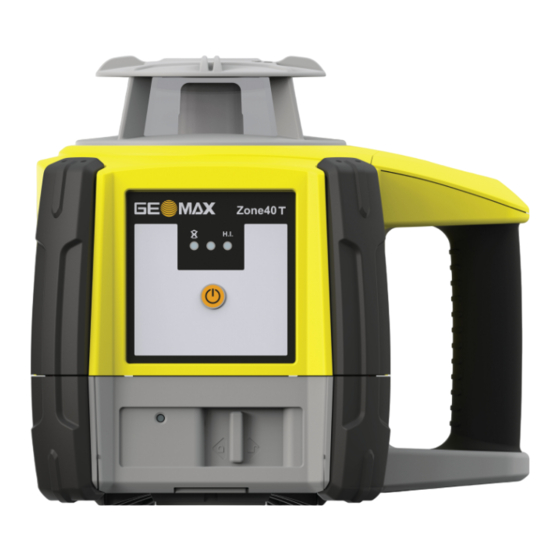
Page 13: Zone40 T Laser Components
Place the Zone40 T on stable ground. Ground vibration and extremely windy conditions can • affect the operation of the Zone40 T. When working in a very dusty environment place the Zone40 T up-wind so the dirt is blown • away from the laser. - Page 14 Tighten the screw on the underside of the tripod to secure the Zone40 T on the tripod. Attach the Zone40 T securely to a tripod or laser trailer, or mount on a stable level surface. • Always check the tripod or laser trailer before attaching the Zone40 T. Make sure all •...
-
Page 15: Operation
Turning on and off Press the Power button to turn on or off the Zone40 T. After turning on: If set up within the 6° self-levelling range, the Zone40 T automatically levels to create an • accurate horizontal plane of laser light. -
Page 16: Automatic Mode
H.I.Alert. Automatic Mode Automatic Mode In Automatic Mode the Zone40 T automatically levels if set up within the 6° self-levelling range. Manual Mode Manual Mode Manual slopes can be created using the Zone40 T together with a manual slope adapter. -
Page 17: Height Of Instrument Alert (H.i.alert) Function
The H.I.Alert monitors the laser. If disturbed, both the X-axis LED and Y-axis LED flash and • the Zone40 T beeps rapidly. To stop the alert turn Zone40 T off and on again. Check the height of the laser before • beginning to work again. -
Page 18: Receiver
Receiver Description The Zone40 T is sold with the ZRB90, ZRP105 or ZRD105 Receiver. ZRB90, Basic Receiver Instrument components part 1 of 2 Keypad Laser reception window Level vials 11190_002 Component Description Front and rear LCD arrow indicate the detectors position. -
Page 19: Zrp105, Pro Receiver
Component Description Battery door Access to the battery compartment. Product label The serial number is located inside the battery compartment. Description of the buttons Power Bandwidth Audio 11192_002 Button Function Power Press once to turn on the receiver. Bandwidth Press to change detection bandwidth. Audio Press to change the audio output. - Page 20 Component Description On-grade Indicates the on-grade position of the laser. Keypad Power, accuracy and volume functions. Instrument components part 2 of 2 Bracket mounting hole Offset notch Product label Battery door 011194_001 Component Description Bracket mounting hole Location to attach the receiver bracket for normal operation. Offset notch Use to transfer reference marks.
-
Page 21: Zrd105, Digital Receiver
Menu Function Indication Changes the brightness of the Red and green LEDs - LED indicators. High/Low/Off Red and Green LEDs change brightness to indicate this parameter. Turns on or off the Laser Green LED is on: Laser low low battery indication on the battery icon function is active. -
Page 22: Applications
1 + 2 011273_001 Step Description Set up the Zone40 T on a tripod. Set up the tripod on a stable surface outside the working area. Attach the receiver to a rod. Turn on the Zone40 T and the receiver. -
Page 23: Batteries
Plug the AC connector into the appropriate AC power source. Connect the charger plug into the charge jack on the Zone40 T battery pack. The small LED next to the charge jack flashes indicating that the Zone40 T is char- ging. - Page 24 Zone40 T to run for a full eight hours. Changing the Li-Ion bat- With the Li-Ion battery pack, the battery indicator on the Zone40 T indicates when the battery tery pack pack is low and must be charged. The charge indicator LED on the Li-Ion battery pack indicates when the battery pack is being charged (flashing slowly) or fully charged (on, not flashing).
- Page 25 28450_001 ☞ The batteries are inserted in the front of the laser. Slide the locking mechanism on the battery compartment to the right. To remove the batteries: Open the battery compartment. Remove the batteries from the battery compartment. To insert the batteries: Insert the batteries into the battery compartment, ensuring that the contacts are facing in the right direction.
-
Page 26: Accuracy Adjustment
30 m (100 ft) X— 011292_001 Align the first axis so that it is square to a wall. Allow the Zone40 T to self-level completely (approximately 1 minute after the Zone40 T begins to rotate). Mark the position of the beam. - Page 27 • The level indicator LED flashes three times, then flashes slowly until level. When the • Zone40 T is level, the level indicator LED is on, but does not flash. The H.I.Alert indicator LED is off. • Adjusting the X-axis Press the left hidden button and right hidden button to increment the laser beam up and down.
-
Page 28: Troubleshooting
After two minutes in the alert con- dition, the unit will shut off auto- matically. Servo limit alert The Zone40 T is tipped too far to All LED flash sequentially. reach a level position. Relevel the Zone40 T within the six degree self- levelling range. - Page 29 With Zone40 T turned on and rotating, press and hold the left hidden button and the right hidden button. Then press the centre hidden button to enable or disable the H.I.Alert function. The Zone40 T beeps once to indicate the change. Troubleshooting...
-
Page 30: Care And Transport
For products for which no container is available use the original packaging or its equivalent. Shipping When transporting the product by rail, air or sea, always use the complete original GeoMax pack- aging, container and cardboard box, or its equivalent, to protect against shock and vibration. - Page 31 compartment. Do not repack until everything is completely dry. Always close the transport con- tainer when using in the field. Cables and plugs Keep plugs clean and dry. Blow away any dirt lodged in the plugs of the connecting cables. Care and Transport...
-
Page 32: Technical Data
Technical Data 10.1 Conformity to National Regulations Labelling Zone40 T GeoMax AG CH-9443 Widnau Complies with 21 CFR 1040.10 and 1040.11 except for conformance with IEC 60825-1 Ed. 3., as described in Laser Notice No. 56, dated May 8, 2019. -
Page 33: Dangerous Goods Regulations
Connect the equipment into an outlet on a circuit different from that to which the receiver • is connected. Consult the dealer or an experienced radio/TV technician for help. • Changes or modifications not expressly approved by GeoMax for compliance could void the user's authority to operate the equipment. Canada CAN ICES-003 B/NMB-003 B Others The conformity for countries with other national regulations has to be approved prior to use and operation. -
Page 34: General Technical Data Of The Product
GeoMax has developed Guidelines on “How to carry GeoMax products” and “How to ship GeoMax products” with Lithium batteries. Before any transportation of a GeoMax product, we ask you to consult these guidelines on our web page (http:// www.geomax-positioning.com/dgr) to ensure that you are in accordance with the IATA Dangerous Goods Regulations and that the GeoMax products can be transported correctly. -
Page 35: Charger And Batteries
☞ Use only high quality alkaline batteries to achieve operating time. Environmental specifica- Temperature tions Operating temperature Storage temperature -20°C to +50°C -40°C to +70°C (-4°F to +122°F) (-40°F to +158°F) Protection against water, dust and sand Protection IP67 (IEC 60529) Dust tight Waterproof to 1 m temporary immersion. - Page 36 996399-1.0.0en Original text (996399-1.0.0en) © 2023 GeoMax AG is part of Hexagon AB. All rights reserved. GeoMax AG Espenstrasse 135 9443 Widnau Switzerland geomax-positioning.com...
Need help?
Do you have a question about the Zone40 T and is the answer not in the manual?
Questions and answers