Table of Contents
Advertisement
Advertisement
Table of Contents

Related Manuals for Jungheinrich ERC-Z12


Summary of Contents for Jungheinrich ERC-Z12
- Page 1 ERC/ERC-Z 12/14/16 10.01- Operating instructions 50126632 06.02...
- Page 2 Used to indicate standard equipment. Used to indicate optional equipment. Our trucks are subject to ongoing development. Jungheinrich reserves the right to alter the design, equipment and technical features of the truck. No guarantee of particular features of the truck should therefore be inferred from the present operating instructions.
-
Page 4: Table Of Contents
Table of contents Correct use and application of the truck Truck description Application ................... B 1 Assemblies ..................B 2 Technical data - standard version ............B 3 Performance data ................B 3 Dimensions ..................B 4 EN standards ..................B 5 Conditions for application .............. - Page 5 Operation Safety regulations governing the operation of the fork lift truck ..E 1 Description of controls and indicating instruments ......E 2 Starting up the truck ................E 6 Operation of the fork lift truck .............. E 8 Safety regulations applicable when operating the truck ...... E 8 Driving, steering, braking ..............
-
Page 6: A Correct Use And Application Of The Truck
A Correct use and application of the truck The “Guidelines for the Correct Use and Application of Industrial Trucks” (VDMA) are included in the scope of delivery for this truck. The guidelines are part of these oper- ating instructions and must always be heeded. National regulations are fully applica- ble. -
Page 8: B Truck Description
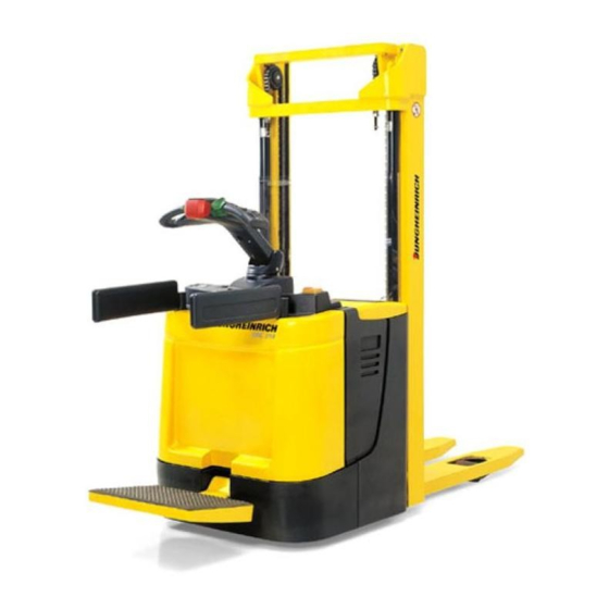
B Truck description Application The truck is an electric pedestrian stacker in four-wheel construction with foldable driver platform. It is designed for transporting and lifting goods on level ground. The wheel arm lift (on- ly for ERC-Z trucks) increases the ground clearance for transport over unevenground. Depending on the design, the hoist frame permits loads to be stacked and retrieved up to a max. -
Page 9: Assemblies
Assemblies Item Designation Item Designation o Keyboard t Wheel arms (CANCODE) o Display instrument o Lifting linkage (Only for wheel-arm- (CANDIS) lifting) t Key switch o Charger t Control shaft t Supporting wheel t Controller t Hinged driver standing platform t Free-view hoist frame t Driven wheel t Master switch... -
Page 10: Technical Data - Standard Version
Technical data - standard version Indication of technical data according to VDI 2198, subject to modification and supplementing. Performance data ERC 12 ERC 14 ERC 16 Designation ERC-Z12 ERC-Z14 ERC-Z16 Q Rated capacity 1,200 1,400 1,600 c Load centre distance Travelling speed 6.0 / 6.0... -
Page 11: Dimensions
Dimensions (all dimensions in mm) ERC 12/ ERC 14/ ERC 16/ Designation ERC-Z12 ERC-Z14 ERC-Z16 Design length of front 856* /888* 856* /888* 856** /888** Height of fork when lowered Design height 1,700 - 2,600 1,700 - 2,600 1,700 - 2,600... -
Page 12: En Standards
EN standards Continuous sound level: 68 dB(A) according to EN 12053 as stipulated in ISO 4871 The continuous sound level is a value averaged according to standard regulations, taking the sound pressure level into account when driving, lifting and idling. The sound pressure level is measured at the ear. -
Page 13: Location Of Instruction Labels And Identification Labels
Location of instruction labels and identification labels Xxxx Xxxxxxx Xxxxxx Xxxxxxxxx Xxxxxx Xxxxxxxxx Xxxxxxxxxxxxxxxxxxx Xxxxxxxxxxxxxxxxxx Xxxxxxxxxx Xxxxxxxxxxxxxxxxx Xxxxxxxxxxxxxxxxxxx Xxxxxxxxx Xxxxxxxxxxxxxxxxxxx xxxxxxxxxx Xxxxxxxxxx Xxxxxxxxxxxxxxxxx xxxxxxxx Xxxxxxx Xxxxxx Xxxxx Xxxxxxxxxxxxxxxx Xxxx Xxxxxxxxxxxxxxxxxx Item Designation Capacity (only ERC-Z) Truck identification plate Attachment point of hooks for transportation by crane Prohibitive sign “Keep away from under the load lifting device”... -
Page 14: Load Capacity
Truck identification plate Xxxx Xxxxxxx Xxxxxx Xxxxxxxxx Xxxxxx Xxxxxxxxx Xxxxxxxxxxxxxxxxxxx Xxxxxxxxxxxxxxxxxx Xxxxxxxxxx Xxxxxxxxxxxxxxxxx Xxxxxxxxxxxxxxxxxxx Xxxxxxxxx Xxxxxxxxxxxxxxxxxxx xxxxxxxxxx Xxxxxxxxxx Xxxxxxxxxxxxxxxxx xxxxxxxx Xxxxxxx Xxxxxx Xxxxx Xxxxxxxxxxxxxxxx Xxxx Xxxxxxxxxxxxxxxxxx Item Designation Item Designation Type Drive power in kW Serial No. Customer no. Rated capacity in kg Min./max. -
Page 15: Load Capacity, Wheel-Arm Lifting Device
Load capacity, wheel-arm lifting device Trucks with a wheel-arm lifting device are provided with an extra label (15) indicating the permissible assignment to wheel-arm lifting device and main lifting device. Label/Order/Inventory/Service No. Item Description Order no. Inventory No. Full Service No. This label contains the Full Service No. -
Page 16: C Transportation And Commissioning
C Transportation and commissioning Transportation by crane Only use lifting equipment with sufficient bearing capacity (loading weight see identi- fication label on truck). If trucks are to be lifted that are provided with a wheel-arm lifting device, be careful not to protrude the lifting cylinders while the truck is being lifted. If the device is com- pletely protruded, there is the risk that the cylinder protection is being released due to overloading. -
Page 17: Moving The Truck With The Drive Unit Inoperative
At trucks with an optionally built-in battery charger, adjust the characteristics (loading cam) (see chapter D). – Load the battery (see chapter D). – If required, check whether the settings of the combined instrument correspond to the battery (see chapter D). –... -
Page 18: D Battery - Servicing, Recharging, Replacement
D Battery - Servicing, recharging, replacement Safety regulations governing the handling of lead-acid batteries The truck must be parked and rendered safe before any operations on batteries are undertaken (refer to chapter E). Servicing staff: Recharging, servicing and replacing of batteries must only be per- formed by qualified personnel. -
Page 19: Battery Type
Battery type Depending on the use, the truck is equipped with different types of batteries. The table below shows the capacity of the batteries and also the combinations used as standard equipment: 24V - 3PzSL - Battery 240Ah 24V - 3PzSL - Battery 270Ah 24V - 3PzSL - Battery 330Ah... -
Page 20: Charging The Battery
Charging the battery As default, the truck is to be loaded with a stationary battery charger. The truck wit- hout wheel-arm lifting device can optionally be supplied with an integrated battery charger. For recharging the battery, the truck has to parked in-doors in a sufficiently ventilated environment. -
Page 21: Recharging The Battery With Integrated Battery Charger (O)
Recharging the battery with integrated battery charger (o) The battery charger must not be opened. If it is damaged, it has to be exchanged. Due to safety reasons, intermediate positions are available between the regulation positions “1” to “6” of the switch (7). If the truck is delivered without battery, an intermediate position is pre-selected as de- fault. - Page 22 Adjusting the charging curve The charging curve can be adjusted by performing the following steps: Connect the battery This permits to use the battery charger as an adjustment aid Turn the adjustment switch to The red LED flashes fast no valid the right (i.e.
- Page 23 The master switch (2) may only be operated with truck and battery charger being swit- ched off. The flashing LED indicates the charging status and/or a fault (flashing codes see ta- ble “LED display”). If the power plug (8) is connected to the mains, all electric functions of the truck are interrupted (electric driving lock).
-
Page 24: Removing And Installing The Battery
Removing and installing the battery – Expose the battery (refer to section 3). The truck must stand horizontally. Batteries with exposed terminals or connectors must be covered with a rubber mat to prevent short-circuits. Place battery connector and battery cable in such a way that they do not get caught within the truck interior when the battery is pulled out. -
Page 25: Remove Battery By Lifting It Upwards (Truck With Wheel-Arm Lifting Device)
Remove battery by lifting it upwards (truck with wheel-arm lifting device) – Withdraw the battery connector (3). The battery cable of the truck must be laterally led outside. While removing the bat- tery, make sure that the cable is not squeezed. –... -
Page 26: Lateral Battery Change (O)
Lateral battery change (o) – Withdraw the battery connector. – Pull the locking mechanism (12) of the battery cover upwards while firmly holding the battery cover (13). – Lift out the battery cover (13) and keep it in a safe location. –... - Page 27 D 10...
-
Page 28: Safety Regulations Governing The Operation Of The Fork Lift Truck
E Operation Safety regulations governing the operation of the fork lift truck Driving permission: The fork lift truck must only be operated by persons who have been trained in the operation of trucks, who have demonstrated to the user or his re- presentative their capability of moving and handling loads, and who have expressly been charged by the user or his representative with the operation of the truck. -
Page 29: Description Of Controls And Indicating Instruments
Description of controls and indicating instruments Item Controls or ERC-Z Function indicating instrument 14/16 12/14/16 respectively Keyboard Code settings (CANCODE) Travel programme enable Display instrument Operating hours meter (CANDIS) Battery capacity display Shows the residual capacity of the battery as well as the accumulated operating hours of the truck. - Page 31 Pos. Controls or ERC-Z Function indicating instrument 14/16 12/14/16 respectively 10 Button - Lifting the lifting device. Lifting the lifting device The lifting speed can be conti- nuously adjusted with this key (adjustment range 8 mm). 11 Button - Lowering the lifting device. Lowering the lifting de- The lowering speed can be vice...
-
Page 33: Starting Up The Truck
Starting up the truck Before starting or operating the truck, or before lifting any loads, the driver has to make sure that nobody is within the danger area. The electronic driving and steering systems automatically control their functions. If an error or fault occurs, the driving and steering functions are stopped. - Page 34 Switching on the truck – Pull up the master switch (13). – Insert the key in the key switch (3) and turn the key clockwise towards the “I” position until reaching the stop. – When a code lock is installed, you must enter an operator code (refer to section 6.6).
-
Page 35: Operation Of The Fork Lift Truck
Operation of the fork lift truck Safety regulations applicable when operating the truck Driving lanes and work areas: Only such lanes and routes that are specially alloca- ted for truck traffic must be used. Unauthorized persons must stay away from work areas. -
Page 36: Driving, Steering, Braking
Driving, steering, braking Be extremely careful when driving and steering, especially when parts of the body protrude from the truck contour. Emergency cut-out – Depress the master switch (13). This will switch off all electric functions. The truck is compulsory braked. Emergency stop When the control shaft (4) is released, the truck is automatically braked (emergency stop). - Page 37 Driving When swivelling the driver’s standing platform (16) upwards, do not reach between the driver’s standing platform and the truck’s side wall. There are three different travelling modes: – Pedestrian-controlled operation: Swivel the safety extensions (17)* inwards and then fold up driver platform (16).
- Page 38 Driving up an incline The load must be transported facing the incline! Safety measures against “rolling down” of the truck: With the controller (8) set to neutral, the service brake is automatically applied after a brief jolt (the controller detects the truck’s rolling down on an incline). The controller (8) is used to release the service brake;...
-
Page 39: Picking Up And Setting Down Loads
Braking by means of the service brake: – Swivel the control shaft (4) into one of the braking ranges “B” or release the control shaft altogether. The drive motor will then be braked by means of the motor brake. When the control shaft is released, it will automatically swivel into the upper braking range “B”. - Page 40 Lifting and lowering Lifting – Press the “Lift the lifting device” button (10) until the desired height has been reached. Lowering – Press the “Lower the lifting de- vice” button (11) until the desired height has been reached. The lifting/lowering speed can be continuously adjusted with this button (adjustment range 8 mm).
- Page 41 Switching matrix / safety switching height ERC / ERC-Z 12 Platform Lifting Speed (km/h) Collision guard button Lifting height with load functions active active Folded up <Sh * Folded up >Sh * Folded out <Sh * Folded out >Sh * ERC / ERC-Z 14/16 Platform Safety Lifting...
- Page 42 Wheel-arm lifting device (only ERC-Z) (t) The “Lift wheel arms” and “Lower wheel arms” can be used to perform the lifting or lowering movement with a fixed speed. To ensure the stability of the truck, the wheel arms will be automatically lowered from a specific lifting height of the fork onwards, depending on the used hoist frame type.
-
Page 43: Safe Parking Of The Truck
Safe parking of the truck If the truck is left unattended, even for only short periods of time, it must be rendered safe. Do not park the truck on slopes! The load lifting device must always be completely lowered. – Park the truck on level ground. –... -
Page 44: Keyboard (Cancode) (O)
Keyboard (CANCODE) (o) The keyboard is provided with a key switch function. It is equipped with a 10-key numeric keypad and two special keys. After entering the correct code the control circuit is switched on. Functions The keyboard can only administer one master code and 600 operator codes. It is possible to assign a unique code to each truck. -
Page 45: Commissioning
Commissioning After switching on the master switch and the key switch the LED (20) lights up steady red also during operation. If the keyboard is used as code switch, the control circuit switches on after entering the correct operator code (factory-set to 2580). LED (20) now lights up steady green. When an incorrect code has been entered, LED (20) light up red for two seconds. -
Page 46: Indicators
Indicators Status displays of the individual LEDs – steady (red) – steady (green) – flashing red – flashing green – off LED (20) steady (red) Truck off (not ready for operation) steady (green) Truck on (operating mode) flashing red Truck with error message flashing green Truck on (master mode) LED (22) steady (green) -
Page 47: Keys
Keys o-key (25) The o-key (25) is always active and has the highest priority. It is used to set the truck from any state to the basic state (truck switched off and not ready for operation) and vice versa. It is exclusively used for switching off or resetting the truck. Set key (21) No function for the operator. - Page 48 Acceleration example Display instrument LED (20) LED (22) LED (23) LED (24) (CANDIS) current green 101 6 setting flashing is displayed changed green 101 8 setting flashing is displayed Parameter Parameter number setting value After entering parameter number 101 and pressing the Set key, the current value 6 is read out and displayed Change the value to 8 and confirm with Set key (21).
-
Page 49: Parameter
Parameter Parameter groups The parameter number is composed of three digits. The first digit designated the parameter group according to table 1. The second and third digits are sequentially numbered from 00 to 99. No. Parameter group 0xx Code lock settings (Codes, travel programme enable, automatic switch-off, etc.) 1xx Travel programme (Acceleration, coasting brake, speed, etc.) - Page 50 Truck parameter list Function Range Default Comments Setting value Setting value Code lock - internal 000 Change master code 0000 - 9999 (LED 22 flashes) Enter the current The length of the master code code determines the 00000 - 99999 length of the operator code.
- Page 51 Function Range Standard Comments Setting value Setting value Code lock - internal 003 Delete operator code 0000 - 9999 (LED 23 flashes) Enter a code 00000 - 99999 Confirm (Set) 000000 - 999999 (LED 24 flashes) Repeat the code entry Confirm (Set) 004 Clear code memory 3265...
- Page 52 Function Range Standard Comments Setting value Setting value Travel programme 101 Acceleration 0 - 9 102 Coasting brake with 0 - 9 enable 104 Drive direction: 0 - 9 Maximum speed 105 Drive direction: 0 - 9 Pedestrian controller speed 108 Fork direction: 0 - 9 Maximum speed...
-
Page 53: Display Instrument (Candis) (O)
Display instrument (CANDIS) (o) The instrument indicates: – Battery discharge condition (LED bars (27)), – Operating hours (LC display (29)). In addition, error messages of the electronic components and parameter changes are displayed. Discharge status indication Depending on the battery type set, switch-on limits for the additional “Warning” (26) and “Stop”... -
Page 54: Discharge Monitor Function
Discharge monitor function With the discharge monitor function enabled, the lifting function switches of when reaching the discharge limit (the Stop LED switches on). Travelling and lowering is still possible. For wet batteries the residual capacity is 20%, for maintenance-free batteries it is 40%. -
Page 55: Fault Location
Fault location This chapter helps the operator to locate and fix simple malfunctions or the results of operating errors him- or herself. The order of the work stated in the table must be ob- served for fault location. Fault Possible cause Remedy Truck does not –... -
Page 56: F Maintenance Of The Fork Lift Truck
F Maintenance of the fork lift truck Operational safety and environmental protection The checks and servicing operations contained in this chapter must be performed in accordance with the intervals as indicated in the servicing checklists. Modifications of fork lift truck assemblies, especially of the safety installations, are not permitted. - Page 57 Work on the electric system: Work on the electric system of the truck must only be performed by personnel specially trained for such operations. Before commencing any work on the electric system, all measures required to prevent electric shocks have to be taken. For battery-operated fork lift trucks, the truck must also be depowe- red by removing the battery plug.
-
Page 58: Servicing And Inspection
Servicing and inspection Thorough and expert servicing is one of the most important preconditions for safe operation of the fork lift truck. The neglect of regular servicing intervals can lead to fork lift truck failure and constitutes a potential hazard to personnel and equipment. The indicated servicing intervals are based on single-shift operation under normal operating conditions. -
Page 59: Maintenance Checklist
Maintenance checklist Maintenance intervals = t W M M M Standard Cold-storage depot = k 1 3 6 12 Chassis/ 1.1 Check all load bearing elements for damage Design: 1.2 Check all bolted connections 1.3 Check platform for correct functioning and damage Drive unit: 2.1 Check the transmission for noises and leakage 2.2 Check the transmission oil level... - Page 60 Maintenance intervals = t W M M M Standard Cold-storage depot = k 1 3 6 12 Electr. 9.1 Check function system: 9.2 Check all cables for secure connection and damage 9.3 Check the fuses for correct amperage 9.4 Check switches and trip cams for proper functioning and seating 9.5 Check contactors and relays, replace wearing parts, if necessary...
-
Page 61: Lubrication Schedule
Lubrication schedule ERC/Z 1,25 - 1,3 l M A = 105 Nm Slide faces Grease nipple Filler neck for hydraulic oil Filler neck Gear oil Drain plug Gear oil Cold store usage 1.25l - 1.3l; Mixing proportion for application in cold-storage depots 1:1 only ERC-Z Filling level see “Check hydraulic oil level”... -
Page 62: Fuels, Coolants And Lubricants
Fuels, coolants and lubricants Handling consumption type material: Consumption type material must always be handled properly. Manufacturer's instructions to be observed. Improper handling is injurious to health, life, and environment. Consumption type ma- terials must be stored in adequate containers. They might be inflammable and, the- refore, must not come into contact with hot components or open fire. -
Page 63: Notes On Maintenance
Notes on maintenance Preparation of the truck for servicing and maintenance operation All required safety measures must be taken to prevent any accidents in the course of the servicing and maintenance operations. The following preparatory operations must be performed: – Park the truck and render it safe (refer to chapter E). –... -
Page 64: Check Hydraulic Oil Level
Check hydraulic oil level – Prepare the truck for servicing and maintenance operations (refer to chapter F, sec- tion 6.1). – Open the front hood (see section 6.2). – Check the hydraulic oil level of the hydraulic tank (see section 5). There are markings on the hydraulic tank (see section 5). -
Page 65: Checking The Electric Fuses
Checking the electric fuses – Prepare the truck for the performance of servicing and maintenance operations (refer to section 6.1). – Open the front cover (refer to section 6.2). – Check all fuses for correct ratings and possible damage according to the table and exchange them, if required. -
Page 66: Recommissioning The Truck
Recommissioning the truck Recommissioning of the truck following the performance of cleaning or maintenance work is permitted only after the following operations have been performed: – Check the horn for proper functioning. – Check the master switch for correct functioning. –... -
Page 67: Recommissioning The Truck
Recommissioning the truck – Thoroughly clean the fork lift truck. – Lubricate the fork lift truck according to the lubrication chart (refer to chapter F). – Clean the battery. Grease the pole screws using pole grease and reconnect the battery. –...
Need help?
Do you have a question about the ERC-Z12 and is the answer not in the manual?
Questions and answers