Table of Contents
Advertisement
Quick Links
Advertisement
Table of Contents
Troubleshooting

Related Manuals for Jungheinrich ESC 316z


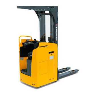
Summary of Contents for Jungheinrich ESC 316z
- Page 1 ESC 316/316z 06.13 - Operating instructions 51314819 11.14 ESC 316 ESC 316z...
- Page 4 Our trucks are subject to ongoing development. Jungheinrich reserves the right to alter the design, equipment and technical features of the system. No guarantee of particular features of the truck should therefore be assumed from the present operating instructions.
- Page 5 Copyright Copyright of these operating instructions remains with JUNGHEINRICH AG. Jungheinrich Aktiengesellschaft Am Stadtrand 35 22047 Hamburg - Germany Tel: +49 (0) 40/6948-0 www.jungheinrich.com...
-
Page 6: Table Of Contents
Table of contents Correct Use and Application ........... General....................Correct application................... Approved application conditions .............. Proprietor responsibilities ................ Adding attachments and/or optional equipment ........Truck Description ..............Application ....................Truck models and rated capacity............. Travel direction definition................. Assemblies and Functional Description........... Assembly Overview ................. - Page 7 Operation ................Safety Regulations for the Operation of the Forklift Truck....... Displays and Controls................Battery discharge indicator ..............Battery discharge monitor................ Preparing the Truck for Operation ............Checks and operations to be performed before starting daily operation . Preparing the truck for operation ............. Checks and operations to be carried out when the truck is operational ..
- Page 8 Servicing and Inspection ................. 124 ESC 316 maintenance checklist.............. 125 10.1 Operating company ................. 125 10.2 Customer service..................126 ESC 316z maintenance checklist ............130 11.1 Operating company ................. 130 11.2 Customer service..................131 Traction Battery Appendix............135 Correct Use and Application..............135 Data plate ....................
-
Page 10: A Correct Use And Application
A Correct Use and Application General The truck must be used, operated and serviced in accordance with the present instructions. All other types of use are beyond its scope of application and may result in damage to personnel, the industrial truck or property. Correct application NOTE The maximum load and load distance are indicated on the capacity plate and must... -
Page 11: Approved Application Conditions
Approved application conditions – Operation in industrial and commercial environments. – Permissible temperature range 5°C to 40°C. – Operation only on secure, level surfaces with sufficient capacity. – Do not exceed the permissible surface and spot load limits on the travel routes. –... -
Page 12: Proprietor Responsibilities
Proprietor responsibilities For the purposes of the present operating instructions the “operating company” is defined as any natural or legal person who either uses the industrial truck himself, or on whose behalf it is used. In special cases (e.g. leasing or renting) the proprietor is considered the person who, in accordance with existing contractual agreements between the owner and user of the industrial truck, is charged with operational duties. -
Page 14: B Truck Description
The ESC 316/316z is designed to transport goods on level surfaces. The wheel arm lift, also called initial lift (ESC 316z only), increases the ground clearance when transporting loads on uneven ground. The truck can lift open bottom or diagonal board pallets beyond the area of the load wheels as well as roll cages. -
Page 15: Travel Direction Definition
Travel direction definition The following determinations have been made for travel direction specification: Item Travel direction Left Drive direction Load direction Right... -
Page 16: Assemblies And Functional Description
Assemblies and Functional Description Assembly Overview Item Description Item Description t Discharge indicator 14 t Armrest t Key switch 15 t Floor plate height adjuster o Control / display unit 16 t Steering wheel o CanCode code lock 17 t Battery o ISM access module 18 t Load wheels 10 t Overhead guard... -
Page 17: Functional Description
Functional Description Safety mechanisms An enclosed, smooth truck geometry with rounded edges ensures safe handling of the truck. The wheels are surrounded by a solid skirt. Activating the Emergency Disconnect switch rapidly cuts out all electrical functions in hazardous situations. The mast grille (o) protects the operator from moving mast parts and the load. - Page 18 Drive system A fixed AC three-phase motor actuates the drive wheel via a bevel spur gearbox. The electronic traction controller ensures smooth drive-motor-speed control and hence smooth starting, powerful acceleration and electrically controlled braking with energy regeneration. The driver can choose from 3 travel programs depending on the load and the environment: from high-performance to energy-saving.
-
Page 19: Technical Specifications
Technical Specifications The technical specifications comply with the German "Industrial Truck Data Sheet" Guidelines. Technical modifications and additions reserved. Performance data ESC316 ESC316z Q Rated capacity 1600 Travel speed 9.1/ 9.1 km/h with / without rated load Lift speed 0.13 / 0.24 0.14 / 0.23 with / without rated load Lower speed... -
Page 20: Dimensions
Dimensions... - Page 21 ESC316 ESC316z Load centre distance Load distance 874 / 796 lowered / raised Wheelbase 1648 1692 / 1514 lowered / raised h1 Mast height retracted 1995 h2 Free lift h3 Lift 2800 h4 Mast height extended 3422 h5 Wheel arm lift (initial lift) Height above overhead 2095 guard...
-
Page 23: Weights
Weights ESC316 ESC316z Net weight excl. battery 1366 1305 Axle loading, laden Drive direction / load direction 1459 / 1228 1432 / 1857 + battery Axle loading, unladen Drive direction / load direction 1891 / 518 1190 / 495 + battery Battery weight Tyre type ESC316... -
Page 24: Mast Versions
Mast versions 1995 2800* 3372 2093 2145 3100 3672 2243 2345 3500 4072 2288 2595 4000 4572 2288 2695 4200 4772 2288 1945 1373 2800* 3372 2093 2095 1523 3100 3672 2243 2295 1723 3500 4072 2288 2545 1973 4000 4572 2288 2645... -
Page 25: En Norms
EN norms Noise emission level – ESC 316/316z: 61 dB(A) in accordance with 12053 as harmonised with ISO 4871. The noise emission level is calculated in accordance with standard procedures and takes into account the noise level when travelling, lifting and when idle. The noise level is measured at the level of the driver's ear. -
Page 26: Conditions Of Use
Conditions of use Ambient temperature – operating at 5°C to 40°C Special equipment and authorisation are required if the truck is to be used continually in conditions of extreme temperature or condensing air humidity fluctuations. Electrical requirements The manufacturer certifies compliance with the requirements for the design and manufacture of electrical equipment, according to EN 1175 "Industrial Truck Safety - Electrical Requirements", provided the truck is used according to its purpose. -
Page 27: Identification Points And Data Plates
Identification points and data plates X.XXXX.XX.XX Item Description Warning: “Do not step under the load handler” Warning: "Do not reach through the mast" Raise / lower wheel arms Capacity plate Multi-Pilot Floor plate adjustment Data plate Test plaque Attachment points for lifting by crane Serial number Model description... -
Page 28: Data Plate
Data plate Item Description Item Description Type Year of manufacture Serial number Load centre (mm) Rated capacity (kg) Output Battery voltage (V) Min./max. battery weight (kg) Net weight w.o. battery (kg) Manufacturer Option Manufacturer’s logo For queries regarding the truck or ordering spare parts always quote the truck serial number (34). -
Page 29: Truck Capacity Plate
Truck capacity plate X.XXXX.XX.XX 3600 1105 The rating plate (45) indicates the maximum capacity Q (in kg) for a given load centre C (in mm) and corresponding lift height H (in mm) for the truck with a horizontal load. Example of how to calculate the maximum capacity: With a load centre distance C of 600 mm and a maximum lift height H of 3600 mm. -
Page 30: C Transport And Commissioning
C Transport and Commissioning Lifting by crane WARNING! Incorrect lifting by crane can result in accidents Improper use or use of unsuitable lifting gear and can cause the truck to fall when being lifted by crane. Prevent the truck from hitting other objects during lifting, and avoid uncontrolled movements. -
Page 31: Transport
Transport WARNING! Accidental movement during transport Improper fastening of the truck and mast during transport can result in serious accidents. Loading must only be performed by specialist personnel trained for this purpose. The specialist personnel must be instructed in securing loads on road vehicles and handling load securing devices. -
Page 32: Using The Truck For The First Time
Using the Truck for the First Time WARNING! The use of unsuitable energy sources can be hazardous Rectified AC current will damage the assemblies (controllers, sensors, motors etc.) of the electronic system. Unsuitable cable connections (too long, insufficient wire cross-section) to the battery (tow cables) can overheat, setting the truck and battery on fire. - Page 33 Wheel flattening If the truck has been parked for a long period, the wheel surfaces may tend to flatten. This flattening has a negative effect on the safety and stability of the truck. Once the truck has covered a certain distance, the flattening will disappear.
-
Page 34: D Battery - Servicing, Recharging, Replacement
D Battery - Servicing, Recharging, Replacement Safety Regulations Governing the Handling of Lead-Acid Batteries Maintenance personnel Batteries may only be charged, serviced or replaced by trained personnel. This operator manual and the manufacturer’s instructions concerning batteries and charging stations must be observed when carrying out the work. Fire Protection Do not smoke and avoid naked flames when handling batteries. - Page 35 The use of unsuitable batteries that have not been approved by Jungheinrich for the truck can lead to a deterioration of the braking system during energy recovery operations and also cause considerable damage to the electrical control system.
-
Page 36: Battery Types
Battery types Depending on the model, the truck will be supplied with different battery types. The following table shows which combinations are included as standard: Battery type Capacity Weight 24 volt battery 3 PzS 465 Ah 380 kg 796 x 210 x 782 mm (LXWXH) The battery weights can be taken from the battery data plate. -
Page 37: Exposing The Battery
Exposing the battery CAUTION! Trapping hazard Make sure there is nothing between the battery cover and the truck when you fit the battery cover. WARNING! An unsecured truck can cause accidents Parking the truck on an incline or with a raised load handler is dangerous and is strictly prohibited. -
Page 38: Charging The Battery
Charging the battery WARNING! The gases produced during charging can cause explosions The battery produces a mixture of nitrogen and hydrogen (electrolytic gas) during charging. Gassing is a chemical process. This gas mixture is highly explosive and must not be ignited. Switch the charging station and truck off first before connecting/disconnecting the charging cable of the battery charging station to/from the battery connector. - Page 39 Charging the battery Requirements – Expose the battery, see "Exposing the battery" on page 36. – Correct charging program set on charger. Procedure • Remove the battery connector (48) from the truck plug (49). • Remove any insulating mats from the battery.
-
Page 40: Battery Removal And Installation
Battery removal and installation WARNING! Accident risk during battery removal and installation Due to the battery weight and acid there is a risk of trapping or scalding when the battery is removed and installed. Note the "Safety regulations for handling acid batteries" section in this chapter. Wear safety shoes when removing and installing the battery. - Page 41 Removing the battery Requirements – Park the truck on a horizontal surface. – Park the truck securely, see "Parking the truck securely" on page 53. – Expose the battery, see "Exposing the battery" on page 36. Tools and Material Required –...
- Page 42 Battery installation Requirements – Park the truck securely, see "Parking the truck securely" on page 53. Tools and Material Required – Battery replacement trolley (o) Procedure • Insert the battery (51) in the truck. Place the battery cable on the tray so that it cannot be severed when the battery is inserted.
- Page 43 Checking the battery acid level Requirements – Park the truck securely, see "Parking the truck securely" on page 53. – Expose the battery, see "Exposing the battery" on page 36. Procedure • Remove the battery connector (48) from the truck. •...
-
Page 44: E Operation
E Operation Safety Regulations for the Operation of the Forklift Truck Driver authorisation The truck may only be used by suitably trained personnel, who have demonstrated to the proprietor or his representative that they can drive and handle loads and have been authorised to operate the truck by the proprietor or his representative. - Page 45 Repairs The operator must not carry out any repairs or alterations to the truck without authorisation and the necessary training to do so. The operator must never disable or adjust safety mechanisms or switches. Hazardous area WARNING! Risk of accidents/injury in the hazardous area of the truck A hazardous area is defined as the area in which people are at risk due to travel or lifting operations of the truck, its load handler or the load.
-
Page 46: Displays And Controls
Displays and Controls... - Page 47 Item Control / Display Function t Shows the battery charge status Battery Discharge Indicator t – Activates the truck by applying the Key switch and key control voltage – Removing the key prevents the truck from being switched on by unauthorised personnel o Replaces the key switch CanCode code lock...
- Page 48 Item Control / Display Function t Adjusts the backrest tilt Backrest adjustment lever...
-
Page 49: Battery Discharge Indicator
Battery discharge indicator When the truck has been released via the key switch, CanCode or ISM, the battery charge status is displayed. The LED colours (60) represent the following conditions: LED colour Charge status Green 40–100% Orange 30–40% Green/orange 20–30% flashes at 1 Hz 0–20% If the LED is red, the load can no longer be lifted. -
Page 50: Battery Discharge Monitor
Battery discharge monitor The standard setting for the battery discharge indicator / discharge monitor is based on standard batteries. When using maintenance-free or special batteries, the display and cut-out points of the battery discharge monitor must be set by manufacturer's service department. If this adjustment is not made, the battery may become damaged due to deep discharge. -
Page 51: Preparing The Truck For Operation
Preparing the Truck for Operation Checks and operations to be performed before starting daily operation WARNING! Risk of accident due to damage to or other defects in the truck and optional features If damage or other truck or attachment (optional equipment) defects are discovered during the following checks, the truck must be taken out of service until it has been repaired. -
Page 52: Preparing The Truck For Operation
Preparing the truck for operation Switching on the truck Requirements – For checks and operations to be performed before starting daily operation, see "Checks and operations to be performed before starting daily operation" on page 50. Procedure • Enter the operator position, see "Entry and exit" on page 55. •... -
Page 53: Checks And Operations To Be Carried Out When The Truck Is Operational
Checks and operations to be carried out when the truck is operational WARNING! Risk of accident due to damage to or other defects in the truck and optional features If damage or other truck or attachment (optional equipment) defects are discovered during the following checks, the truck must be taken out of service until it has been repaired. -
Page 54: Parking The Truck Securely
Parking the truck securely WARNING! An unsecured truck can cause accidents Parking the truck on an incline, without the brakes applied or with a raised load or load handler is dangerous and is strictly prohibited. Park the truck on a level surface. In special cases the truck may need to be secured with wedges. - Page 55 Parking the truck securely Procedure • Park the truck on a level surface. • Fully lower the load handler (61): • Apply the “wheel arm lower” button (55) . • Press the Multi-Pilot (12) in the arrow direction. • Set the drive wheel to “Straight ahead”. •...
-
Page 56: Entry And Exit
Entry and exit Requirements – Load handler fully lowered. Procedure Always enter and exit the truck facing the load direction. • To enter and exit, hold onto the handle (62). • Enter or leave the truck. CAUTION! No more than one person may operate the truck at a time. -
Page 57: Adjusting The Floor Plate Height
Adjusting the floor plate height Procedure • Sit down on the driver’s seat. • Press and hold down on the floor plate height adjustment button (15). The floor plate can now be adjusted. • Set the floor plate (63) to the correct height by standing on it / discharging it. •... -
Page 58: Adjusting The Driver's Seat
Adjusting the driver’s seat CAUTION! An unsecured driver's seat can cause injury An unsecured driver's seat can slide out of its guide during travel, resulting in accidents. The driver's seat must be locked in position. Do not adjust the driver’s seat while travelling. Adjusting the driver’s seat Procedure •... -
Page 59: Industrial Truck Operation
Industrial Truck Operation Safety regulations for truck operation Travel routes and work areas Only use lanes and routes specifically designated for truck traffic. Unauthorised third parties must stay away from work areas. Loads must only be stored in places specially designated for this purpose. The truck must only be operated in work areas with sufficient lighting to avoid danger to personnel and materials. - Page 60 Travel visibility The operator must look in the direction of travel and must always have a clear view of the route ahead. If the truck is carrying loads that affect visibility, the truck must travel against the load direction. If this is not possible, a second person must walk alongside the truck as a lookout to observe the travel route while maintaining eye contact with the operator.
- Page 61 Negotiating lifts, loading ramps and docks Lifts may only be negotiated if they have sufficient capacity, are suitable for driving on and authorised for truck traffic by the owner. The driver must satisfy himself of the above before entering these areas. The truck must enter lifts with the load in front and must take up a position which does not allow it to come into contact with the walls of the lift shaft.
-
Page 62: Emergency Disconnect
Emergency Disconnect CAUTION! Applying maximum braking can result in accidents Applying the Emergency Disconnect switch during travel will cause the truck to decelerate to a halt at maximum force. This may cause the load to slide off the load handler. There is a higher risk of accidents and injury. Do not use the Emergency Disconnect switch as a service brake. - Page 63 Press the Emergency Disconnect switch Procedure • Press the Emergency Disconnect (13). All electrical functions are deactivated. The truck brakes to a halt. Press the Emergency Disconnect switch on in emergencies. Releasing the Emergency Disconnect switch Procedure • Pull the Emergency Disconnect switch (13) to unlock it. All electrical functions are enabled and the truck is operational again (provided the truck was operational before the Emergency Disconnect was pressed).
-
Page 64: Travel
Travel WARNING! Collision hazard when operating the truck Collisions with personnel and equipment can result if the truck is operated with open panels. Do not operate the truck unless the panels and covers are closed and properly locked. Requirements – Start up the truck, see "Preparing the truck for operation" on page 51. Procedure •... - Page 65 4.3.1 Changing direction during travel CAUTION! Danger when changing direction during travel Changing direction during travel causes the truck to decelerate rapidly. When the truck changes direction, it can start travelling at high speed in the opposite direction unless the Multi-Pilot is released in time. After setting off in the opposite direction, apply the Multi-Pilot gently or not at all.
-
Page 66: Steering
Steering Requirements – Start up the truck, see "Preparing the truck for operation" on page 51. Procedure • Turn the steering wheel (16) to the left or right. The wheel position is indicated on the display (7) (o). The truck is steered in the required direction. -
Page 67: Brakes
Brakes WARNING! Accident risk while braking The truck’s braking response depends largely on the floor condition and the type of surface. The truck’s braking distance increases when the ground is wet or dirty. The operator must be aware of floor conditions and take them into account when braking. - Page 68 4.5.1 Deadman button The deadman switch (20) must be pressed to lift, lower or travel. If the deadman switch is released during travel, the truck decelerates at the maximum rate until it stops. If the deadman switch is released during lifting or lowering, the respective function cuts out immediately.
-
Page 69: Load Handler Raise/Lower
Load handler raise/lower WARNING! Accident risk when lifting and lowering Other people can be injured in the truck's hazardous area. The hazardous area is defined as the area in which people are at risk from the movement of the truck including the load handler, etc. This also includes areas which can be reached by falling loads, operating equipment, etc. - Page 70 4.6.1 Raising the load handler Requirements – Prepare the truck for operation, see "Preparing the truck for operation" on page 51. – Deadman switch pressed, see page 67. Procedure • Pull the Multi-Pilot (12) in the arrow direction until you reach the required lift height.
- Page 71 4.6.3 Raising the wheel arms Wheel arm lift, also known as initial lift (ESC 316z only), increases the ground clearance when transporting goods on uneven surfaces. Requirements – Prepare the truck for operation, see "Preparing the truck for operation" on page 51.
- Page 72 Press down on the button until the wheel arms are fully lowered. The wheel arms are lowered. Safety height on the ESC 316z To ensure the operational stability of the truck the wheel arms must first be lowered beyond a load handler lift height of approx. 1.80 m before you can continue lifting.
-
Page 73: Lifting, Transporting And Depositing Loads
Lifting, transporting and depositing loads WARNING! Unsecured and incorrectly positioned loads can cause accidents. Before lifting a load unit, the driver must make sure that it has been correctly palletised and does not exceed the truck’s capacity. Instruct other people to move out of the hazardous area of the truck. Stop working with the truck if people do not leave the hazardous area. - Page 74 4.7.1 Raising a load Requirements – Load correctly palletised. – Load weight matches the truck's capacity. – Load handler evenly loaded for heavy loads. Procedure • Drive the truck carefully up to the pallet. • Drive the load handler slowly into the pallet until the pallet is against the back of the load handler (see graphic to the right).
- Page 75 4.7.2 Transporting loads Requirements – Load raised correctly. – Mast lowered for transport (approx. 150 - 200 mm above the ground). – Good ground conditions. Procedure • Accelerate and decelerate with care. • Adapt your travel speed to the conditions of the route and the load you are transporting.
-
Page 76: Troubleshooting
Troubleshooting This chapter enables the operator to localize and rectify basic faults or the results of incorrect operation himself. When trying to locate a fault, proceed in the order shown in the remedy table. If, after carrying out the following remedial action, the truck cannot be restored to operation or if a fault in the electronics system is displayed with a corresponding error code, contact the manufacturer’s service department. -
Page 77: Truck Does Not Start
Truck does not start Possible Cause Remedy Battery connector not inserted Check the battery connector and insert if necessary Emergency Disconnect switch pressed Release the Emergency Disconnect switch, see page 61 Key switch set to O Set the key switch to “I” Deadman switch not pressed Press deadman switch Battery charge too low... -
Page 78: Operating The Truck Without Its Own Drive System
Operating the truck without its own drive system WARNING! Accidental truck movement When the brakes are de-activated the truck must be parked on a level surface, since the brakes are no longer effective. Do not release the brake on slopes or inclines. - Page 79 Activating the brake Procedure • Use wedges to prevent the truck from moving. • Unscrew the two M5x45 screws (64) again. CAUTION! Open covers can cause injury and accidents The covers (battery cover, side panels, drive compartment cover etc.) must be closed during operation.
-
Page 80: Load Handler Emergency Lowering
Load handler emergency lowering WARNING! Lowering the load handler can result in injuries The hazardous area is defined as the area in which people are at risk from the mast, the load handler or the load. This also includes areas which can be reached by falling loads or lowering operating equipment. - Page 81 Load handler emergency lowering Requirements – Load handler is not in the rack. – 3 mm diameter pin, tool etc. Procedure • Fully lower the floor plate (63), see "Adjusting the floor plate height" on page 56. • Remove the screws (65) from the seat cover (66).
-
Page 82: Optional Equipment
Optional equipment Display and control unit 60 74 Item Description STOP Parking brake applied WARNING Displays the current steer angle (drive wheel direction) Steer mode, displays possible travel directions Time display (hours: minutes) Battery charge status Discharge indicator Set travel speed for current profile (max = 5 bars) Slow travel activated (reduced travel speed) Profile number (travel profile 1, 2 or 3) Deadman button not pressed... -
Page 83: Setting The Time
Setting the time Setting the time (73) Procedure • Press the Shift key (84) for 8 secs. until the "Set Clock Time" menu is displayed. • Set the time with the Up (82) and Down (86) keys. • Confirm with the Shift key (84). •... -
Page 84: Keypad (Cancode) (O)
Keypad (CanCode) (o) 8.3.1 Code lock The code lock allows a user or group of users to assign an individual user code. Travel programs can also be assigned to the individual user codes. The user code is configured with a master code and is described in the following sections in this chapter. - Page 85 The keypad consists of 10 digit keys, a Set key (90) and a o key (92) Digit keys The digit keys are used to enter the user or master code and select the travel program. The green LEDs of the digit keys 1, 2 and 3 (87, 88, 89) show the travel program setting.
- Page 86 8.3.2 Preparing the truck for operation with the keypad (CanCode) Preparing the truck for operation by entering a valid operator code Procedure • Pull the Emergency Disconnect to unlock it, see "Emergency Disconnect" on page 61. The LED (91) lights up red. •...
- Page 87 8.3.4 Changing the master code To change the length of the master code you must follow the procedure in "Choose length of the new master code (4-6 digit) and add user codes", see "Choose length of the new master code (4-6 digit) and add user codes" on page 95. If there are still user codes stored in the code lock, the master code to be changed must be the same length as the saved user codes.
- Page 88 Error displays changing the master code For the following events the LED (91) flashes red: Cause Remedy – New master code is already – Switch off the truck, see "Switching off the truck occupied by a user code with the keypad (CanCode)" on page 85. –...
- Page 89 8.3.5 Add operator code Requirements – To prepare the truck for operation, see "Preparing the truck for operation with the keypad (CanCode)" on page 85. Procedure • Press the O key (92). • Enter the valid master code with the digit keys. When you enter the valid master code the LED (91) flashes green.
- Page 90 Error displays adding a user code For the following events the LED (91) flashes red: Cause Remedy – The user code entered is not – Switch off the truck, see "Switching off the truck the same length as the with the keypad (CanCode)" on page 85. master code –...
- Page 91 8.3.6 Change operator code Requirements – To prepare the truck for operation, see "Preparing the truck for operation with the keypad (CanCode)" on page 85. Procedure • Press the O key (92). • Enter the valid master code with the digit keys. When you enter the valid master code the LED (91) flashes green.
- Page 92 Error displays changing a user code For the following events the LED (91) flashes red: Cause Remedy – The user code entered is not – Switch off the truck, see "Switching off the truck the same length as the with the keypad (CanCode)" on page 85. master code –...
- Page 93 8.3.7 Delete individual user codes Requirements – To prepare the truck for operation, see "Preparing the truck for operation with the keypad (CanCode)" on page 85. Procedure • Press the O key (92). • Enter the valid master code with the digit keys. When you enter the valid master code the LED (91) flashes green.
- Page 94 Error displays deleting individual user codes For the following events the LED (91) flashes red: Cause Remedy – The user code entered is not – Switch off the truck, see "Switching off the truck the same length as the with the keypad (CanCode)" on page 85. master code –...
- Page 95 8.3.8 Delete all user codes, Requirements – To prepare the truck for operation, see "Preparing truck operation with keypad (CanCode)" on page 85. Procedure • Press the O key (92). • Enter the valid master code with the digit keys. When you enter the valid master code the LED (91) flashes green.
- Page 96 8.3.9 Choose length of the new master code (4-6 digit) and add user codes The master code is factory set to a four-digit entry: If necessary, the four-digit master code can be changed to a five or six-digit entry. Before the master code length can be changed, all user codes must be deleted.
- Page 97 8.3.10 Setting the automatic truck cutout (timeframe) Requirements – To prepare the truck for operation, see "Preparing the truck for operation with the keypad (CanCode)" on page 85. Procedure • Press the O key (92). • Enter the valid master code with the digit keys. When you enter the correct master code the LED (91) flashes green.
- Page 98 Error displays setting the automatic cutout period of the truck For the following events the LED (91) flashes red: Cause Remedy – Cutout time entered is out of – Switch off the truck, see "Switching off the truck range with the keypad (CanCode)" on page 85. –...
- Page 99 8.3.11 Assigning the travel program The travel programs are fixed to the user code and can be released or blocked with a configuration code. The configuration code can also be used to assign a starting travel program to each user code. The starting travel program is the travel program that is activated when the truck is switched on and is displayed by the (87,88,89) LEDs.
- Page 100 Specifying a configuration code: Setting Description – Travel program 1 is blocked for the user code selected 1st digit – Travel program 1 is enabled for the user code selected – Travel program 2 is blocked for the user code selected 2nd digit –...
- Page 101 Adapting the travel program configuration to the user code Procedure • Press the O key (92). • Enter the valid master code with the digit keys. When you enter the valid master code the green LED (91) flashes green. • Enter the parameters 0-2-4 with the digit keys. •...
-
Page 102: Ism Access Module (O)
Error displays configuring the travel programs For the following events the LED (91) flashes red: Cause Remedy – Blocked travel program – Switch off the truck, see "Switching off the truck defined as start travel with the keypad (CanCode)" on page 85. program –... -
Page 104: F Industrial Truck Maintenance
F Industrial Truck Maintenance Operational Safety and Environmental Protection The checks and servicing operations contained in this chapter must be performed in accordance with the maintenance checklist service intervals. WARNING! Risk of accidents and component damage Any modification to the truck, in particular the safety mechanisms, is prohibited. Exception: Operating companies should only make changes or have changes made to powered industrial trucks if the truck manufacturer is no longer operating in the field and there is no successor to the business;... -
Page 105: Maintenance Safety Regulations
Maintenance Safety Regulations Maintenance and repair personnel The manufacturer has a service department specially trained for these tasks. A maintenance contract with the manufacturer will ensure trouble-free operation. Truck maintenance and repair work must only be carried out by specially trained personnel. -
Page 106: Working On The Electrical System
Working on the electrical system WARNING! Electrical current can cause accidents Make sure the electrical system is voltage-free before starting work on it. The capacitors in the controller must be completely discharged. The capacitors are completely discharged after approximately 10 minutes. Before starting maintenance on the electrical system: Only suitably trained electricians may operate on the truck's electrical system. -
Page 107: Hydraulic System
Hydraulic system WARNING! Leaky hydraulic systems can result in accidents Hydraulic oil can escape from leaky and faulty hydraulic systems. Report any defects immediately to your supervisor. Mark defective truck and take out of service. Do not return the industrial truck to service until you have identified and rectified the fault. -
Page 108: Lift Chains
Lift Chains WARNING! Non-lubricated and incorrectly cleaned lift chains can cause accidents Lift chains are safety-critical parts. They must not contain any serious contamination. Lift chains and pivot pins must always be clean and well lubricated. Lift chains should only be cleaned with paraffin derivatives e.g. petroleum or diesel fuels. -
Page 109: Lubricants And Lubrication Schedule
Lubricants and Lubrication Schedule Handling consumables safely Handling consumables Consumables must always be handled correctly. Follow the manufacturer’s instructions. WARNING! Improper handling is hazardous to health, life and the environment Consumables can be flammable. Keep consumables away from hot components and naked flames. Always keep consumables in prescribed containers. - Page 110 WARNING! Improper handling of oils can be hazardous Oils (chain spray / hydraulic oil) are flammable and poisonous. Dispose of used oils in accordance with regulations. Store used oil safely until it can be disposed of in accordance with regulations. Do not spill oil.
-
Page 111: Lubrication Schedule
Lubrication Schedule A + B 1,05 l g Contact surfaces Cold-store application s Grease nipple a Transmission oil drain plug c Hydraulic oil drain plug Hydraulic oil filler plug 1 Compound ratio for cold store usage 1:1... -
Page 112: Consumables
The Jungheinrich hydraulic oil can only be obtained from the Jungheinrich service department. The use of named alternative hydraulic oils is not prohibited but may lead to a decline in functionality. The Jungheinrich hydraulic oil may be mixed with one of the named alternative hydraulic oils. -
Page 113: Maintenance And Repairs
Maintenance and repairs Preparing the truck for maintenance and repairs Procedure • Park the truck securely, see "Parking the truck securely" on page 53. • Disconnect the battery to prevent the truck from being switched on accidentally. Lifting and jacking up the truck safely WARNING! Lifting and jacking up the truck safely In order to raise the truck, the lifting gear must only be secured to the points specially... -
Page 114: Cleaning
Cleaning 4.3.1 Cleaning the truck CAUTION! Fire hazard Do not use flammable liquids to clean the industrial truck. Disconnect the battery before starting cleaning work. Carry out all necessary safety measures to prevent sparking before cleaning (e.g. by short-circuiting). CAUTION! Risk of component damage when cleaning the truck Cleaning with a pressure washer can result in malfunctions due to humidity. - Page 115 Cleaning the truck Requirements – Prepare the truck for maintenance and repairs (see "Preparing the truck for maintenance and repairs" on page 112). Tools and Material Required – Water-based solvents – Sponge or cloth Procedure • Clean the surface of the truck with water-based solvents and water. Use a sponge or cloth to clean.
- Page 116 4.3.2 Cleaning the electrical system assemblies CAUTION! Risk of electrical system damage Cleaning the assemblies (controllers, sensors, motors etc.) of the electronic system with water can damage the electrical system. Do not clean the electrical system with water. Clean the electrical system with weak suction or compressed air (use a compressor with a water trap) and not a conductive, anti-static brush.
-
Page 117: Drive Compartment Cover Disassembly/Assembly
Drive compartment cover disassembly/assembly Remove drive compartment cover Requirements – Prepare the truck for maintenance and repairs (see "Preparing the truck for maintenance and repairs" on page 112). Tools and Material Required – Allen key Procedure Hold onto the cover (93) when removing the screws. -
Page 118: Checking The Hydraulic Oil Level
Checking the hydraulic oil level Checking hydraulic level replenishing Requirements – Fully lower the load handler. – Prepare the truck for maintenance and repairs, see "Preparing the truck for maintenance and repairs" on page 112. Procedure • Remove the drive compartment cover, see page 116. -
Page 119: Tightening The Wheel Nuts
Tightening the wheel nuts The wheel nuts on the drive wheel must be retightened in accordance with the maintenance intervals indicated in the maintenance checklist, see "Servicing and Inspection" on page 124. Tightening the wheel nuts Requirements – Prepare the truck for maintenance and repairs, see "Preparing the truck for maintenance and repairs"... -
Page 120: Checking Electrical Fuses
Checking electrical fuses Check fuses Requirements – Truck prepared for maintenance and repairs. Procedure • Fold up the arm rest. • Check the fuse ratings against the table and replace if necessary. • Close the armrest. The fuses are now checked. F15 F1 6F1 9F22 3F1 F17 Description To protect... -
Page 121: Restoring The Truck To Service After Maintenance And Repairs
Restoring the truck to service after maintenance and repairs Procedure • Thoroughly clean the truck, see page 113. • Lubricate the truck according to the lubrication diagram, see page 110. • Clean the battery, grease the terminals and connect the battery. •... -
Page 122: Decommissioning The Industrial Truck
Decommissioning the industrial truck If the truck is to be out of service for more than a month, it must be stored in a frost- free and dry room. All necessary measures must be taken before, during and after decommissioning as described hereafter. When the truck is out of service it must be jacked up so that all the wheels are clear of the ground. -
Page 123: Restoring The Truck To Service After Decommissioning
Restoring the truck to service after decommissioning Procedure • Thoroughly clean the truck, see "Cleaning" on page 113. • Lubricate the truck according to the lubrication schedule, see "Consumables" on page 111. • Clean the battery, grease the terminals and connect the battery. •... -
Page 124: Safety Tests To Be Performed At Intervals And After Unusual Incidents
Safety tests to be performed at intervals and after unusual incidents Perform a safety check in accordance with national regulations. The manufacturer recommends the truck be checked to FEM guideline 4.004. The manufacturer has a service department specially trained for these tasks. The truck must be inspected at least annually (refer to national regulations) or after any unusual event by a qualified inspector. -
Page 125: Servicing And Inspection
Servicing and Inspection WARNING! Risk of accident due to neglected maintenance Failure to perform regular servicing can lead to truck failure and poses a potential hazard to personnel and equipment. Thorough and expert servicing is one of the most important requirements for the safe operation of the industrial truck. -
Page 126: Esc 316 Maintenance Checklist
ESC 316 maintenance checklist 10.1 Operating company 10.1.1 Standard equipment Brake system W A B C Test brakes. Electrical system W A B C Test warning and safety devices in accordance with operating instructions. Test Emergency Disconnect switch. Power supply W A B C Check battery cable connections are secure, grease terminals if necessary. -
Page 127: 10.2 Customer Service
10.2 Customer service 10.2.1 Standard equipment Brake system W A B C Test brakes. Check the air gap of the magnetic brake. Electrical system W A B C Test cable and motor attachments. Test warning and safety devices in accordance with operating instructions. - Page 128 Chassis and Superstructure W A B C Check chassis and screw connections for damage. Check doors and/or covers. Check labels are legible and complete. Test adjustable floor board and make sure it is secure. Check the operator position attachment. Check attachment and setting function of the driver's seat. Check condition of the driver’s seat.
- Page 129 Steering W A B C Test electric steering and its components. Check steering head bearings, steering play and steering toothing or steering chain. Lubricate steering gear teeth or steering chain.
- Page 130 10.2.2 Optional equipment Aquamatik Power supply W A B C Test Aquamatik plug, hose connections and float and check for leaks. Test flow indicator and check for leaks. Battery refill system Power supply W A B C Test battery refill system and check for leaks. Data recorder Electrical system W A B C...
-
Page 131: Esc 316Z Maintenance Checklist
ESC 316z maintenance checklist 11.1 Operating company 11.1.1 Standard equipment Brake system W A B C Test brakes. Electrical system W A B C Test warning and safety devices in accordance with operating instructions. Test Emergency Disconnect switch. Power supply... -
Page 132: 11.2 Customer Service
11.2 Customer service 11.2.1 Standard equipment Brake system W A B C Test brakes. Check the air gap of the magnetic brake. Electrical system W A B C Test cable and motor attachments. Test warning and safety devices in accordance with operating instructions. - Page 133 Chassis and Superstructure W A B C Check chassis and screw connections for damage. Check doors and/or covers. Check labels are legible and complete. Test adjustable floor board and make sure it is secure. Check the operator position attachment. Check attachment and setting function of the driver's seat. Check condition of the driver’s seat.
- Page 134 Agreed performance levels W A B C Carry out a test run with rated load, if necessary with a customer- specific load. Lubricate truck according to the lubrication schedule. Demonstration after servicing. Steering W A B C Test electric steering and its components. Check steering head bearings, steering play and steering toothing or steering chain.
- Page 135 11.2.2 Optional equipment Aquamatik Power supply W A B C Test Aquamatik plug, hose connections and float and check for leaks. Test flow indicator and check for leaks. Battery refill system Power supply W A B C Test battery refill system and check for leaks. Data recorder Electrical system W A B C...
-
Page 136: G Traction Battery Appendix
G Traction Battery Appendix Correct Use and Application Failure to observe the operating instructions, carrying out repairs with non-original spare parts, tampering with the battery or using electrolyte additives will invalidate the warranty. Observe the instructions for maintaining the safety rating during operation for batteries in accordance with Ex I and Ex II (see relevant certification). -
Page 137: Safety Instructions, Warning Indications And Other Notes
Safety Instructions, Warning Indications and other Notes Used batteries must be treated as hazardous waste. These batteries are marked with the recycling symbol and the sign showing a crossed-out rubbish bin, and should not be disposed of with ordinary household waste. waste. -
Page 138: Lead Acid Batteries With Armour Plated Cells And Liquid Electrolyte
Lead acid batteries with armour plated cells and liquid electrolyte Description Jungheinrich traction batteries are lead acid batteries with armour plated cells and liquid electrolyte. The names of the traction batteries are PzS, PzB, PzS Lib and PzM. Electrolyte The rated density of the electrolyte assumes a temperature of 30°C and the rated electrolyte level is fully charged. -
Page 139: Operation
Operation 4.2.1 Commissioning unfilled batteries The operations required must be carried out by the manufacturer's customer service department or a customer service organisation authorised by the manufacturer. 4.2.2 Commissioning filled and charged batteries Checks and operations to be performed before starting daily work Procedure •... - Page 140 4.2.4 Charging the battery WARNING! The gases produced during charging can cause explosions The battery gives off a mixture of oxygen and hydrogen (electrolytic gas) during charging. Gassing is a chemical process. This gas mixture is highly explosive and must not be ignited. Always disconnect the charger and truck before connecting or disconnecting the charger and battery.
- Page 141 The electrolyte temperature rises by approx. 10 K during charging. Charging should therefore only begin when the electrolyte temperature is below 45°C. The electrolyte temperature of batteries must be at least +10°C before charging. Otherwise the battery will not charge correctly. Below 10°C the battery is insufficiently charged with standard charging systems.
-
Page 142: Servicing Lead-Acid Batteries With Armour Plated Cells
Servicing lead-acid batteries with armour plated cells Water quality The quality of the water used to fill up electrolyte must correspond to purified or distilled water. Purified water can be produced through distillation or ion exchangers and is then suitable for the production of electrolyte. 4.3.1 Daily –... -
Page 143: Pzv And Pzv-Bs Lead-Acid Batteries With Sealed Armour Plated Cells
PzV and PzV-BS lead-acid batteries with sealed armour plated cells Description PzV batteries are sealed batteries with fixed electrolytes, to which no water can be added over the entire lifespan of the battery. Relief valves are used as plugs which are destroyed when opened. -
Page 144: Operation
Operation 5.2.1 Commissioning Checks and operations to be performed before starting daily work Procedure • Make sure the battery is in physically good condition. • Make sure the terminals are correct (positive to positive and negative to negative) and check that contacts on the battery terminal conducting system are secure. •... - Page 145 NOTE Charging the battery incorrectly can result in material damage. Incorrect battery charging can result in overloading of the electric wires and contacts, hazardous gas formation and electrolyte leakage from the cells. Always charge the battery with DC current. All DIN 41773 charging procedures are permitted in the format approved by the manufacturer.
- Page 146 Charging the battery Requirements – Electrolyte temperature between +15°C and 35°C Procedure • Open or take off the tray lid or covers from the battery compartment. • Connect the battery to the switched off charger, ensuring the terminals are connect (positive to positive and negative to negative).
-
Page 147: Servicing Pzv And Pzv-Bs Lead-Acid Batteries With Sealed Armour Plated Cells
Servicing PzV and PzV-BS lead-acid batteries with sealed armour plated cells Do not add water! 5.3.1 Daily – Charge the battery after each discharge. 5.3.2 Weekly – Visually inspect for dirt and physical damage. 5.3.3 Every three months – Measure and record the overall voltage. –... -
Page 148: Aquamatik Water Replenishment System
Aquamatik water replenishment system Water replenishment system design > 3 m Water container Tap connection with ball cock Flow indicator Shut-off cock Locking coupling Battery lock connector... -
Page 149: Functional Description
Functional Description The Aquamatik water replenishment system is used to adjust the rated electrolyte level automatically on traction batteries for industrial trucks. The battery cells are interconnected through hoses and are attached to the water supply (e.g. water container) through a plug connection. When the shut-off cock is opened all the cells are filled with water. -
Page 150: Filling Time
Filling time The filling time for a battery depends on the electrolyte level, the ambient temperature and the filling pressure. Filling ends automatically. The water supply line must be disconnected from the battery when the water has been filled. Water quality The quality of the water used to fill up electrolyte must correspond to purified or distilled water. -
Page 151: Cleaning Measures
Cleaning measures The plug systems must only be cleaned with purified water in accordance with DIN 43530-4. No parts of the plugs must come into contact with solvent-based materials or soap. 6.10 Service mobile vehicle Mobile water filling vehicle with pump and filling gun to fill individual cells. The immersion pump in the container generates the necessary filling pressure. -
Page 152: Electrolyte Circulation
Electrolyte circulation Functional Description Electrolyte circulation ensures the supply of air during charging to mix the electrolyte, thereby preventing any acid layer, shortening the charge time (charge factor approx. 1.07) and reducing the formation of gas during charging. The charger must be suitable for the battery and electrolyte circulation. - Page 153 NOTE If an installed electrolyte circulation system is seldom used or not used at all, or if the battery is subjected to severe temperature fluctuations, the electrolyte may flow back into the hose system. Attach a separate coupling system to the air inlet line, such as: locking coupling on the battery side and through-coupling on the air supply side.
-
Page 154: Cleaning Batteries
Cleaning batteries Batteries and trays must be cleaned in order to – maintain cell insulation and protect cells from ground or external conductive parts. – Avoid damage from corrosion and stray currents. – Avoid excessive and varying automatic discharge of the individual cells or block batteries due to stray currents. - Page 155 Cleaning the battery with a high pressure cleaner Requirements – Cell connectors tight, plugged in securely – Cell plugs closed Procedure • Follow the high pressure cleaner's user instructions. • Do not use any cleaning additives. • Observe the permissible cleaning device temperature setting of 140°C. This generally ensures that the temperature does not exceed 60°C at a distance of 30cm behind the outlet nozzle.
-
Page 156: Storing The Battery
Storing the battery NOTE The battery should not be stored for longer than 3 months without charging as otherwise it will no longer be functional. If the battery is to be taken out of service for a long period, it should be stored fully charged in a dry room protected from frost.
Need help?
Do you have a question about the ESC 316z and is the answer not in the manual?
Questions and answers