Table of Contents
Advertisement
Quick Links
Advertisement
Table of Contents

Related Manuals for Jungheinrich ETM/V 214


Summary of Contents for Jungheinrich ETM/V 214
- Page 1 ETM/V 214/216 10.03 - Operating instructions 50314468 10.03...
- Page 2 Important Information for Transport and Assembly of Hoist Frames for Reach Trucks Transport Depending on the height of the hoist frame and local conditions three different types of lifts may be undertaken: – Standing with assembled hoist frame (for low heights) –...
- Page 4 Used to indicate standard equipment. Used to indicate optional equipment. Our trucks are subject to ongoing development. Jungheinrich reserves the right to alter the design, equipment and technical features of the truck. No guarantee of particular features of the truck should therefore be inferred from the present operating instructions.
-
Page 6: Table Of Contents
Technical Data Standard Design ............B 7 Performance Data ................B 7 Dimensions ..................B 7 Standard Hoist Frames ETM/V 214/216 ..........B 9 EN Standards ..................B 11 Condition for Use ................B 11 Identification Points and Data Plates ..........B 12 Data plate, truck .................. - Page 7 Operation Safety Regulations for the Operation of Fork Lift Trucks ....E 1 Description of Operating and Display Elements ......... E 2 Starting the Truck ................E 6 How to use the safety belt (o) ............E 8 Preparation for Use ................E 10 Emergency Stop Device ..............
- Page 8 Operational Safety and Environmental Protection ......F 1 Safety Regulations for Mantenance ............ F 1 Maintenance and Inspection ............... F 3 Maintenance Check List ETM/V 214/216 ........... F 4 Lubrication Schedule ETM/V 214/216 ..........F 6 Operating Fluids .................. F 7 Tank Capacity ETM/V 214/216 ............
-
Page 10: A Regulatory Use Of Machine
A Regulatory Use of Machine The document „Guidelines for the Regulatory and Correct Use of Materials Handling Equipment“ (VDMA) is part of the delivery of this vehicle (VDMA). It forms part of the Operator Manual and its contents should be carefully observed. National regulations shall apply in their entirety. -
Page 12: B Truck Description
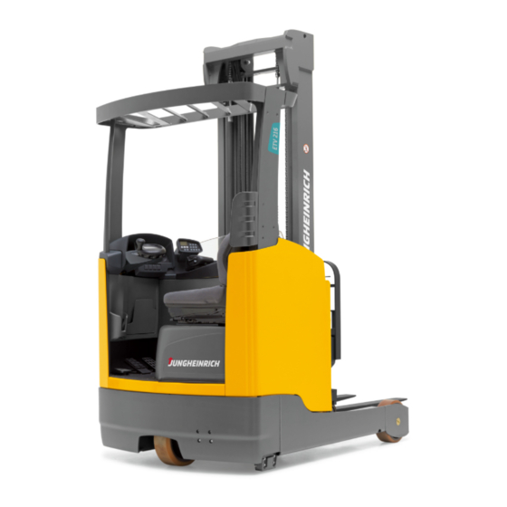
B Truck Description Application The ETM/V 214/216 is a three wheel electric side seated, clear view reach truck. It is designed for use on level floors to lift and transport goods. Open bottom pallets or palets with transverse boards can be lifted inside or outside the area of the load wheels, and trolleys can be lifted. -
Page 13: Description Of Assemblies And Their Function
Description of Assemblies and their Function 12 13 14 Item. Description Item. Description t Clear View Lift Mast t Accelerator t Overhead Guard t Battery trolley unlocking t Free Lift Cylinder t Driver’s display (not with ZT-Lifting Frame) t Multi-Pilot o On board computer t Load Wheels t Two stage switch key with... -
Page 14: Truck
Safety Instructions: An enclosed vehicle design with rounded edges facilitates safe handling of the ETM/V 214/216. The driver is protected by the driver’s cab (2). The drive wheel (7) and the load wheels (5) are protected by a solid anti-crash mechanism. - Page 15 Brake Equipment: The electric braking unit consists of three independent braking systems. Operating the brake pedal introduces regenerative braking. Where required the load wheel brakes are activated via the vehicle’s brake control system. The safety brake is electrically operated and works mechanically through a compression spring applied to a magnet brake mounted on the drive unit.
- Page 16 12 13 14 Item. Description Item. Description t Clear View Lift Mast t Accelerator t Overhead Guard t Battery trolley unlocking t Free Lift Cylinder t Driver’s display (not with ZT-Lifting Frame) t Multi-Pilot o On board computer t Load wheels t Two stage switch key with spare key (service).
-
Page 17: Placing The Load
Operating and Display Elements: Operating and display elements can be clearly identified in the driver’s cab. The Multi-Pilot (4) enables single handed operation of functions governing direction of travel, lifting / lowering, mast forward / back, mast tilt, sideshift left or right in sideshift mode (auxiliary hydraulic system HF5) (o)) and horn. -
Page 18: Technical Data Standard Design
Technical Data Standard Design Release of technical data in accordance with VDI 2198. Technical modifications and supplements reserved. Performance Data Description ETM/V 214 ETM/V 216 Q Capacity (where C = 600 mm) 1400 1600 c Load Centre of Gravity Travel Speed 14.0 / 14.0... - Page 19 β β...
-
Page 20: Standard Hoist Frames Etm/V 214/216
Standard Hoist Frames ETM/V 214/216 Description Telescopic Twin Lift Twin Lift Mast (ZT) Triplex Mast Triplex Mast (DZ) (DZ) reinforced Build Height 1950 - 2700 1950 - 3540 2700 - 3950 Free Lift 1306 - 2896 2056 - 3306 Lift... - Page 21 β β B 10...
-
Page 22: En Standards
EN Standards Constant Noise Level: 68 dB(A) In accordance with EN 12053 complies with ISO 4871. The constant noise level is calculated in accordance with standard guidelines and takes into account the noise levels when driving, lifting and idling. The noise level is measured at the driver’s ears. -
Page 23: Identification Points And Data Plates
Identification Points and Data Plates 19, 20, 21 1,5 V Item. Description Warning Sign "Caution Low Voltage Electronics " UVV Test Notice (D only ) Drive direction when turning steering wheel Capacity plate, Capacity Sideshifter Capacity plate, Capacity / Load Centre of Gravity / Fork arms Capacity plate, Capacity / Load Centre of Gravity / Lift height Sign "Put on Safety Belt"... - Page 24 Data plate, truck Item. Description Item. Description Type Manufacturer Serial no.. Battery weight min/max in kg Rated capacity in kg Drive power Battery Voltage V Load centre of gravity distance in mm Net weight without battery in kg. Year of manufacture Manufacturer’s logo Option For queries regarding the truck or ordering spare parts please quote the vehicle serial...
-
Page 25: Jack Securing Point
Capacity Plate, Capacity / Load Centre of Gravity / Lift Height The capacity plate (22) gives the capacity (Q) of the vehicle in kg with a vertical hoist frame. In tabular form the maximum capacity is shown with a standard load centre of gravity distance * C (in mm) and the desired lift height H (in mm). -
Page 26: C Transport Und Commissioning
C Transport und Commissioning Transport Depending on the height of the hoist frame and local conditions three different types of lifts may be undertaken: – Standing with assembled hoist frame (for low heights) – Standing with partially assembled hoist frame tilted against the overhead guard (for average height). -
Page 27: Lifting By Crane
Lifting by Crane Only use lifting equipment with sufficient capacity. (Weight Lifted = Net Weight + Battery Weight; see data plate, truck). – In order to lift the truck with a harness wrap slings around the strut of the overhead guard. -
Page 28: Securing The Machine For Transport
Securing the Machine for Transport. When transported on a lorry or a trailer the vehicle must be securely fastened down. The lorry or trailer must have securing rings fitted to its body. – To secure the vehicle pass the tensioning strap (3) through the overhead guard strut (1) and attach it to the securing rings. -
Page 29: Transport Lock, Safety Brake
Transport Lock, Safety Brake If a vehicle is delivered with or without a flat battery before the vehicle is started the transport locking device must be removed (2xM5 bolts). This device locks the compression spring which operates the safety brake so that the vehicle has no brakes when there is no power. -
Page 30: Commissioning
Moving the truck without a battery – Withdraw battery plug. – Push driver’s seat out of the guide towards the steering wheel. – Remove fan plug from seat hood. – Remove seat hood (see Chapter F). – Remove two-pin plug from magnetic brake –... -
Page 32: D Battery - Maintenance, Charging, Replacement
D Battery - Maintenance, Charging, Replacement Safety Regulations when handling acid batteries Before any work is carried out on the batteries the truck must be safely parked (see Chapter E). Maintenance Personnel: Batteries may only be charged, maintained or changed by staff particularly trained for that purpose. -
Page 33: Battery Types
Battery Types Depending on truck application various types of batteries may be installed. The following table shows which combinations can be included as standard: Capacitance Standard (L) High Performance HX) 48 V - 3PzS - Battery 420 Ah 420L 450H 48 V - 4PzS - Battery 560 Ah 560L... -
Page 34: Battery Troley - Emergency Unlocking
The truck must only be driven slowly inside the battery charging station with the battery leading! Battery troley - Emergency Unlocking – Preparation for Use (see Chapter E). – Tilt Multi-Pilot (1) towards arrow (U), move the mast holder up to the stop position towards the battery. -
Page 35: Battery Charging
Before installing the battery lock rectify the fault on the battery unlocking system. The safety switch for the battery lock only enables creep mode providing the battery trolley is unlatched and the control light (4) is still lit. To start up the truck the battery trolley must be in its leaving position in order to uncouple the battery trolley and the mast. -
Page 36: Removing And Fitting The Battery
Removing and Fitting the Battery. – Expose Battery (see Section 3). In order to avoid a short circuit, exposed poles or connections must be covered with an rubber cover. When using a crane to change the battery ensure that there is sufficient lifting capacity (see battery weight on the battery data plate fitted to battery holder). -
Page 37: Battery Discharge Display, Battery Discharge Monitor, Hourmeter
Battery Discharge Display, Battery Discharge Monitor, Hourmeter Driver’s Display (t) Battery Discharge Display: The charge status of the battery (10) is displayed in 10% increments on the driver’s display unit. The serial setting for the battery discharge display / discharge monitor is applied to standard batteries. - Page 38 Hourmeter: Pressing the shift key (13) briefly produces other display fields (12 and 14). If no lift height, maximum lift or load weight is available then the appropriate lines are by-passed. Display Field 1 (14) Display Field 2 (12) Operating Hours Load Weight Operating Hours Lift Height...
-
Page 39: On Board Computer (O)
On Board Computer (o) Battery Discharge Display: The charge status of the battery (15) is shown in 10% increments on the display. The serial setting of the battery discharge display / discharge monitor is applied to standard batteries. When using maintenance free batteries the display must be set so that the symbol (T) appears after the percentage figure. - Page 40 Hourmeter: The operating hours are displayed next to the clock time. The operating hours meter (17) shows the total time of travel and lifting movements. Display "Energy Recovery" when lowering and braking pay load During “Energy Recovery" the discharge display on the computer switches over so that the bars in the battery icon fill up from 0 to 100% (from bottom to top).
- Page 41 D 10...
-
Page 42: Safety Regulations For The Operation Of Fork Lift Trucks
E Operation Safety Regulations for the Operation of Fork Lift Trucks Driver Authorisation: The forklift truck may only be used by auitable persons who have been trained to drive the truck, who have proved to the owner or his representative that they can drive and handle loads and have been authorised to operate the truck by such owner or his representative. -
Page 43: Description Of Operating And Display Elements
Description of Operating and Display Elements Item. Operating or Function Display Element t Switches current on and off. key switch By removing the switch the truck cannot be switched on by unauthorised persons. o Sets the code and switches on the truck Keypad (CANCODE) t The supply current is interrupted, all... - Page 45 Item. Operating or Function Display Element t Unlocks the battery trolley Battery trolley unlocking o Avoids damage to forks or the load in the Bridging switch outrigger area. t Adjust steering column height and distance Steering column adjustment t Displays important drive and lifting Driver display parameters;...
-
Page 47: Starting The Truck
Starting the Truck Before the truck is started, operated or a load unit raised, the driver must ensure that there is no one standing in the danger area. Daily tests and procedures before commencing work – The entire truck (particularly wheels and lifting devices) to be inspected for damage. - Page 48 Adjusting the steering column – Slacken the steering column stop (16) and set the steering head (20) to the required position horizontally and vertically. Re-tighten the steering column stop. Adjusting the arm rest – Lift the arm rest (7) lock and set the arm rest (21) to the desired position (longitudinally).
-
Page 49: How To Use The Safety Belt (O)
How to use the safety belt (o) Before starting the forklift read these instructions carefully. – Put on the belt before starting the truck. – Change belt height setting according to body size. The belt will protect against serious injury. –... - Page 50 How to proceed in unusual situations (o) If there is a danger of a tipover, proceed as follows: – Press the upper body against the back of seat. – Grip the steering wheel with both hands and fix your feet firmly on the floor.
-
Page 51: Preparation For Use
Preparation for Use Pull out the main switch (2) Insert the key in the key switch and turn to the right to position "I" or: – for trucks without a key switch enter the free switch code via CANCODE (1a), or. via the on board computer. -
Page 52: Emergency Stop Device
Emergency Stop Device The truck is equipped with an emergency stop device. After switching on the main switch (2) and the ignition switch (1) or entering the Pin code there is an automatic safety prompt. Emergency Stop Display If a fault is detected on the steering or brake systems, a display will appear on the driver display panel (t) (17) or on the board computer (o) (17a) (see Section 6.2). -
Page 53: Operating The Forklift Truck
Operating the Forklift Truck Safety Rules when Driving Routes and Work Areas: The truck may only be driven on routes specifically designated for traffic. Unauthorised persons must not enter the working area. Loads must only be deposited at the designated places Travel Procedure: The driver must adjust the speed of the truck to suit local conditions. -
Page 54: Driving, Steering, Braking
Driving, Steering, Braking Emergency Stop – Press down the main switch (2). All electrical functions are switched off. The function of the main switch must not be impaired by any external objects. Driving Only drive the truck with closed and properly locked hoods. The main travel direction is the drive direction (V). - Page 55 Steering Reverse Steering (t) When travelling forward travel (drive direction) steer left into a left hand bend and right into a right hand bend. The position of the drive wheel will be shown on the driver display panel or the on board computer. Synchronous Steering (o) –...
- Page 56 Braking with the Reversing Brake: – Press the direction switch (26) during travel. The direction of travel will be reversed and the brakes applied bythe traction current controller until the truck travels in the opposite direction. This type of operation reduces energy consumption. There will be a regeneration of energy, governed by the traction current controller.
-
Page 57: Fork Adjustment
Fork Adjustment In order to securely position a load the forks should be set as far as possible apart from each other and centrally aligned with the truck. The load centre of gravity must lie between the forks. – Tilt the locating lever (27) up. –... -
Page 58: Emergency Lowering
Lifting allow anybody stand underneath a load that is being raised. – Pull Multi-Pilot (3) in direction (H). angle control lever determines the lift speed. – Operate the Multi-Pilot until the desired height is reached. When the end stop is reached (there will be a noise from the pressure relief valve) return the control lever immediately to the start position. - Page 59 Mast Holder Reach Do not reach between the mast and the battery cover. – Tilt the Multi-Pilot (3) in direction (T) to extend the mast holder and in direction (U) to retract it. The angle of the Multi-Pilot determines the reach speed. Mast Reach Damping Hydraulic damping of the mast holder reach is automatically activated above...
- Page 60 Placing, Lifting and Transporting Load Units – Set forks to the horizontal position: Press rocker switch (31), rocker (V) or (R). – Approach the load unit – Extend the mast holder. Tilt Multi-Pilot (3) in direction (T). – Lift fork prongs to correct level: Pull Multi-Pilot (3) in direction (H).
-
Page 61: Operating Attachments
Operating Attachments Integrated Sideshift The directions left and right refer to the load when viewed from the operator’s seat Moving the sideshift to the left (from driver’s view): – Set key (32) to direction (X1) Moving the sideshift to the right (from driver’s view): –... -
Page 62: Mechanical Back Up Steering (Emergency Steering Operation)
Mechanical Back Up Steering (Emergency Steering Operation) The mechanical back-up steering system is used to recover the truck in the event of an electrical failure. It must only be implemented by trained maintenance personnel who have been trained to operate the truck. –... - Page 63 When steering in the standing position the drive wheel tyre is under tension. A correcting moment can be created by releasing the Allen screw. When the truck has reached a safe position return the brake system to operational condition! The truck must not be parked with the brakes released. –...
-
Page 64: Display Items
Display Items Driver’s Display (t) The driver display unit is the user interface to the truck. It is both a display and operating unit for the operator and service engineers. Press the 4 short stroke keys (55, 56, 57, 58) to operate the driver display and the truck. - Page 65 Item. Description Warning, warning triangle (red graphic symbol), Battery is unlocked (red graphic symbol), Overtemperature (red graphic symbol) Dead man pedal not activated (yellow graphic sysmbol) Lift limit reached (yellow graphic symbol) Forks in horizontal position (green graphic symbol), Slow travel (green graphic symbol), Sideshift in central position (green graphic symbol) Service mode active (yellow graphic symbol), Service interval expired (graphic symbol flashes)
- Page 66 The four short stroke keys are used to: – regulate travel speed (slow travel switch), – apply or release the handbrake (brake switch), – change display to service mode (shift key) and – select between travel and lift mode. The display shows: –...
-
Page 67: Driver Display Lights
Driver display lights SYMBOL Forks in horizontal position (green graphic symbol), SYMBOL Sideshift central position (green graphic symbol), SYMBOL Lift limit reached (yellow graphic symbol), SYMBOL Slow travel (green graphic symbol), SYMBOL Dead man pedal not activated (yellow graphic symbol), SYMBOL Service mode active (yellow graphic symbol), SYMBOL... - Page 68 Driver Display Keys Travel speed throttled (slow travel switch), Hand brake applied or released (brake switch), Change of display to service mode (shift key) Selection of travel and lift modes Driver display warning messages 47 48 49 50 E 27...
- Page 69 Display Further Action Meaning LED 39 on Seat switch not closed INFO 02 LED 36 on No travel direction pre-selected. LED 49 flashing Battery drained main lift cut out LED 39 on Safety switch not activated INFO 07 LED 44 flashing At least one control not in the reset position at start INFO 09 LED 42 on Creep travel applied, or pre-set by locks INFO 10 LED 38 on...
-
Page 70: On Board Computer (O)
On Board Computer (o) The on board computer represents the operator’s interface to the truck. It acts as a display and control unit for the operator as well service engineers. By pressing different keys (softkeys (64)) a range of menus (65) can be selected. Menu (66) shows three conditions: Active, inactive and not available for selection (grey background). -
Page 71: Display Symbol For On Board Computer
Display Symbol for On Board Computer ESCAPE Goes to a higher level TRAVEL PROFILE 1 Creep travel TRAVEL PROFILE 2 Normal travel Acceleration, speed etc. Can be adjusted to the driver’s requirements. TRAVEL PROFILE 3 Fast travel LIFT MENU Parameters/Diagnosis/ Error logbook SERVICE MENU / PARAMETER MENU DATA FUNCTION MENU SCROLL UP... - Page 72 Display Symbols TIME 08:45 OPERATING HOURS DISPLAY 0009 h PARAMETER SELECTION Parameters: acceleration, rollout brake, reverse brake, travel direction speed and fork direction speed. PARAMETER SELECTION Lift speed parameters STEERING ANGLE DISPLAY 360° km/h STEERING ANGLE DISPLAY 180° km/h TABULATOR To next input field WARNING SYMBOL Battery not interlocked!
-
Page 73: Operator Keypad (Cancode) (O)
Operator Keypad (CANCODE) (o) The keypad consists of 10 digit keys, one set key and one extra key o The o key indicates the operational status via a red/ green LED. It has the following functions: – Code key function (starting the truck). Code Key After entering the correct code the truck is ready for use. -
Page 74: Parameters
Starting After switching on the main switch and if necessary the key switch LED (66) shows red. On entering the correct operating code LED (65) shows green. If the wrong code is entered LED (65) flashes red for two seconds. Then the correct code can be entered. -
Page 75: Parameter Settings
Parameter Settings The master code must be entered to change the truck setting. The factory setting for the master code is 7-2-9-5. Change the master code when starting the truck for the first time (see Section 7.1). Entering the master code: –... - Page 76 The following parameters may be entered. Code Key Parameter List Function Setting Range Standard Comments Setting Workflow Code Key 000 Changes the Master Code 0000 - 9999 7295 (LED 67 flashes) Input of The length (4-6 digits) of current code the master code also pre- 00000 - 99999 determines the length of...
- Page 77 Function Setting Range Standard Comments Setting Workflow Code Key 002 Change operator code 0000 - 9999 (LED 67 flashes) Input of current code 00000 - 99999 confirm (Set) 000000 - 999999 (LED 68 flashes) Input of new code confirm (Set) (LED 69 flashes) Repeat Input of Code...
-
Page 78: Changing Truck Parameters
Keypad Fault Messages The following faults are shown by the LED (65) flashing red: – New master code is already the operator code – New operator code is already the master code – There is no operator code to be altered. –... -
Page 79: Troubleshooting
Troubleshooting All faults or consequences of incorrect operation are shown on the driver display unit. Follow the instructions shown on the display. It may be necessary to start again. Turn the main switch off and on again. If the truck will not start consider the following: Fault Possible Causes Action... -
Page 80: Auxiliary Electrical System
Auxiliary Electrical System 10.1 Headlights Item. Description o Searchlight o Searchlight o Headlight switch ON / OFF for (Item 71) o Headlight switch ON / OFF for (Item 72) The headlight is equipped with a 360° swivel link. 10.2 Beacon Item. - Page 81 10.3 Bridging Switch (ESA / electrical lift limit switch ) Item. Description o Bridging switch o Sideshift in central position symbol display Bridging switch ESA 1 ESA stands for End-Schalter-Anlage / 1 (Lift Switching System) The function of the ESA 1 is to prevent damage to the truck and/or the load by the outriggers due to incorrect operation.
-
Page 82: Bridging Switch (Esa / Electrical Lift Limit Switch )
(forward / reverse) are inhibited if the mast is not extended. On the ETM/V 214/216 the facility to lower the load in this range is cut out. Bridging switch The bridging switch (15) is locateed above the steering head and releases all functions when activated. - Page 83 E 42...
-
Page 84: F Maintenance Of Materials Handling Equipment
F Maintenance of Materials Handling Equipment Operational Safety and Environmental Protection Test and maintenance work must be carried out within the intervals specified in the maintenance check list. Any changes to the materials handling truck are forbidden especially where they affect safety mechanisms. - Page 85 Working on Electrical Equipment: Any work on electrical equipment should only be undertaken by qualified electricians. Before starting work they must take all precautions necessary to prevent electrical accidents. Battery operated trucks should be made safe by removing the battery and thereby isolating the power. Welding: In order to avoid damage to electrical and electronic components these must be removed from the truck before any welding work is carried out.
-
Page 86: Maintenance And Inspection
Maintenance and Inspection Thorough and correct maintenance is an important pre-requisite for safe operation of the truck. If regular maintenance is neglected truck breakdowns can occur which in turn could endanger life and limb and lead to operational failure. Maintenance intervals are based on single shifts, working under normal conditions. For more arduous conditions such as a dusty environment, extreme temperatures or multi-shift working patterns, maintenance intervals should be reduced accordingly. -
Page 87: Maintenance Check List Etm/V 214/216
Maintenance Check List ETM/V 214/216 Maintenance Interval Standard = t W M M M = k 1 Freezer 6 12 Frame/ Check all load bearing items for damage. Assembly: Check screw connections Check overhead guard for damage and attachment Check fixing screws in driver’s cab. - Page 88 Maintenance Interval t W M M M Standard = = k 1 Cold 6 12 Storage Electrical. Check operation System: Check cable for connections and damage. Check that fuses are of the correct rating Check operation and safety of switch Check operation of warning devices and safety switches Check switch contacts for wear, replace worn parts where necessary.
-
Page 89: Lubrication Schedule Etm/V 214/216
Lubrication Schedule ETM/V 214/216 75 ±5 Nm Min. = 13l 3,9 l Max.= 30l 195 ±10 Nm 367 ±10 Nm Contact Surfaces Grease Nipples Hydraulic Oil filler neck Hydraulic Bleed Screw Transmission Oil drain plug Drain Plug for Gearbox Oil... -
Page 90: Operating Fluids
° C at 25 °C temperature °C Saponification Lithium 265 - 295 -35 / +120 310 - 340 -52 / +100 Tank Capacity ETM/V 214/216 Litre Lift Height (h approx. up to 10250 approx. up to 9620 approx. up to 9020 approx. -
Page 91: Maintenance
Maintenance Prepare truck for maintenance and repairs All necessary safety measures must be implemented to avoid accidents during repair and maintenance work. Park truck safely (see Chapter E). – Remove battery plug (1). – This ensures that the truck cannot be accidentally put into operation. When working under raised forks or a raised truck ensure that the truck cannot lower, tip over or slide. -
Page 92: Removing The Seat Hood
Removing the seat hood – Pull seat locking lever (2) up and push seat (3) towards the steering wheel. – Disconnect fan connection – Slacken fixing screws (4) remove hood (5). Expose drive unit and hydraulic equipment for maintenance. Checking the hydraulic oil level –... -
Page 93: Opening The Fuse Cover
Opening the fuse cover – Exerting a little force, withdraw hood and set to one side. The fuses are located under the hood. Removing cover from instrument panel – Slacken the screws in the safety screen. Push the steering wheel towards the seat (furthest position). -
Page 94: Checking The Electrical Fuses
Checking the electrical fuses. – Prepare truck for maintenance and repairs (see Section 6.5 and 6.6). – Ensure all the fuses are of the correct rating (see table) and replace if necessary. Item Description Rating / Type 4F11 Driver Display / On Board Computer Fuse Radio fuse 1 F 4 Steering Electronics / Travel Control Fuse... -
Page 95: Starting The Truck Again
Starting the Truck Again After cleaning and maintenance work, start up the truck again provided the following activities have been carried out: – Test horn. – Test main switch. – Test brakes. – Lubricate truck as per Lubrication Schedule. Putting the Truck Out of Service If, for operational reasons, the truck is out of service for longer than two months it must be parked in a frost free, dry area and measures before, during and after decommissioning must be carried out as described. -
Page 96: Starting The Truck Again After De-Commissioning
Starting the truck again after de-commissioning – Thoroughly clean the truck. – Lubricate truck as per Lubrication Schedule (see Chapter F). – Clean battery, grease terminal scews with dielectric grease and connect battery. – Charge up the battery (see Chapter D). –... - Page 97 F 14...
Need help?
Do you have a question about the ETM/V 214 and is the answer not in the manual?
Questions and answers