Table of Contents
Advertisement
Advertisement
Chapters
Table of Contents

Related Manuals for Jungheinrich ERE 224


Summary of Contents for Jungheinrich ERE 224
- Page 1 ERE 224 09.05- Operating instructions 50468220 01.06...
- Page 2 Used to indicate standard equipment. Used to indicate optional equipment. Our trucks are subject to ongoing development. Jungheinrich reserves the right to alter the design, equipment and technical features of the truck. No guarantee of particular features of the truck should therefore be inferred from the present operating instructions.
-
Page 4: Table Of Contents
Table of contents Correct use and application of the truck Truck description Application ................... B 1 Assemblies ..................B 2 Technical data ..................B 3 Performance data ................B 3 Dimensions ..................B 4 EN standards ..................B 5 Conditions for application ..............B 5 Location of instruction labels and identification plates ...... - Page 5 Operation Safety regulations governing the operation of the fork-lift truck ..E 1 Description of the operating controls and displays ......E 2 Starting up the truck ................E 6 Truck variants ..................E 6 Switching on the truck ................. E 6 Operation of the fork-lift truck ..............
- Page 6 Maintenance of the fork-lift truck Operational safety and environmental protection ........ F 1 Safety regulations applicable to truck maintenance ......F 1 Servicing and inspection ..............F 3 Maintenance checklist ................ F 4 Lubrication schedule ................F 6 Consumption-type materials ............... F 7 Description of the servicing and maintenance operations ....
- Page 8 Appendix JH Traction Battery Operating Instructions These operating instructions apply only to Jungheinrich battery models. If using another brand, refer to the manufacturer's operating instructions.
-
Page 10: A Correct Use And Application Of The Truck
A Correct use and application of the truck The “Guidelines for the Correct Use and Application of Industrial Trucks” (VDMA) are included in the scope of delivery for this truck. The guidelines are part of these oper- ating instructions and must always be heeded. National regulations are fully applica- ble. -
Page 12: B Truck Description
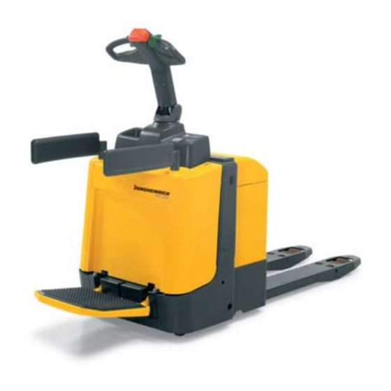
B Truck description Application The truck is an electric control shaft lift truck with hinged driver's platform and safety frames. A fixed driver standing platform is available as an option. The truck has been designed for lifting operations and transportation on level ground and is able to pick up, outside the load-bearing wheel range, pallets with open bases or lateral boards, as well as trolleys. -
Page 13: Assemblies
Assemblies Item Designation Item Designation t Controller t Hinged driver standing platform t Control shaft t Collision guard o Display instrument t Safety extension (CANDIS) t Key switch t Master switch o Keyboard o Fixed driver standing platform (CANCODE) t Supporting wheel o Deadman key t Driven wheel = Standard equipment... -
Page 14: Technical Data
Technical data Indication of technical data according to VDI 2198. Subject to modification and supplements. Performance data Designation Capacity 2.400 kg Load centre distance 600 mm Travelling speed, pedestrian-controlled operation 4,5 km/h with/without load Travelling speed, stand-on operating mode 8,5 / 10 km/h with/without load Lift speed with/without load 0,04 / 0,05 m/s... -
Page 15: Dimensions
Dimensions (all dimensions in mm) Designation Height of fork when lowered Lift Distance between forks, outside 510 / 540 / 670 Distance between forks, inside 170 / 200 / 330 Fork width Track width 340 / 370 / 500 Safety distance Dead weight: Refer to truck identification label Length including fork back I... -
Page 16: En Standards
EN standards Continuous sound level: 68 dB(A) according to EN 12053 as stipulated in ISO 4871 The continuous sound level is a value averaged according to standard regulations, taking the sound pressure level into account when driving, lifting and idling. The sound pressure level is measured at the ear. -
Page 17: Location Of Instruction Labels And Identification Plates
Location of instruction labels and identification plates Item Designation Truck identification plate Caution: Heed the operating instructions! (see chapter C) Rated capacity Attachment point of hooks for transportation by crane Battery identification plate Accident prevention inspection label The truck identification plate (14) is visible after the front hood has been opened (refer to chapter F). - Page 18 Truck identification plate Item Designation Item Designation Type Manufacturer logo Serial No. Min./max. battery weight in kg Rated capacity in kg Drive power in kW Battery voltage Load centre distance in mm Empty weight without battery in kg Year of manufacture Manufacturer Option In the event of queries relating to the truck or spare part orders, please give the serial...
-
Page 20: C Transportation And Commissioning
C Transportation and commissioning Transportation by crane Only lifting gear of adequate capacity must be used (for the weight of the truck, refer to the truck identification plate - see chapter B). Attachment points (1) are provided on the chassis and the fork for transport- ing the truck with lifting gear. -
Page 21: Commissioning
Commissioning The truck must only be operated on battery current! Rectified alternate current will damage the electronic components. Cables connected to the battery (trailing cables) must be less than 6 meters in length. For trucks starting from February 2001, transport plugs have been introduced. When there is no battery in the truck, the truck cannot be braked with counter-current brake and service brake. -
Page 22: Moving The Truck With The Drive Unit Inoperative
In order to prepare the truck for work following delivery or transportation, the following operations must be performed: – Check the truck for completeness and satisfactory condition of the equipment. – If necessary, install the battery. Do not damage the battery cable. –... -
Page 24: D Battery - Servicing, Recharging, Replacement
D Battery - Servicing, recharging, replace- ment Safety regulations governing the handling of lead-acid batteries The truck must be parked and rendered safe before any operations on batteries are undertaken (refer to chapter E). Servicing staff: Recharging, servicing and replacing of batteries must only be per- formed by qualified personnel. -
Page 25: Battery Types
Battery types The battery types meet the EN 60254-2 standards. The following table shows the battery combinations and battery capacities: Battery type Battery compartment ap- Battery compartment ap- prox. 225 mm prox. 295 mm 24 V batteries 3 EPzB 300 Ah 3 EPzS 345 Ah 24 V batteries (performance-enhanced) -
Page 26: Battery Removal From The Side (O)
Battery removal from the side (o) – Set the master switch (7) to position “OFF”. – Unlock the hood locking mechanism (4) by pressing it down, tilt the battery hood (5) towards the front and unlock the hood catch (6) –... -
Page 27: Charging The Battery
Charging the battery – Park the truck and render it safe (refer to chapter E). Do not connect or disconnect the battery connector and the socket unless the truck is switched off. – Expose the battery (refer to section 3). During the recharging operation, the tops of the battery cells must be exposed to en- sure adequate ventilation. -
Page 28: Removing And Installing The Battery
Removing and installing the battery The truck must be parked on level ground. To prevent short-circuits, batteries with ex- posed poles or cell connectors must be covered using rubber matting. Place the bat- tery connector or the battery cable, respectively, in such a way that they will not catch behind any truck protrusions when the battery is withdrawn. -
Page 29: Removal "Battery Removal From The Side" (O)
Removal “Battery removal from the side” (o) – Expose the battery (refer to section 3). – Push the battery against the chassis in order to relieve the battery support (13). – Lift the battery support , push it a short distance into the chassis , lift and with- draw it... -
Page 30: Safety Regulations Governing The Operation Of The Fork-Lift Truck
E Operation Safety regulations governing the operation of the fork-lift truck Driving permission: The fork-lift truck must only be operated by persons who have been trained in the operation of trucks, who have demonstrated to the user or his rep- resentative their capability of moving and handling loads, and who have expressly been charged by the user or his representative with the operation of the truck. -
Page 31: Description Of The Operating Controls And Displays
Description of the operating controls and displays Item Operating control or display Function t Pedestrian-controlled operation: Hinged standing platform – Driver standing platform in folded-up position: Truck travelling speed is limited to 4.5 km/h. Stand-on operating mode, standing platform serves as the deadman switch: –... - Page 33 Item Operating control or display Function t Issues a warning signal. Operating key - Horn t Lowers the fork. Operating key “Lowering” t Lifts the fork. Operating key “Lifting” o Emergency stop and service brake Brake switch (variant “Suspended standing platform”) o Steering Control shaft...
-
Page 35: Starting Up The Truck
Starting up the truck The driver must make sure that nobody is within the danger area of the truck before the truck is switched on or operated, or before a load is lifted. Checks and operations to be performed before starting daily work –... -
Page 36: Operation Of The Fork-Lift Truck
Operation of the fork-lift truck Safety regulations applicable when operating the truck Driving lanes and work areas: Only such lanes and routes that are specially allo- cated for truck traffic must be used. Unauthorised persons must stay away from work areas. -
Page 37: Driving, Steering, Braking
Driving, steering, braking Be extremely careful when driving and steering, especially when parts of the body protrude from the truck contour. Make sure to keep sufficient distance when the truck is operated with an accompany- ing person. The electric steering system is self-monitoring. The steering control systems monitors the fault frequency over a certain period. - Page 39 Driving Truck with hinged standing platform and movable control shaft: There are two different travelling modes: When swivelling the standing platform upwards, do not reach between the standing platform and the truck’s side wall. – Pedestrian-controlled operation: Starting with safety extension (2.2), swivel the safety extensions (2.1 and 2.2) inwards and then fold up the standing platform (1).
- Page 40 E 11...
- Page 41 Steering In narrow bends, the driver will be positioned at the outer contours of the truck. – Swivel the control shaft (9, 14) to the left or right. Braking The braking behaviour of the truck strongly depends on the state of the floor. This must be taken into account by the driver for his driving behaviour.
- Page 42 E 13...
-
Page 43: Picking Up And Setting Down Loads
Picking up and setting down loads Before picking up a load, the driver has to check that the load rests properly on its pallet and that it does not exceed the capacity of his truck. – Pass the fork tines as far as possible under the load. -
Page 44: Safe Parking Of The Truck
Safe parking of the truck When the truck is parked and left unat- tended, it must be rendered safe even if it is left unattended for only a short peri- od of time. – Never park the truck on a slope or in- cline. -
Page 45: Keyboard (Cancode) (O)
Keyboard (CANCODE) (o) The operator keyboard is composed of 10 nu- meric keys, a Set key and an o-key. The green LED in key 1 indicates that the drive programme was switched on with key 1. The o-key indicates operating conditions by a red/green LED. - Page 46 Commissioning After switching on the master switch and, if required, the key switch, the LED (20) lights up red. After entering the correct operator code (factory setting 2-5-8-0) the LED (20) lights up red. When an incorrect code has been entered, LED (20) lights up red for two seconds. After that you can enter a new code.
-
Page 47: Drive Programme
Drive programme The truck features one drive programme. The green LED (22) indicates the active programme, buttons 2 and 3 have no function. The drive programme can be individually adapted to match the truck application. Parameters In the programming mode, the operating keyboard allows code lock and drive pro- gramme to be adapted. -
Page 48: Parameter Settings
Parameter settings To change the truck settings the master code must be entered. The master code is factory-set to 7-2-9-5. Change the master code when setting the truck into operation for the first time (refer to section 5.1). Safety notes for trucks with indicator instrument (CANDIS (o)) –... - Page 49 Setting procedure for trucks with and without indicator instrument (CANDIS (o)): – Enter the three-digit parameter number and confirm with Set key (21). – The indicator instrument (CANDIS (o)) continues to display the operating hours. If the display changes, cancel the setting procedure with the o-key (25) and restart from the beginning.
- Page 50 Function Range Default Comments Setting value Setting Work flow value Code lock 002 Change operator code 0000 - 9999 (LED 22 flashes) Enter the current code 00000 - 99999 Confirm (Set) 000000 - 999999 (LED 23 flashes) Enter a new code Confirm (Set) (LED 24 flashes) Repeat the code en-...
- Page 51 Function Range Default Comments Setting value Setting val- Work flow Code lock 030 Display of the number of used operator codes* only in conjunction with indicator instrument (CANDIS (o)) Keyboard error messages The following errors are indicated by a red flashing LED (20): –...
-
Page 52: Travel Parameters
Travel parameters For trucks without indicator instrument (CANDIS (o)) the code lock parameters can only be set by the manufacturer's service. The following example shows the parameter setting for the acceleration of travel pro- gram 1 (parameter 101). Acceleration example Display instrument LED (20) LED (22) - Page 53 The following parameters can be entered: Drive programme Function Range Standard Comments Setting value Setting value 101 Acceleration 0 - 9 102 Coasting brake 0 - 9 104 Maximum speed in drive 0 - 9 depending on direction via controller controller 105 Pedestrian-controlled op- 0 - 9...
-
Page 54: Display Instrument (Candis) (O)
Display instrument (CANDIS) (o) The instrument indicates: – Remaining battery charge (LED bars (27)), – Operating hours (LC display (29)). In addition, error messages of the electronic components and parame- ter changes are displayed. Discharge status indication Depending on the battery type set, switch-on limits for the additional “Warning” (26) and “Stop”... -
Page 55: Discharge Monitor Function
Discharge monitor function With the discharge monitor function enabled, the lifting function switches of when reaching the discharge limit (the Stop LED switches on). Travelling and lowering is still possible. For wet batteries the residual capacity is 20%, for maintenance-free bat- teries it is 40%. -
Page 56: Fault Location
Fault location This chapter enables the user to locate and to remedy simple faults or the conse- quences of operating errors. Fault locating operations should be performed in the or- der as set out in the table below. Fault Possible cause Remedy Truck –... -
Page 58: F Maintenance Of The Fork-Lift Truck
F Maintenance of the fork-lift truck Operational safety and environmental protection The checks and servicing operations contained in this chapter must be performed in accordance with the intervals as indicated in the servicing checklists. Modifications of fork-lift truck assemblies, especially of the safety installations, are not permitted. - Page 59 Work on the electric system: Work on the electric system of the truck must only be performed by personnel specially trained for such operations. Before commencing any work on the electric system, all measures required to prevent electric shocks have to be taken. For battery-operated fork-lift trucks, the truck must also be depow- ered by removing the battery plug.
-
Page 60: Servicing And Inspection
Servicing and inspection Thorough and expert servicing is one of the most important preconditions for safe op- eration of the fork-lift truck. The neglect of regular servicing intervals can lead to fork- lift truck failure and constitutes a potential hazard to personnel and equipment. The indicated servicing intervals are based on single-shift operation under normal op- erating conditions. -
Page 61: Maintenance Checklist
Maintenance checklist Maintenance intervals = t W A B C Standard Cold store = k Chassis/ 1.1 Check all load bearing elements for damage super- 1.2 Check all bolted connections structure: 1.3 Check platform for correct functioning and damage Drive unit: 2.1 Check the transmission for noises and leakage 2.2 Checking the transmission oil level 2.3 Change the transmission oil... - Page 62 Maintenance intervals = t W A B C Standard Cold store = k Battery: 9.1 Check acid density, acid level and cell voltage 9.2 Check the terminals for secure attachment and apply grease 9.3 Clean the battery connections; check for tight fitting 9.4 Check the battery cables for damage, renew if necessary Lifting 10.1 Check performance, wear and adjustment...
-
Page 63: Lubrication Schedule
Lubrication schedule 1,25l - 1,3l 0,7l g Slide surfaces 1) Compound for cold store usage 1:1 Grease nipple Filler plug for hydraulic oil 2) 1.25 l - 1.3 l depending on the transmission variant b Filler plug for transmission oil (level must always reach the lower edge a Drain plug for transmission oil of the filler neck) -
Page 64: Consumption-Type Materials
Consumption-type materials Handling consumption-type materials: Consumption-type materials must always be handled properly. Manufacturer's instructions are to be observed. Improper handling is injurious to health, life, and environment. Consumption-type ma- terials must be stored in adequate containers. They might be inflammable and, there- fore, must not come into contact with hot components or open fire. -
Page 65: Description Of The Servicing And Maintenance Operations
Description of the servicing and maintenance operations Preparing the truck for the performance of the servicing and maintenance op- erations All required safety measures must be taken to prevent any accidents in the course of the servicing and maintenance operations. The following preparatory operations must be performed: –... -
Page 66: Checking The Mounting And The Attachment Of The Drive Wheel
Checking the mounting and the attachment of the drive wheel – Prepare the truck for the performance of servicing and maintenance opera- tions (refer to section 6.1). – Open the front hood (refer to section 6.2). – Separate the control lead connections to the standing platform (6). -
Page 67: Checking The Electric Fuses
Checking the electric fuses – Prepare the truck for the performance of servicing and maintenance operations (re- fer to section 6.1). – Open the front hood (refer to section 6.3). – Refer to the table and check all fuses for correct rating. Replace if required. Item Designation Protection of: Value... -
Page 68: Recommissioning The Truck
Recommissioning the truck Recommissioning of the truck following the performance of cleaning or maintenance work is permitted only after the following operations have been performed: – Check the horn for proper functioning. – Check the master switch for correct functioning. –... -
Page 69: Recommissioning The Truck
Recommissioning the truck – Thoroughly clean the fork-lift truck. – Lubricate the fork-lift truck according to the lubrication chart (refer to chapter F). – Clean the battery. Grease the pole screws using pole grease and reconnect the battery. – Recharge the battery (refer to chapter D). –... - Page 70 Jungheinrich traction battery Table of contents Jungheinrich traction battery ..........2-6 with positive tubular plates type EPzS and EPzB Type plate Jungheinrich traction battery..........7 Instruction for use ............8-12 Aquamatic/BFS III water refilling system Jungheinrich traction battery Maintenance free traction batteries with positive tubular plates type EPzV ....................13-17...
-
Page 71: Jungheinrich Traction Battery
Jungheinrich traction battery with positive tubular plates type EPzS and EPzB Rating Data 1. Nominal capacity C5: See type plate 2. Nominal voltage: 2,0 V x No of cells 3. Discharge current:: C5/5h 4. Nominal S.G. of electrolyte* Type EPzS:... - Page 72 Ignoring the operation instructions, repair with non-original parts or using additives for the electrolyte will render the warranty void. For batteries in classes I and II the instructions for maintaining the appropriate protection class during operation must be complied with (see relevant certificate). 1.
- Page 73 Battery container lids and the covers of battery compartments must be opened or re- moved. The vent plugs should stay on the cells and remain closed. With the charger switched off connect up the battery, ensuring that the polarity is cor- rect.
- Page 74 3. Maintenance 3.1 Daily Charge the battery after every discharge. Towards the end of charge the electrolyte level should be checked and if necessary topped up to the specified level with purified water. The electrolyte level must not fall below the anti-surge baffle or the top of the separator or the electrolyte „min“...
- Page 75 5. Storage If batteries are taken out of service for a lengthy period they should be stored in the fully charged condition in a dry, frost-free room. To ensure the battery is always ready for use a choice of charging methods can be made: 1.
-
Page 76: 7. Type Plate, Jungheinrich Traction Battery
7. Type plate, Jungheinrich traction battery Baujahr T ype Year of manufacture Serien-Nr. Lieferanten Nr. Serial-Nr. Supplier No. Nennspannung Kapazität Nominal V oltage Capacity Zellenzahl Batteriegewicht min/max Number of Cells Battery mass min/max Hersteller Jungheinrich AG, D-22047 Hamburg, Germany Manufacturer... -
Page 77: Aquamatic/Bfs Iii Water Refilling System
Aquamatic/BFS III water refilling system for Jungheinrich traction battery with EPzS and EPzB cells with tubular positive plates Aquamatic plug arrangement for the Operating Instructions Cell series* Aquamatic plug type (length) EPzS EPzB Frötek (yellow) (black) 2/120 – 10/ 600 2/ 42 –... - Page 78 Diagrammatic view Equipment for the water refilling system 1. Water tank 2. Level switch 3. Discharge point with ball valve 4. Discharge point with sole- noid valve 5. Charger 6. Sealing coupler 7. Closing nipple 8. Ion exchange cartridge with conductance meter and solenoid valve 9.
- Page 79 4. Filling (manual/automatic) The batteries should be filled with battery water as soon as possible before the battery charging comes to an end; this ensures that the refilled water quantity is mixed with the electrolyte. In normal operation it is usually sufficient to fill once a week. 5.
- Page 80 8. Battery hose connections Hose connections for the individual plugs are laid along the existing electric circuit. No changes may be made. 9. Operating temperature The temperature limit for battery operation is set at 55° C. Exceeding this temperature damages the batteries. The battery filling systems may be operated within a tempe- rature range of >...
- Page 81 10.2.1 Clamping ring tool The clamping ring tool is used to push on a clamping ring to increase the contact pres- sure of the hose connection on the plugs' hose couplings and to loosen it again. 10.3 Filter element For safety reasons a filter element (ident no.: 50307282) can be fitted into the batte- ry's main supply pipe for supplying battery water.
-
Page 82: Jungheinrich Traction Battery
Jungheinrich traction batterie Maintenance free Jungheinrich traction batterie with positive tubular plates type EPzV and EPzV-BS Rating Data 1. Nominal capacity C5: See type plate 2. Nominal voltage: 2,0 Volt x No of cells 3. Discharge current: C5/5h 4. Rated temperature: 30°... - Page 83 Ignoring the operation instructions, repair with non-original parts and non authorised interventions will render the warranty void. For batteries in classes I and II the instructions for maintaining the appropriate protection class during operation must be complied with (see relevant certificate). 1.
- Page 84 With the charger switched off connect up the battery, ensuring that the polarity is cor- rect (positive to positive, negative to negative). Now switch on the charger. When charging the temperature of the battery rises by about 15° C, so charging should only begin if the battery temperature is below 35°...
- Page 85 3.2 Weekly Visual inspection after recharging for signs of dirt and mechanical damage. 3.3 Quarterly After the end of the charge and a rest time of 5 h following should be measured and recorded: • the voltages of the battery •...
-
Page 86: 7. Type Plate, Jungheinrich Traction Battery
Batteries with this sign must be recycled. Batteries which are not returned for the recycling process must be disposed of as hazardous waste! We reserve the right make technical modification. 7. Type plate, Jungheinrich traction battery Baujahr T ype Year of manufacture Serien-Nr.
Need help?
Do you have a question about the ERE 224 and is the answer not in the manual?
Questions and answers