
Subscribe to Our Youtube Channel
Related Manuals for Jungheinrich ETV 110


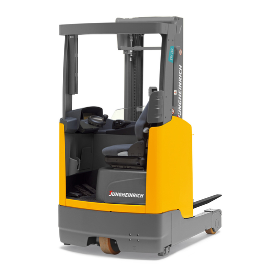
Summary of Contents for Jungheinrich ETV 110
- Page 1 ETV 110-116 ETV 110-116 12.05 - 12.05 - Operating Instructions Operating Instructions 50468482 50468482 ETV 110 ETV 110 07.12 07.12 ETV 112 ETV 112 ETV 114 ETV 114 ETV 116 ETV 116 https://www.besttruckmanuals.com/...
- Page 2 Declaration of Conformity Declaration of Conformity Jungheinrich AG, Am Stadtrand 35, D-22047 Hamburg Jungheinrich AG, Am Stadtrand 35, D-22047 Hamburg Manufacturer or authorized representative in the Community Manufacturer or authorized representative in the Community T T y y p p e e O O p p t t i i o o n n S S e e r r i i a a l l N N o o .
- Page 3 B B G G . . 9 9 0 0 0 0 1 1 2 2 https://www.besttruckmanuals.com/...
- Page 4 Important notes on transporting and mounting load lifting devices Important notes on transporting and mounting load lifting devices to reach trucks to reach trucks Transport Transport Depending on the overall height of the lifting mast and the local conditions transport Depending on the overall height of the lifting mast and the local conditions transport can be performed in three different ways can be performed in three different ways...
- Page 5 B B G G . . 3 3 0 0 9 9 0 0 2 2 https://www.besttruckmanuals.com/...
- Page 6 Used to indicate optional equipment. Used to indicate optional equipment. Our trucks are subject to ongoing development. Jungheinrich reserves the right to Our trucks are subject to ongoing development. Jungheinrich reserves the right to alter the design, equipment and technical features of the truck. No guarantee of ...
- Page 7 B B G G . . 8 8 0 0 1 1 0 0 https://www.besttruckmanuals.com/...
- Page 8 Index Index A A Correct Use and Ap Correct Use and Application plication Gener General al ......................................A A 1 1 Correc Correct t applic application ation ..
- Page 9 Batter tery y Ma Maint intena enance nce, , Cha Chargi rging ng & & Rep Replac laceme ement nt Safety Safety regula regulations tions for for handli handling ng acid acid batter batteries ..ies ........
- Page 10 ............................F F 6 6 ETV 110-11 110-116 6 mainte maintenance nance checkl checklist ist ...................... F F 7 7...
- Page 11 B B G G . . 9 9 0 0 0 0 1 1 https://www.besttruckmanuals.com/...
- Page 12 JH Traction Battery JH Traction Battery Operating Instructions Operating Instructions These operating instructions apply only to Jungheinrich battery models. If using These operating instructions apply only to Jungheinrich battery models. If using another brand, refer to the manufacturer's operating instructions.
- Page 13 B B G G . . 6 6 0 0 5 5 0 0 https://www.besttruckmanuals.com/...
- Page 14 2 2 A A Correct Use a Correct Use and Applica nd Application tion G G e e n n e e r r a a l l The industrial truck described in the present operating instructions is designed for The industrial truck described in the present operating instructions is designed for ...
- Page 15 A 1 A 1 P P r r o o p p r r i i e e t t o o r r r r e e s s p p o o n n s s i i b b i i l l i i t t i i e e s s For the purposes of the present operating instructions the “proprietor”...
- Page 16 A A p p p p l l i i c c a a t t i i o o n n The ETV 110-116 is a three wheel electric side seat, clear view reach truck. It is The ETV 110-116 is a three wheel electric side seat, clear view reach truck. It is designed for use on level floors to lift and transport goods.
- Page 17 A A s s s s e e m m b b l l i i e e s a s an n d F d Fu u n n c c t t i i o o n n a a l D l De e s s c c r r i i p p t t i i o o n n I I t t e e m m D D e e s s c c r r i i p p t t i i o o n n...
- Page 18 An enclosed truck geometry with rounded edges facilitates safe handling of the ETV 110-116. The driver is safe handling of the ETV 110-116. The driver is protected by the overhead guard (2). protected by the overhead guard (2). The drive wheel (7) and the load wheels (5) are protected by a solid ram protection.
- Page 19 Brake system: Brake system: The electric brake system consists of independent brake systems. The electric brake system consists of independent brake systems. Applying the brake pedal results i Applying the brake pedal results in inversion braking (plugging) in the traction n inversion braking (plugging) in the traction motor.
- Page 20 I I t t e e m m D D e e s s c c r r i i p p t t i i o o n n I I t t e e m m D D e e s s c c r r i i p p t t i i o o n n ...
- Page 21 The mast support rails for the ETV 114/116 are screwed onto 114/116 are screwed onto the outriggers (6). For the outriggers (6). For the ETV 110/112 the rails the ETV 110/112 the rails are housed within the outriggers (6).
- Page 22 3 3 . . 1 1 P P e e r r f f o o r r m m a a n n c c e e d d a a t t a a ETV 110/112 ETV 110/112...
- Page 23 1 1 ETV 114/116 ETV 114/116 D D e e s s c c r r i i p p t t i i o o n n E E T T V V 1 1 1 1 4 4 E E T T V V 1 1 1 1 6 6 Q Q C C a a p p a a c c i i t t y y ( ( w w h h e e r r e e C C = = 6 6 0 0 0 0 m m m m ) ) 1 1 4 4 0 0 0 0...
- Page 24 (all distances in mm) (all distances in mm) ETV 110/112 (280Ah) ETV 110/112 (280Ah) DZ-GE DZ-GE D D e e s s c c r r i i p p t t i i o o n n E E T T V V 1 1 1 1 0 0...
- Page 25 0 0 1 1 β β α α β β α α b b b b a a W W st st B B https://www.besttruckmanuals.com/ G G .
- Page 26 Axle loading forks back w. load front/rear load front/rear a)Applies to ETV a)Applies to ETV 110/112 with 280 Ah battery 110/112 with 280 Ah battery and ETV 114/116 with and ETV 114/116 with 420 Ah battery. 420 Ah battery. Other...
- Page 27 0 0 0 0 1 1 B 11 B 11 3 3 . . 6 6 B B a a t t t t e e r r y y See battery types in chapter D. See battery types in chapter D. 3 3 .
- Page 28 0 0 0 0 1 1 B 12 B 12 3 3 . . 8 8 M M a a s s t t w w e e i i g g h h t t s s The weight of the mast can be calculated using the formulae given below.
- Page 29 9 9 0 0 0 0 1 1 B 13 B 13 β β α α β β α α b b b b a a W W st st...
- Page 30 9 9 0 0 0 0 1 1 B 14 B 14 3 3 . . 9 9 E E N N n n o o r r m m s s N N o o i i s s e e e e m m i i s s s s i i o o n n : : 6 6 8 8 d d B B ( ( A A ) ) in accorda in accordance with EN...
- Page 31 . . 9 9 0 0 0 0 1 1 B 15 B 15 3. 3.11 El Elec ectr tric ical al re requ quir irem emen ents ts The manufacturer certifies compliance with the requirements for the design and The manufacturer certifies compliance with the requirements for the design and manufacture of electrical equipment, according to EN 1175 "Industrial Truck Safety - manufacture of electrical equipment, according to EN 1175 "Industrial Truck Safety -...
- Page 32 G G . . 9 9 0 0 0 0 1 1 B 16 B 16 I I d d e e n n t t i i f f i i c c a a t t i i o o n p n po o i i n n t t s a s an n d d d da a t t a p...
- Page 33 G G 3 3 1 1 T T r r u u c c k k n n a a m m e e . . 9 9 0 0 0 0 1 1 B 17 B 17 4 4 .
- Page 34 G G . . 9 9 0 0 0 0 1 1 B 18 B 18 4 4 . . 2 2 T T r r u u c c k l k lo o a a d c d cha har r t ( t (c c a a p p a a c c i i t t y y ) ) Loss of stability can cause accidents...
- Page 35 B B G G . . 9 9 0 0 0 0 1 1 B 19 B 19 4 4 . . 4 4 S S t t a a b b i i l l i i t t y y The truck's stability has been tested according to latest technological standards.
- Page 36 B B G G . . 9 9 0 0 0 0 1 1 B 20 B 20 C C T T ra rans nsp p o o rt rt a a n n d d C C o o m m m m is issi sio o n n in ing g T T r r a a n n s s p p o o r r t t Depending on the height of the mast and local conditions, the truck can be Depending on the height of the mast and local conditions, the truck can be...
- Page 37 B B G G . . 9 9 0 0 0 0 1 1 L L i i f f t t i i n n g g b b y y c c r r a a n n e e Loading by crane is only intended for when the truck is being transported for the Loading by crane is only intended for when the truck is being transported for the fi firs rst t ti time...
- Page 38 B B G G . . 9 9 0 0 0 0 1 1 2. 2.1 1 Li Lift ftin ing g th the e b b as asic ic tr truc uck k by by cr cran ane e Only use lifting gear with sufficient capacity.
- Page 39 B B G G . . 9 9 0 0 0 0 1 1 2. 2.2 2 Li Lift ftin ing t g the he ba basi sic t c tru ruck ck an and c d cab abin in by by cr cran ane e...
- Page 40 B B G G . . 9 9 0 0 0 0 1 1 S S e e c c u u r r i i n n g g t t h h e e t t r r u u c c k k d d u u r r i i n n g g t t r r a a n n s s p p o o r r t t The truck must be securely fastened when transported on a lorry or a trailer.
- Page 41 B B G G . . 9 9 0 0 0 0 1 1 U U s s i i n n g g t t h h e e t t r r u u c c k k f f o o r r t t h h e e f f i i r r s s t t t t i i m m e e Before commissioning the truck ensure that the mast is correctly assembled and the Before commissioning the truck ensure that the mast is correctly assembled and the hydraulic hoses have been connected to the basic truck / mast interface.
- Page 42 B B G G . . 9 9 0 0 0 0 1 1 D D B B a a tt tte e ry ry M M a a in inte ten n a a n n ce Ch h a a rg rgin ing &...
- Page 43 The use of unsuitable batteries that have not been approved by Jungheinrich for the truck use of unsuitable batteries that have not been approved by Jungheinrich for the truck...
- Page 44 B B G G . . 2 2 1 1 . . 3 3 0 0 E E x x p p o o s s i i n n g g t t h h e e b b a a t t t t e e r r y y Accident risk Accident risk Trapping hazard when exposing the battery.
- Page 45 B B G G . . 2 2 1 1 . . 3 3 0 0 – – Again Again move move the the Solo Solo Pilot Pilot (1) (1) in in the the direction direction of of arrow arrow (U) (U) and and move...
- Page 46 B B G G . . 2 2 1 1 . . 3 3 0 0 Multi Pilot: Multi Pilot: – – Move the Multi Pilot (4) in the Move the Multi Pilot (4) in the arrow direction. (U). Move the mast holder as arrow direction.
- Page 47 B B G G . . 2 2 1 1 . . 3 3 0 0 The “battery unlocked” button (red graphic symbol) (3) lights up on the driver’s The “battery unlocked” button (red graphic symbol) (3) lights up on the driver’s display.
- Page 48 B B G G . . 2 2 1 1 . . 3 3 0 0 C C h h a a r r g g i i n n g g t t h h e e b b a a t t t t e e r r y y The gases produced during charging can cause explosions The gases produced during charging can cause explosions The battery gives off a mixture of oxygen and hydrogen (electrolytic gas) during...
- Page 49 B B G G . . 2 2 1 1 . . 3 3 0 0 B B a a t t t t e e r r y y r r e e m m o o v v a a l l a a n n d d i i n n s s t t a a l l l l a a t t i i o o n n Always install the battery with a cable guide Always install the battery with a cable guide When a battery is installed a cable...
- Page 50 To prevent short circuits, batteries with exposed terminals or connectors must be To prevent short circuits, batteries with exposed terminals or connectors must be covered with a rubber mat. When replacing a battery with a crane, make sure the covered with a rubber mat. When replacing a battery with a crane, make sure the crane has sufficient capacity (see battery weight on the battery data plate on the crane has sufficient capacity (see battery weight on the battery data plate on the B...
- Page 51 B B G G . . 2 2 1 1 . . 3 3 0 0 https://www.besttruckmanuals.com/...
- Page 52 B B G G . . 2 2 1 1 . . 3 3 0 0 D 10 D 10 E E O O p p e e r r a a t t i i o o n n Saf f et ety R y Reg egul ulat atio ions...
- Page 53 B B G G . . 2 2 1 1 8 8 0 0 C C o o n n t t r r o o l l s s a a n n d d D D i i s s p p l l a a y y s s I I t t e e m m C C o o n n t t r r o o l l / / D D i i s s p p l l a a y y F F u u n n c c t t i i o o n n ...
- Page 54 B B G G . . 2 2 1 1 8 8 0 0 https://www.besttruckmanuals.com/...
- Page 55 B B G G . . 2 2 1 1 8 8 0 0 I I t t e e m m C C o o n n t t r r o o l l / / D D i i s s p p l l a a y y F F u u n n c c t t i i o o n n 1 1 1 1 O O v v e e r r r r i i d d e s...
- Page 56 B B G G . . 2 2 1 1 8 8 0 0 https://www.besttruckmanuals.com/...
- Page 57 B B G G . . 2 2 1 1 8 8 0 0 S S t t a a r r t t i i n n g g u u p p t t h h e e T T r r u u c c k k Before the truck can be started, operated or a load lifted, the driver must ensure that Before the truck can be started, operated or a load lifted, the driver must ensure that there is nobody within the hazardous area.
- Page 58 B B G G . . 2 2 1 1 8 8 0 0 3 3 . . 1 1 E E n n t t r r y y a a n n d d e e x x i i t t –...
- Page 59 B B G G . . 2 2 1 1 8 8 0 0 To adjust the backrest: To adjust the backrest: – – Lift up locking lever (7) and adjust the incline of the backrest (16). Lift up locking lever (7) and adjust the incline of the backrest (16). –...
- Page 60 The cold store version ( The cold store version ( ) contains seat heating which is controlled via the switch (8) ) contains seat heating which is controlled via the switch (8) in the overhead guard. in the overhead guard. B B G...
- Page 61 B B G G . . 2 2 1 1 8 8 0 0 Seat heating: Seat heating: Apply the switch (6): Apply the switch (6): 1 1 = seat heating ON; = seat heating ON; 0 0 = seat heating OFF = seat heating OFF Lumbar vertebrae support: Lumbar vertebrae support:...
- Page 62 B B G G . . 2 2 1 1 8 8 0 0 E 10 E 10 3.2.2 .2 Sea Seat b t belt elt ope operat rating ing ins instru tructi ctions Before starting the truck pull the belt out of its the retractor, tight against your body Before starting the truck pull the belt out of its the retractor, tight against your body and engage it in the lock (20).
- Page 63 B B G G . . 2 2 1 1 8 8 0 0 E 11 E 11 Adjusting the steering column Adjusting the steering column – – Undo Undo the the steering steering column column lock lock (12) (12) and adjust the steering head (17)
- Page 64 B B G G . . 2 2 1 1 8 8 0 0 E 12 E 12 3. 3.3 3 Prep epar arin ing t g the he tr truc uck f k for or op oper erat atio ion n –...
- Page 65 B B G G . . 2 2 1 1 8 8 0 0 E 13 E 13 3 3 . . 4 4 E E m m e e r r g g e e n n c c y y s s t t o o p p d d e e v v i i c c e e The truck is fitted with an emergency stop device.
- Page 66 B B G G . . 2 2 1 1 8 8 0 0 E 14 E 14 3. 3.5 5 Test stin ing g af afte ter r da dail ily y op oper erat atio ion n –...
- Page 67 B B G G . . 2 2 1 1 8 8 0 0 E 15 E 15 I I n n d d u u s s t t r r i i a a l l T T r r u u c c k k O O p p e e r r a a t t i i o o n n 4.
- Page 68 member states the use of work platforms is prohibited on industrial trucks. Observe member states the use of work platforms is prohibited on industrial trucks. Observe the applicable law. Work platforms can only be used in the country of application if the applicable law.
- Page 69 B B G G . . 2 2 1 1 8 8 0 0 E 17 E 17 4 4 . . 3 3 E E m m e e r r g g e e n n c c y y D D i i s s c c o o n n n n e e c c t t Accident risk Accident risk Applying...
- Page 70 B B G G . . 2 2 1 1 8 8 0 0 E 18 E 18 4 4 . . 4 4 T T r r a a v v e e l l , , s s t t e e e e r r i i n n g, g, b b r r a a k k i i ng Travel Travel Do not drive the truck unless the panels are closed and properly locked.
- Page 71 B B G G . . 2 2 1 1 8 8 0 0 E 19 E 19 When the truck has been prepared for operation, no travel direction is selected. The When the truck has been prepared for operation, no travel direction is selected. The truck can only be driven when truck can only be driven when the required direction has been selected.
- Page 72 B B G G . . 2 2 1 1 8 8 0 0 E 20 E 20 Steering Steering Reverse steering ( Reverse steering ( When traveling forward (travel in direction of entry = drive direction) steer left to turn When traveling forward (travel in direction of entry = drive direction) steer left to turn into a left hand bend and right into a right hand bend.
- Page 73 B B G G . . 2 2 1 1 8 8 0 0 E 21 E 21 Braking with the reversing brake: Braking with the reversing brake: – – Press Press the the travel travel direction direction switch switch (20 (20 / / 20a) 20a) while...
- Page 74 B B G G . . 2 2 1 1 8 8 0 0 E 22 E 22 Braking with the coasting brake: Braking with the coasting brake: – – Release Release accelerator accelerator while while travelling. travelling. The truck decelerates through the The truck decelerates through the traction current controller depending...
- Page 75 B B G G . . 2 2 1 1 8 8 0 0 E 23 E 23 4 4 . . 6 6 L L i i f f t t i i n n g a g an n d d d de e p p o o s s i i t t i i n n g l g lo o a a d d s s...
- Page 76 B B G G . . 2 2 1 1 8 8 0 0 E 24 E 24 Lifting Lifting Do not allow anyone to stand underneath a raised load. Do not allow anyone to stand underneath a raised load. –...
- Page 77 Avoid dropping the load abruptly, in order to protect the load and the rack surface. Avoid dropping the load abruptly, in order to protect the load and the rack surface. B B G G . . 2 2 1 1 8 8 0...
- Page 78 V V B B G G . . 2 2 1 1 8 8 0 0 E 26 E 26 Collecting, Lifting and Transporting Loads Collecting, Lifting and Transporting Loads Solo Pilot Solo Pilot – – Place Place fork fork prongs prongs in in the...
- Page 79 in direction (H). in direction (H). – – To retract To retract the mast the mast support: Set support: Set Multi Multi Pilot (3a) to direction (U). Pilot (3a) to direction (U). B B G G . . 2 2 1 1 8...
- Page 80 B B G G . . 2 2 1 1 8 8 0 0 E 28 E 28 4 4 . . 8 8 E E m m e e r r g g e e n n c c y y l l o o w w e e r r i i n n g g Keep all personnel out of the Keep all personnel out of the hazardous area when applying emergency lowering.
- Page 81 B B G G . . 2 2 1 1 8 8 0 0 E 29 E 29 4 4 . . 9 9 O O p p e e r r a a t t i i n n g A g At t t t a a c c h h m m e e n n t t s s 4.9.1 4.9.1 Safet...
- Page 82 B B G G . . 2 2 1 1 8 8 0 0 E 30 E 30 Safety instructions for sideshifter and fork adjuster Safety instructions for sideshifter and fork adjuster attachments attachments When using multi fork adjusters (multi When using multi fork adjusters (multi pallet clamps), restricted visibility and reduced pallet clamps), restricted visibility and reduced lateral tilt resistance can result in accidents.
- Page 83 B B G G . . 2 2 1 1 8 8 0 0 E 31 E 31 Safety notices for fork extensions: Safety notices for fork extensions: Unsecured and excessive fork extensions can Unsecured and excessive fork extensions can cause accidents. cause accidents.
- Page 84 B B G G . . 2 2 1 1 8 8 0 0 E 32 E 32 4.9.2 .2 Int Integr egrate ated s d sides ideshif hift ( t (Sol Solo P o Pilo ilot) t) The references to left and right are The references to left and right are based on the load handler as viewed...
- Page 85 B B G G . . 2 2 1 1 8 8 0 0 E 33 E 33 4.9.3 .3 Int Integr egrate ated si d sidesh deshift ift (Mu (Multi lti Pil Pilot) The references to left and right are The references to left and right are based on the load handler as viewed based on the load handler as viewed...
- Page 86 B B G G . . 2 2 1 1 8 8 0 0 E 34 E 34 4. 4.10 Par r k t k the he tr truc uck s k saf afel ely y When you leave the truck it must be securely parked even if you only intend to leave When you leave the truck it must be securely parked even if you only intend to leave it for a short time.
- Page 87 B B G G . . 2 2 1 1 8 8 0 0 E 35 E 35 D D r r i i v v e e r r ’ ’ s s d d i i s s p p l l a a y y The driver’s display represents the operator interface to the truck.
- Page 88 5 5 9 9 5 5 8 8 5 5 7 7 5 5 6 6 5 5 5 5 B B G G . . 2 2 1 1 8 8 0 0 E 36 E 36 I I t t e e m m D D e e s s c c r r i i p p t t i i o o n n Li Lift ft li limi...
- Page 89 B B G G . . 2 2 1 1 8 8 0 0 E 37 E 37 Battery Discharge Indicator: Battery Discharge Indicator: The charge status of the battery (49) is shown on the The charge status of the battery (49) is shown on the driver’s display.
- Page 90 This allows you to toggle the This allows you to toggle the display between the time and the residual time. display between the time and the residual time. B B G G . . 2 2 1 1 8 8 0 0 E 38...
- Page 91 B B G G . . 2 2 1 1 8 8 0 0 E 39 E 39 5. 5.1 1 Driv iver er’s ’s Di Disp spla lay L y Lum umin inou ous S s Sym ymbo bols ls SYMBOL...
- Page 92 B B G G . . 2 2 1 1 8 8 0 0 E 40 E 40 5 5 . . 2 2 D D r r i i v v e e r D r Di i s s p p l l a a y S y Sw w i i t t c c h h e e s s Travel speed derated (slow travel switch), Travel speed derated (slow travel switch),...
- Page 93 I I N N F F O O 0 0 7 7 F F l l a a s s h h i i n n g g s s y y m m b b o o l l At least 1 control not in home position when system starts At least 1 control not in home position when system starts I I N N F F O O 0 0 8 8...
- Page 94 I I N N F F O O 3 3 1 1 N N o o a a c c c c e e l l e e r r a a t t o o r r p p e e d d a a l l z z e e r r o o p p o o s s i i t t i i o o n n d d e e t t e e c c t t e e d d o o n n p p o o w w e e r r u u p p I I N N F F O O 3 3 2 2 N N o o t t r r a a v v e e r r s s e e d d i i s s t t a a n n c c e e r r e e f f e e r r e e n n c c e e o o n n p p o o w w e e r r u u p p B...
- Page 95 call service department call service department 2 2 5 5 I I N N T T E E R R F F A A C C E E / / C C A A N N N N o o c c o o m m m m u u n n i i c c a a t t i i o o n n f f r r o o m m Switch off and on again Switch off and on again interface...
- Page 96 5 5 6 6 C C O O N N N N E E C C T T I I O O N N Moto tor r r rev ever erse se po pola lari rity ty Swit itch ch of off a f and nd on on ag...
- Page 97 1 1 0 0 6 6 C C A A B B L L E T E TE E M M P C P CO O N N C C o o nt ntr r o o l l l l e e r t r te e m m p p e e r r a a t t u u r r e e Switch off and on again, Switch off and on again, gauge provides incorrect...
- Page 98 improbable improbable call service department call service department 2 2 0 0 4 4 C C O O N N T T R R O O L L L L E E R R E E r r r r o o r r w w h h e e n n r r e e a a d d i i n n g g Switch off and on again, Switch off and on again, EEPROM height select...
- Page 99 B B G G . . 2 2 1 1 8 8 0 0 E 47 E 47 Commissioning Commissioning After switching on the After switching on the EMERGENCY DISCONNECT switch and EMERGENCY DISCONNECT switch and if necessary the key if necessary the key switch, the LED (67) goes red.
- Page 100 B B G G . . 2 2 1 1 8 8 0 0 E 48 E 48 6 6 . . 3 3 P P a a r r a a m m e e t t e e r r S S e e t t t t i i n n g g s s To change the truck setting you must To change the truck setting you must enter the master code.
- Page 101 B B G G . . 2 2 1 1 8 8 0 0 E 49 E 49 The following parameters may be entered. The following parameters may be entered. Code Lock Parameter List Code Lock Parameter List N N o o .
- Page 102 B B G G . . 2 2 1 1 8 8 0 0 E 50 E 50 N N o o . . F F u u n n c c t t i i o o n n S S e e t t t t i i n n g g Standard Standard...
- Page 103 31 = Cutout after 31 = Cutout after 10 se seco cond nds s LEDs 69-71 are located in keypads 1-3. LEDs 69-71 are located in keypads 1-3. B B G G . . 2 2 1 1 8 8 0 0 E 51...
- Page 104 Changes to the service mode may only be made by the manufacturer’s service Changes to the service mode may only be made by the manufacturer’s service department. department. B B G G . . 2 2 1 1 8 8 0 0 E 52...
- Page 105 3 3 mounti mounting screws have been been unscrewed). unscrewed). Ventilate the magnetic brake Ventilate the magnetic brake Uncontrolled truck movement Uncontrolled truck movement When the brakes are de-activated the truck must When the brakes are de-activated the truck must be parked on a level surface, since be parked on a level surface, since the brakes are no longer effective.
- Page 106 – – Always fully lower the mast and forks. Always fully lower the mast and forks. – – Sele Select a p ct a place lace to pa to park wh rk where n ere no oth o other pe er people ople are a are at risk...
- Page 107 drive plate holes. drive plate holes. – – Attach the two-pin connector back onto the magnetic brake. Attach the two-pin connector back onto the magnetic brake. B B G G . . 2 2 1 1 8 8 0 0 E 55 E 55 ...
- Page 108 I I t t e e m m D D e e s s c c r r i i p p t t i i o o n n o Beacon Beacon o Beacon switch ON/OFF Beacon switch ON/OFF B B...
- Page 109 – – when the sideshift is centrally positioned, the load to be lowered to the ground. when the sideshift is centrally positioned, the load to be lowered to the ground. – – the central position on the driver’s display to be shown via a control display (79). the central position on the driver’s display to be shown via a control display (79).
- Page 110 B B G G . . 2 2 1 1 8 8 0 0 E 58 E 58 1 1 1 1 . . 4 4 C C l l a a m m p b p bu u t t t t o o n n I I t t e e m m D D e e s s c c r r i i p p t t i i o o n n...
- Page 111 I I t t e e m m D D e e s s c c r r i i p p t t i i o o n n o 24 volt transformer switch 24 volt transformer switch ...
- Page 112 B B G G . . 2 2 1 1 8 8 0 0 E 60 E 60 1 1 1 1 . . 8 8 P P a a r r a a b b ol oli i c mi c mir r r r o o r ...
- Page 113 B B G G . . 2 2 1 1 8 8 0 0 E 61 E 61 11.9 .9 Remo mova vabl ble e lo load ad ba back ckre rest st Trapping hazard Trapping hazard Wear safety gloves and safety shoes Wear safety gloves and safety shoes when carrying out this operation.
- Page 114 Torque Torque 85 Nm 85 Nm B B G G . . 2 2 1 1 8 8 0 0 E 62 E 62 11.1 .10 0 IS ISM ac M acce cess m ss mod odul ule e The access module replaces the key switch on The access module replaces the key switch on a truck.
- Page 115 B B G G . . 2 2 1 1 8 8 0 0 E 63 E 63 11.11 11.11 Assem Assembly and hy bly and hydrauli draulic ports of a c ports of additio dditional atta nal attachment chments s Incorrectly connected attachments can cause accidents.
- Page 116 B B G G . . 2 2 1 1 8 8 0 0 E 64 E 64 F F F F o o r r k k l l i i f f t T t Tr r u u c c k M k Ma a i i n n t t e e n n a a n n c c e e O O pe pera...
- Page 117 B B G G . . 0 0 1 1 2 2 0 0 M M a a i i n n t t e e n n a a n n c c e e s s a a f f e e t t y y r r e e g g u u l l a a t t i i o o n n s s Maintenance personnel Maintenance personnel Industrial trucks must only be serviced and maintained by the manufacturer’s trained...
- Page 118 – – Do not clean the electrical system with water. Do not clean the electrical system with water. – – Clean Clean the the electrical system electrical system with weak with weak suction suction or compressed or compressed air (use air (use a compr a compressor ...
- Page 119 B B G G . . 0 0 1 1 2 2 0 0 Tyre type Tyre type The use of wheels that do not match the manufacturer's specifications can re- The use of wheels that do not match the manufacturer's specifications can re- sult in accidents.
- Page 120 Hydraulic oil can escape from leaky and faulty hydraulic lines. Hydraulic oil can escape from leaky and faulty hydraulic lines. – – Report any defects immediately to your supervisor. Report any defects immediately to your supervisor. – – Tag out and decommission a faulty lift truck. Tag out and decommission a faulty lift truck.
- Page 121 We recommend that a Jungheinrich customer adviser carries out an application We recommend that a Jungheinrich customer adviser carries out an application analysis on site to work out specific service intervals analysis on site to work out specific service intervals to prevent damage due to wear.
- Page 122 B B G G . . 0 0 1 1 2 2 0 0 E E T T V 1 V 11 1 0 0 - - 1 1 1 1 6 m 6 ma a i i n n t t e e n n a a n n c c e c e ch h e e c c k k l l i i s s t t Maintenance intervals Maintenance intervals...
- Page 123 B B G G . . 0 0 1 1 2 2 0 0 Maintenance intervals Maintenance intervals t S S t t a a n n d d a a r r d d W A B C W A B C ...
- Page 124 10.10 10.10 Integr Integrated ated sidesh sideshifter ifter ( ( ): Check the screws on the ): Check the screws on the restraint system and the fork locking system are secure. restraint system and the fork locking system are secure. ...
- Page 125 Min. = 16l Min. = 16l Max.= 29l Max.= 29l A A Contact surfaces Contact surfaces Grease nipples Grease nipples Hydraulic oil filler plug Hydraulic oil filler plug 2,9 l 2,9 l Hydraulic oil drain plug Hydraulic oil drain plug Transmission oil filler neck Transmission oil filler neck 195 Ð10 Nm...
- Page 126 The use of named alternative hydraulic oils is not prohibited but may lead to a decline in functionality. It is possible to mix the Jungheinrich hydraulic oil with one to a decline in functionality. It is possible to mix the Jungheinrich hydraulic oil with one of the named alternative hydraulic oils.
- Page 127 5 5 . . 3 3 T T a a n n k C k Ca a p p a a c c i i t t i i e e s s ETV 110-112 ETV 110-112 ETV 110-112 ETV 110-112...
- Page 128 B B G G . . 0 0 1 1 2 2 0 0 F 12 F 12 M M a a i i n n t t e e n n a a n n c c e e I I n n s s t t r r u u c c t t i i o o n n s s 6.
- Page 129 – – Tighten wheel bolts cross-wise with a torque wrench. Tighten wheel bolts cross-wise with a torque wrench. Torque Torque Drive Driven wh n wheels eels ETV 1 ETV 110/116 10/116 M M = 90 Nm = 90 Nm A A Drive Driven wh n wheels...
- Page 130 hydraulic oil specification, hydraulic oil specification, see sec section 5 tion 5.1). .1). – – Replace Replace seat seat panel panel and and secure secure with with collar screws (4). collar screws (4). – – Connect fan. Connect fan. – – Push Push seat seat into into position...
- Page 131 B B G G . . 0 0 1 1 2 2 0 0 F 15 F 15 6 6 . . 7 7 C C h h e e c c k k i i n n g g e e l l e e c c t t r r i i c c a a l l f f u u s s e e s s –...
- Page 132 1 1 6 6 F F 1 1 7 7 R R a a d d i i o o f f u u s s e e 7 7 . . 5 5 A A 1 1 7 7 4 4 F F 1 1 1 1 D D r r i i v v e e r r ’...
- Page 133 Perform a safety check in accordance with national regulations. Jungheinrich Perform a safety check in accordance with national regulations. Jungheinrich recommends the truck be checked to FEM guideline 4.004. Jungheinrich has a safety recommends the truck be checked to FEM guideline 4.004. Jungheinrich has a safety department with trained personnel, able to carry out inspections.
- Page 134 possible improper use. A test report shall be provided. The test results must be kept possible improper use. A test report shall be provided. The test results must be kept for at least the next 2 inspections. for at least the next 2 inspections. The owner is responsible for ensuring th The owner is responsible for ensuring that faults are immediately rectified.
- Page 135 B B G G . . 0 0 1 1 2 2 0 0 F 19 F 19 https://www.besttruckmanuals.com/...
- Page 136 B B G G . . 0 0 1 1 2 2 0 0 F 20 F 20 A A Traction Battery Appendix Traction Battery Appendix Contents Contents A A Traction Battery Appendix Traction Battery Appendix .............
- Page 137 7. 7.1 1 Func nctio tiona nal l De Desc scrip riptio tion n ................................Cl Clea eani ning ba ng batt tter erie ies..
- Page 138 P P r r o o d d u u c c t t i i o o n w n we e e e k k / / y y e e a a r m r ma a n n f f . . S S e e r r i i a a l l n n u u m m b b e e r ...
- Page 139 D D e e s s c c r r i i p p t t i i o o n n Jungheinrich traction batteries are lead acid batteries with armour plated cells and Jungheinrich traction batteries are lead acid batteries with armour plated cells and liquid electrolyte.
- Page 140 3. 3. Not permis Not permissible as oper sible as operating temp ating temperatu erature. N N E E 3 3 1 1 . . 3 3 0 0 4 4 . . 2 2 O O p p e e r r a a t t i i o o n n 4.2.1 .1 Com Commis missio...
- Page 141 N N E E 3 3 1 1 . . 3 3 0 0 4. 4.2. 2.4 4 Ch Char argi ging ng th the e ba batte ttery ry WARNING! WARNING! The gases produced during charging can The gases produced during charging can cause explosions cause explosions The battery gives off a mixture of oxygen and hydrogen (electrolytic gas) during...
- Page 142 N N E E 3 3 1 1 . . 3 3 0 0 The electrolyte temperature rises by approx. 10 K The electrolyte temperature rises by approx. 10 K during charging. Charging should during charging. Charging should therefore only begin when the electrolyte temperature is below 45°C.
- Page 143 Battery trickle charging is partial charging that extends the daily application time. Battery trickle charging is partial charging that extends the daily application time. Higher average temperatures occur during trickle charging which reduce the useful Higher average temperatures occur during trickle charging which reduce the useful life of the batteries.
- Page 144 4 4 .3 .3. . 4 4 A A n n n n u u a a l l ly ly – – Measure the truck insulation res Measure the truck insulation resistance in accordance with E istance in accordance with EN 1175-1. N 1175-1.
- Page 145 1. 1. Higher temperatures Higher temperatures shorten the shorten the useful life, lowe useful life, lower temperatures r temperatures reduce reduce the available capacity. the available capacity. N N E E 3 3 1 1 . . 3 3 0 0 ...
- Page 146 charging. Gassing is a chemical process. This gas mixture is highly explosive and charging. Gassing is a chemical process. This gas mixture is highly explosive and must not be ignited. must not be ignited. Always disconnect Always disconnect the the charger and charger and truck truck before...
- Page 147 N N E E 3 3 1 1 . . 3 3 0 0 Charging the battery Charging the battery Requirements Requirements – – Electrolyte temperature betwee Electrolyte temperature between +15°C and 35°C n +15°C and 35°C Procedure Procedure •...
- Page 148 Trickle charges should only be performed when the Trickle charges should only be performed when the charge level is below 50%. charge level is below 50%. Use replacement batteries instead of regular trickle replacement batteries instead of regular trickle charging. charging.
- Page 149 N N E E 3 3 1 1 . . 3 3 0 0 A A q q u u a a m m a a t t i i k w k wa a t t e e r r r re e p p l l e e n n i i s s h h m m e e n n t s t sy y s s t t e e m m 6.
- Page 150 1 1 6 6 T T a a p p c c o o n n n n e e c c t t i i o o n n w w it ith h b b a a l l l l c c o o c c k k 1 1 7 7 F F l l o o w w i i n n d d i i c c a a t t o o r ...
- Page 151 1.8 bar. 1.8 bar. N N E E 3 3 1 1 . . 3 3 0 0 6 6 . . 5 5 F F i i l l l l i i n n g g t t i i m m e e The filling time for a battery depends on the electrolyte level, the ambient temperature The filling time for a battery depends on the electrolyte level, the ambient temperature and the filling pressure.
- Page 152 N N E E 3 3 1 1 . . 3 3 0 0 6 6 . . 9 9 C C l l e e a a n n i i n n g g m m e e a a s s u u r r e e s s The plug systems must only be cleaned with purified water in accordance with DIN The plug systems must only be cleaned with purified water in accordance with DIN 43530-4.
- Page 153 N N E E 3 3 1 1 . . 3 3 0 0 E E l l e e c c t t r r o o l l y y t t e c e ci i r r c c u u l l a a t t i i o o n n 7 7 .
- Page 154 faulty. faulty. – – Leaky or faulty hose con Leaky or faulty hose connections on battery or nections on battery or – – Intake filter contaminated Intake filter contaminated a visual error message appears on the a visual error message appears on the charger. charger.
- Page 155 N N E E 3 3 1 1 . . 3 3 0 0 C C l l e e a a n n i i n n g g b b a a t t t t e e r r i i e e s s Batteries and trays must be cleaned in order to Batteries and trays must be cleaned in order to –...
- Page 156 N N E E 3 3 1 1 . . 3 3 0 0 Cleaning the battery with a Cleaning the battery with a high pressure cleaner high pressure cleaner Requirements Requirements – – Cell connectors tight, plugge Cell connectors tight, plugged in securely d in securely –...
- Page 157 N N E E 3 3 1 1 . . 3 3 0 0 S S t t o o r r i i n n g g t t h h e e b b a a t t t t e e r r y y NOTE ...
Need help?
Do you have a question about the ETV 110 and is the answer not in the manual?
Questions and answers