
Related Manuals for Jungheinrich EKS 410


Summary of Contents for Jungheinrich EKS 410
- Page 1 EKS 410/513/515k/515 12.03 - Operating instructions 52025221 07.08 EKS 513 - 515 EKS 410...
- Page 2 Used to indicate standard equipment. Used to indicate optional equipment. Our trucks are subject to ongoing development. Jungheinrich reserves the right to alter the design, equipment and technical features of the truck. No guarantee of particular features of the truck should therefore be inferred from the present operating instructions.
-
Page 4: Table Of Contents
Standard Version Specifications ............B 4 Performance data ................B 4 Dimensions (as per data plate) ............B 6 EKS 410 mast version ................. B 7 EKS 513 – 515 mast version ............... B 7 EN norms .................... B 8 Conditions of use ................ - Page 5 Operation Safety Regulations for the Operation of Forklift Trucks ...... E 1 Operating and Display Equipment ............E 2 Operating and display equipment on control panel ......E 2 Display unit controls and displays ............E 4 Lower range symbols and keys ............E 5 Truck operational status symbols ............
- Page 6 Hydraulic oil ..................F 13 Hydraulic hoses ................... F 14 Check brake fluid (EKS 513 - 515) ............F 14 Checking electrical fuses (EKS 410) ........... F 15 Checking electrical fuses (EKS 513 - 515) .......... F 16 5.10 Recommissioning ................F 17 Decommissioning the industrial truck ..........
- Page 8 Appendix JH Traction Battery Operating Instructions These operating instructions apply only to Jungheinrich battery models. If using another brand, refer to the manufacturer's operating instructions.
-
Page 10: A Correct Use And Application
A Correct use and application The “Guidelines for the Correct Use and Application of Industrial Trucks” (VDMA) are supplied with the truck. The guidelines form part of these operating instructions and must be observed. National regulations apply in full. The truck described in the present operator manual is an industrial truck designed for lifting and transporting load units. -
Page 12: B Truck Description
The capacity is shown on the data plate. Type Capacity Load centre of gravity EKS 410 1,000 kg 600 mm EKS 513 1,250 kg 600 mm... -
Page 13: Assemblies And Functional Description
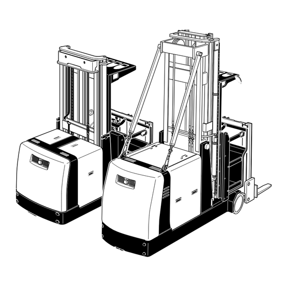
Assemblies and Functional Description EKS 513 / 515k / 515 EKS 410 Item Description Mast Aux. lift Control panel Height-adjustable driver’s position Chassis t = Standard equipment o = Optional Equipment... -
Page 14: Truck
Truck Safety mechanisms: An enclosed truck geometry with rounded edges ensures safe handling of the truck. The overhead guard protects the driver from falling objects. The Emergency Disconnect switch immediately cuts out all truck movements in hazardous situations. Safety gates on either side of the cab disable all truck movements as soon as they are opened. -
Page 15: Standard Version Specifications
Hydraulic system: All hydraulic movements are controlled by a maintenance-free AC motor with a flanged low emission gear pump. Oil is distributed via magnetic switch valves. The varying oil requirements are controlled by the speed of the motor. During a lowering operation the hydraulic pump drives the motor which then acts as a generator (regenerative lowering). -
Page 17: Dimensions (As Per Data Plate)
Dimensions (as per data plate) Description 515k Mast height 3100 2955 2955 3705 (retracted) Lift 4000 3500 3500 5000 Mast height 6550 6050 6050 7550 (extended) Seat height / standing height Aux. lift Overall lift 4840 4340 4340 5840 Stockpicking height 5995 5570 5570... -
Page 18: Eks 410 Mast Version
EKS 410 mast version Description EKS 410 Retracted height (ZT) 2550 - 4100 mm Lift 2500 - 6000 mm Extended height 5050 - 8550 mm Height above overhead 2550 guard Aux. lift Overall lift height 3340 - 6840 mm Stockpicking height 4495 - 7995 mm EKS 513 –... -
Page 19: En Norms
EN norms EKS 410 EKS 513 - 515 Noise emission: 61 dB(A) 68 dB(A) in accordance with EN 12053 as harmonised with ISO 4871. The noise emission level is calculated in accordance with standard procedures and takes into account the noise level when travelling, lifting and when idle. The noise level is measured at the driver’s ear. -
Page 20: Identification Points And Data Plates
Identification points and data plates Warning and information labels, such as capacity diagrams, attachment points and identification plates, must be readable at all times or be replaced, if necessary. EKS 410 h3 (mm) Q (kg) D (mm) 1,5 V Item Description... - Page 21 EKS 513 - 515 h3 (mm) Q (kg) D (mm) 1,5 V Item Description Strap points for crane lifting Truck data plate Capacity plate Decal: “Abseil device” Decal: “No passengers” Test sticker (o) Decal: Do not step onto or beneath the load, risk of trapping Jack contact points Serial number (engraved in chassis underneath the battery cover) “Add hydraulic oil”...
-
Page 22: Capacity
Truck data plate Item Description Item Description Type Manufacturer Serial no. Min./max. battery weight (kg) Rated capacity (kg) Drive output (kW) Battery voltage (V) Load centre of gravity (mm) Net weight w.o. battery (kg) Year of manufacture Manufacturer’s logo Option For queries relating to the truck or spare parts orders, please state the truck serial no. - Page 23 B 12...
-
Page 24: C Transport And Commissioning
The truck must only be lifted by crane with the battery removed. – Parking the truck securely (see Chapter E). Attach the crane slings to the strap points (1-3) so that the truck cannot slip. EKS 410 EKS 513 - 515... -
Page 25: Crane Points
(1) and (2) (for weight see data plate) – Crane points for the basic truck: items (2) and (3) (weight 2000 kg (EKS 410), 3000 kg (EKS 513-515) – Mast crane points including driver’s cab and load handler: items (1) and (3) (weight 2,600 kg (EKS 410), 6,500 kg (EKS 513-515) -
Page 26: Basic Truck Transport Safety
To ensure secure transport of a disassembled EKS, use the prescribed attachment points for fastening/quick release belts. With the EKS 410 only use straps with a rated capacity of > 5 tonnes and with the EKS 513-515 only straps with a rated capacity of > 9 tonnes. -
Page 27: Mast Transport Safety
Mast transport safety Use a transport retaining device (20) to prevent the operator compartment carriage (14) from sliding. If the mast is stored on a pallet(s), fasten them securely to the mast (18). Use the attachment latch (19) as the "mast bottom" strap point for securing to the lorry eyes (17). -
Page 28: Mast Assembled
(minimum chassis width). In addition, secure the load wheels with a wedge (24). Only use belts with a rated capacity of . EKS 410 > 5 to EKS 513 > 9 to At least 4 belts, 2 on the left and 2 on the right (20, 21) must be attached to the mast. -
Page 29: Commissioning
– Commission the truck as per instructions (See Chapter E, Section 3). With the EKS 410/513/515k/515 a tipover retaining device (30) is fitted, depending on the tipover test. When a tipover retaining device is used, an X (29) is engraved on the truck chassis on the right hand side of the battery compartment, after the serial number. -
Page 30: D Battery Maintenance, Charging & Replacement
D Battery Maintenance, Charging & Replacement Safety regulations for handling acid batteries Park the industrial truck securely before carrying out any work on the batteries (see Chapter E). Maintenance personnel: Batteries may only be charged, serviced or replaced by trained personnel. The present operator manual and the manufacturer’s instructions concerning batteries and charging stations must be observed when carrying out the work. -
Page 31: Battery Types
The EKS can be fitted with a variety of battery types. All battery types comply with DIN 43531-A. The following table shows which combinations can be included as standard: Battery type Battery type Truck type 48V 4EPzS460 Single part EKS 410 48V 4EPzS575 Single part EKS 410 48V 4EPzS690 Single part EKS 410 80V 3EPzS420... -
Page 32: Battery Removal And Installation
Only connect and disconnect the battery connector and the socket when the mains and charger are switched off. t EKS 410 (installing/removing a battery with a battery trolley): – Turn key switch (2) to "0" (zero). – Lift up the battery panels (4) and disconnect the battery (3). - Page 33 t EKS 513 - 515 (installing/removing a battery with a battery trolley): – Turn key switch (9) to "0" (zero). – Lift up the battery panel (11). – Pull the battery panels (12) up and lift them off. – Disconnect the battery (15). –...
- Page 34 o EKS 513 – 515 (Installing/removing batteries in the battery replacement carriage with a forklift): – Turn key switch (18) to "0" (zero). – Lift up the battery panel (20). – Pull the battery panels (21) up and lift them off. –...
-
Page 36: Battery - Checking Condition And Acid Level
Battery – checking condition and acid level – The battery manufacturer’s maintenance instructions apply. – Check the battery housing for cracks and any spilled acid. – Remove any oxydation remains from the battery terminals and apply an acid-free grease to the battery terminals. –... -
Page 38: Safety Regulations For The Operation Of Forklift Trucks
E Operation Safety Regulations for the Operation of Forklift Trucks Driver authorisation The forklift truck may only be used by suitably trained personnel, who have demonstrated to the proprietor or his representative that they can drive and handle loads and have been authorised to operate the truck by the proprietor or his representative. -
Page 39: Operating And Display Equipment
Operating and Display Equipment Operating and display equipment on control panel 10 11 12 22 21... - Page 40 Item Control / Display Function t All displays and functions Control panel t Switches control current on and off. Removing Key switch the key prevents the truck from being switched on by unauthorised personnel. t Sets the height and distance of the control Control panel stop panel.
-
Page 41: Display Unit Controls And Displays
Display unit controls and displays 26 27 Upper range symbols Item Symbol Control / Display Function Displays possible travel speeds: Turtle Rabbit Creep mode Max. travel speed “Guidance wire IG Sensors which have recognised the recognition” display guidance wire have a dark background Steering angle display Indicates the current steering angle with reference to the centre position... -
Page 42: Lower Range Symbols And Keys
Item Symbol Control / Display Function t Displays the height of the forks Display “Overall lift” “Referencing required” display: Primary raise - lift Requests Primary raise to lift Primary raise - lower Requests Primary raise to lower t Time display “Time”... - Page 43 Symbol Control or Display Function o Indicates that the personal safety system “Personalsafety system” display (PSS) has identified persons or objects in the aisle. The truck brakes. “Personalsafety system” Bypasses the protective function and switch (PSS) enables creep mode if there is sufficient distance from the obstacle.
-
Page 44: Truck Operational Status Symbols
Truck operational status symbols The operational status of the truck when it is switched on is indicated by symbols in the display unit. Safety gates open Foot switch not pressed When the following symbols are displayed you must carry out a reference movement in accordance with the display, i.e. -
Page 45: Starting Up The Truck
Starting up the truck Before the truck can be commissioned, operated or a load unit lifted, the driver must ensure that there is nobody within the hazardous area. Checks and operations to be performed before starting daily work – Check the whole of the outside of the truck for signs of damage and leaks. –... -
Page 46: Setting The Time
Setting the time Selecting the “Set Time” menu: Press switch 31, the display changes to the sub menu. Truck movements are inhibited in this sub-menu. Now press switch 32 twice; the “Set Time” menu now appears in the display unit. Setting the time: Simultaneously press switches 32 –and 33: to set the time forward by an hour. -
Page 47: Industrial Truck Operation
Industrial truck operation Safety regulations for truck operation Travel routes and work areas: Only use lanes and routes specifically designated for truck traffic. Unauthorised persons must stay away from work areas. Loads must only be stored in places specially designated for this purpose. Driving conduct: The driver must adapt the travel speed to local conditions. -
Page 48: Travelling, Steering, Braking
Travelling, Steering, Braking EMERGENCY DISCONNECT – Press EMERGENCY DISCONNECT switch (18) down. All truck movements are inhibited. The operation of the switch must not be affected by any objects placed in its way. Travel The truck can be driven in 3 modes: Free travel, with wire or rail guidance. - Page 49 Steering Use the steering wheel to steer the truck outside narrow aisles. The position of the drive wheel is shown in the display unit (9). Brakes The truck’s braking characteristics depend largely on the ground conditions. The driver must take this into consideration when handling the truck. –...
- Page 50 Negotiating narrow aisles It is forbidden for unauthorised personnel to enter narrow aisles (truck lanes in racking systems with safety distances < 500 mm) or for personnel to cross through them. These work areas must be marked and identified accordingly. Carry out a daily inspection of the safety mechanisms on the truck or the racking sysem to avoid hazards and protect personnel.
- Page 51 Wire guidance trucks When starting or continuing the truck after the wire guidance has been deactivated, note the position of the drive wheel as manual steering is now activated again. If an automatically guided truck is switched off, the wire guidance is no longer active when it is switched on again.
- Page 52 Inductive automatic steering takes over the steering of the truck and applies it to the guidance wire. Tracking is complete once the truck has been led precisely to the guidance wire. “Tracking on” (41) changes to “guidance wire applied” (42). The tracking signal is no longer sounded.
-
Page 53: Lifting-- Lowering Outside Narrow Aisles
Lifting–- lowering outside narrow aisles Risk of injury when the driver’s cab and the load handler are lowered. There must be nobody in the danger zone. Lift – Lower (Primary raise) – Apply the foot switch. – Turn the hydraulic control switch (8) Right = Lower Left = Lift lift... -
Page 54: Order Picking And Stacking
Order picking and stacking Collecting, transporting and depositing loads Before picking up a load unit the driver must make sure that it has been correctly palletised and does not exceed the truck’s capacity. Observe the load diagram. – Check the fork distance for the pallet and adjust if necessary. Adjusting the forks To pick up the load securely, the forks must be as far apart as possible and... - Page 55 Picking up a load from the front – Drive the truck slowly. – Slowly insert the forks into the pallet until the fork shank touches the load or the pallet. – Raise the load slightly and slowly reverse the truck. The ground surface must be in good condition to ensure this works correctly.
-
Page 56: Parking The Truck Securely
Parking the truck securely When you leave the truck it must be securely parked even if you only intend to leave it for a short time. Do not park the truck on an incline. In special cases the truck may need to be secured with wedges. -
Page 57: Troubleshooting
Troubleshooting This chapter enables the user to identify and rectify basic faults and the results of incorrect operation. When locating a fault, proceed in the order shown in the table. Fault Possible cause Action Truck does – Battery plug – Check the battery plug and connect if not start. - Page 58 Fault Possible cause Action Error 144 – Truck quit – Restore wire guidance guidance wire Error 330 – Travel control button – Do not press travel control button, switch pressed during power- truck off and on again up test Error 331 –...
-
Page 59: Emergency Stop Device
Emergency stop device When the automatic emergency stop mechanism applies (e.g. if the wire guidance is lost, electrical steering fails) the truck brakes to a halt. Before starting again, the cause of the error must be identified and corrected. Start the truck again in accordance with manufacturer’s instructions contained in these operating instructions (see “Starting up the Truck”... -
Page 60: Exiting The Driver's Cab With The Emergency Abseil Device
– Press the EMERGENCY DISCONNECT switch (18). – Remove the abseil device (50) on the EKS 410 from the compartment under the seat. on the EKS 513-515 from the compartment in the overhead guard. – Attach the karabiner hook (53) of the abseil device (left or right) to the eye (49) of the overhead guard. -
Page 61: Bypassing The Chain Slack Safety Device
Abseiling Do not drop into loose rope. Watch out for obstacles when abseiling. – Make the rope (52) taut. – Exit with your face towards the truck. – To abseil, press the lever (51) on the abseil device down. – To stop abseiling, release the brake lever (51). Bypassing the chain slack safety device If the slack chain safety device engages (the “Slack chain override”... -
Page 62: Lift Cutout (O)
Lift cutout (o) If local conditions require, an automatic lift cutout to apply from a given lift height can be fitted for safety reasons. The display unit shows the "Lift Cutout Override" symbol (59). Lift cutout only becomes effective after a test run has been carried out. -
Page 63: Wg Emergency Operation
WG emergency operation If in a wire guidance system the guiding antenna extends beyond the pre-determined range of the guidance wire, an emergency stop is immediately performed. If the truck is travelling directly parallel to the guidance wire, travel is not disabled. The “tracking on”... -
Page 64: Recovering The Truck From A Narrow Aisle / Moving The Truck Without A Battery
Recovering the truck from a narrow aisle / Moving the truck without a battery Before recovering the truck from a narrow aisle, disconnect the battery. This operation must only be performed by suitably trained maintenance personnel. When the brakes are de-activated the truck must be parked on an even ground as the brakes are no longer effective. - Page 65 Releasing the load wheel brake (hydraulic brake) - EKS 513 – 515 only – Remove the electronic compartment cover at the back. – Remove the protective cap from the bleed valve (68). – Remove the cover (64) from the brake fluid retainer. –...
- Page 66 Adjust the steering angle The battery must be disconnected when adjusting the steering angle. Using an Allen key set the steered wheel to the required direction via the screw in the steering motor (69). It is advisable to discharge the wheel if setting an angle greater than 4 degrees.
- Page 67 E 30...
-
Page 68: F Maintenance Of The Forklift Truck
F Maintenance of the forklift truck Operational safety and environmental protection The servicing and inspection duties contained in this chapter must be performed in accordance with the intervals indicated in the servicing checklists. Any modifications to the forklift truck assemblies, in particular the safety mechanisms, is prohibited. - Page 69 Electrical System: Only suitably trained personnel may operate on the truck’s electrical system. Before working on the electrical system, take all precautionary measures to avoid electric shocks. For battery-operated trucks, also de-energise the truck by removing the battery connector. Welding: To avoid damaging electric or electronic components, remove these from the truck before performing welding operations.
-
Page 70: Servicing And Inspection
The application conditions of an industrial truck considerably affect the wear levels of the service components. We recommend an application analysis carried out on site by a Jungheinrich customer adviser to establish specific maintenance intervals in order to restrict damage caused by wear. -
Page 71: Eks Maintenance Checklist
EKS Maintenance Checklist Maintenance intervals Standard = W A B C Chassis/ 1.1 Check all load bearing components for damage Structure: 1.2 Check screw connections 1.3 Test the operator’s platform and check for damage 1.4 Check that identification points, data plates and warnings are legible and replace if necessary 1.5 Check battery panel and sides are secure 1.6 Test gas pressure damper and check for damage... - Page 72 Maintenance intervals Standard = W A B C Hydraulic 6.1 Test operation System 6.2 Check connections and ports for leaks and damage 6.3 Check hydraulic cylinder for leaks and damage and make sure it is secure 6.4 Check oil level 6.5 Test hose guide and check for damage 6.6 Check ventilation and discharge filter on hydraulic reservoir...
- Page 73 Maintenance intervals Standard = W A B C Lift 10.1 Clean rollers, guide rollers and contact surfaces in the mechanism mast sections and apply grease. Attention: Danger of crashing! 10.2 Check mast attachments (bearings and retaining screws) 10.3 Check lift chains and chain guide for wear, adjust and lubricate 10.4 Lubricate lift chains 10.5 Visually inspect rollers, slide pieces and stops...
-
Page 74: Lubrication Schedule
Lubrication Schedule Grease nipple consumable E Outer mast (513 - 515) Driver’s position (513 – 515) Centre mast (513 - 515) Inner mast (513 - 515) Fork carriage (513 - 515) - Page 75 EKS 513 -515 EKS 410 a Transmission oil drain plug Contact surfaces Grease nipple Hydraulic oil filler neck c Hydraulic oil drain plug...
-
Page 76: Fuels, Coolants And Lubricants
Operating Manual. Avoid spillage. Spilled liquids must be removed immediately with suitable bonding agents and the bonding agent / consumable mixture must be disposed of in accordance with regulations. EKS 410 fuels and lubricants Quantity Code Order no. - Page 77 EKS 513/515k/515 fuels and lubricants Quantity Code Order no. Capacity Description Used for supplied 51037497 HLP D22 including 2 % 51037494 share additive 68 ID approx. Hydraulic System 110 l Plantohyd 22 S 51085361* (BIO hydraulic oil) approx. 50022968 SAE 80 EP API GL4 Transmission 5,8 l approx.
-
Page 78: Maintenance And Repairs
Maintenance and Repairs Load bearing parts of the truck, e. g. chassis and mast, may only be welded after consultation with the manufacturer. Prepare the truck for maintenance and repairs All necessary safety measures must be taken to avoid accidents when carrying out maintenance and repairs. -
Page 79: Lift Chain Servicing
Lift Chain Servicing It is important that all lift chains and pivots are at all times kept clean and well lubricated. Only lubricate discharged chains. A chain must be lubricated with particular care at the points where it passes over a pulley. Lift chains are safety- critical parts. -
Page 80: Hydraulic Oil
Hydraulic oil – Prepare the truck for maintenance and repairs Oil must never be allowed to enter the drainage system or the soil. Used oil must be preserved until it can be disposed of in the correct manner. Draining oil: Suction off the hydraulic oil with the discharge filter removed (5). -
Page 81: Hydraulic Hoses
Hydraulic hoses Hose lines must be replaced every six years, see Safety Regulations for Hydraulic Hose Lines ZH 1/74. Check brake fluid (EKS 513 - 515) Brake fluid is poisonous and should therefore only be stored in sealed, original containers. It should also be noted that brake fluid corrodes the truck paint. -
Page 82: Checking Electrical Fuses (Eks 410)
Checking electrical fuses (EKS 410) Electric fuses must only be checked and replaced by authorized personnel. – Prepare the truck for maintenance and repairs (see Chapter F). – Check all fuse ratings in accordance with the table; replace if necessary. -
Page 83: Checking Electrical Fuses (Eks 513 - 515)
Checking electrical fuses (EKS 513 - 515) Electric fuses must only be checked and replaced by authorized personnel. – Prepare the truck for maintenance and repairs (see Chapter F). – Check all fuse ratings in accordance with the table; replace if necessary. Only use the rating indicated on the controller. -
Page 84: Recommissioning
5.10 Recommissioning The truck may only be recommissioned after cleaning or repair work, once the following operations have been performed. – Test horn. – Test EMERGENCY DISCONNECT switch. – Test brake. Decommissioning the industrial truck If the industrial truck is to be decommissioned for more than one month, e.g. for operational reasons, it must be parked in a frost-free and dry location and all necessary measures must be taken before, during and after decommissioning as described. -
Page 85: During Decommissioning
During decommissioning: Every 2 months: – Charge the battery (see Chapter D). Battery powered trucks: The battery must be charged at regular intervals to avoid depletion of the battery through self-discharge. The sulfatisation would destroy the battery. Restoring the truck to operation after decommissioning –... -
Page 86: Safety Checks To Be Performed At Regular Intervals And Following Any Unusual Incidents
Carry out a safety check in accordance with national regulations. Junheinrich recommends checks in accordance with FEM Guideline 4.004. Jungheinrich has a special safety department with trained personnel to carry out such checks. The truck must be inspected at least annually (refer to national regulations) or after any unusual event by a qualified inspector. - Page 87 F 20...
- Page 88 Jungheinrich traction battery Table of contents Jungheinrich traction battery ..........2-6 with positive tubular plates type EPzS and EPzB Type plate Jungheinrich traction battery..........7 Instruction for use ............8-12 Aquamatic/BFS III water refilling system Jungheinrich traction battery Maintenance free traction batteries with positive tubular plates type EPzV ....................13-17...
- Page 89 Jungheinrich traction battery with positive tubular plates type EPzS and EPzB Rating Data 1. Nominal capacity C5: See type plate 2. Nominal voltage: 2,0 V x No of cells 3. Discharge current:: C5/5h 4. Nominal S.G. of electrolyte* Type EPzS:...
- Page 90 Ignoring the operation instructions, repair with non-original parts or using additives for the electrolyte will render the warranty void. For batteries in classes I and II the instructions for maintaining the appropriate protection class during operation must be complied with (see relevant certificate). 1.
- Page 91 Battery container lids and the covers of battery compartments must be opened or re- moved. The vent plugs should stay on the cells and remain closed. With the charger switched off connect up the battery, ensuring that the polarity is cor- rect.
- Page 92 3. Maintenance 3.1 Daily Charge the battery after every discharge. Towards the end of charge the electrolyte level should be checked and if necessary topped up to the specified level with purified water. The electrolyte level must not fall below the anti-surge baffle or the top of the separator or the electrolyte „min“...
- Page 93 5. Storage If batteries are taken out of service for a lengthy period they should be stored in the fully charged condition in a dry, frost-free room. To ensure the battery is always ready for use a choice of charging methods can be made: 1.
- Page 94 7. Type plate, Jungheinrich traction battery Baujahr T ype Year of manufacture Serien-Nr. Lieferanten Nr. Serial-Nr. Supplier No. Nennspannung Kapazität Nominal V oltage Capacity Zellenzahl Batteriegewicht min/max Number of Cells Battery mass min/max Hersteller Jungheinrich AG, D-22047 Hamburg, Germany Manufacturer...
- Page 95 Aquamatic/BFS III water refilling system for Jungheinrich traction battery with EPzS and EPzB cells with tubular positive plates Aquamatic plug arrangement for the Operating Instructions Cell series* Aquamatic plug type (length) EPzS EPzB Frötek (yellow) (black) 2/120 – 10/ 600 2/ 42 –...
- Page 96 Diagrammatic view Equipment for the water refilling system 1. Water tank 2. Level switch 3. Discharge point with ball valve 4. Discharge point with sole- noid valve 5. Charger 6. Sealing coupler 7. Closing nipple 8. Ion exchange cartridge with conductance meter and solenoid valve 9.
- Page 97 4. Filling (manual/automatic) The batteries should be filled with battery water as soon as possible before the battery charging comes to an end; this ensures that the refilled water quantity is mixed with the electrolyte. In normal operation it is usually sufficient to fill once a week. 5.
- Page 98 8. Battery hose connections Hose connections for the individual plugs are laid along the existing electric circuit. No changes may be made. 9. Operating temperature The temperature limit for battery operation is set at 55° C. Exceeding this temperature damages the batteries. The battery filling systems may be operated within a tempe- rature range of >...
- Page 99 10.2.1 Clamping ring tool The clamping ring tool is used to push on a clamping ring to increase the contact pres- sure of the hose connection on the plugs' hose couplings and to loosen it again. 10.3 Filter element For safety reasons a filter element (ident no.: 50307282) can be fitted into the batte- ry's main supply pipe for supplying battery water.
Need help?
Do you have a question about the EKS 410 and is the answer not in the manual?
Questions and answers