Table of Contents
Advertisement
Advertisement
Chapters
Table of Contents

Related Manuals for Jungheinrich EJC M10


Summary of Contents for Jungheinrich EJC M10
- Page 1 EJC M10 05.09 - Operating instructions 51145321 05.09...
- Page 2 Used to indicate standard equipment. Used to indicate optional equipment. Our trucks are subject to ongoing development. Jungheinrich reserves the right to alter the design, equipment and technical features of the truck. No guarantee of particular features of the truck should therefore be inferred from the present operating instructions.
-
Page 4: Table Of Contents
Table of contents Correct Use and Application Description Application ................... B 1 Assemblies ..................B 2 Technical Specifications ..............B 3 Performance data ................B 3 Dimensions ..................B 3 EN norms .................... B 5 Conditions of use ................B 5 Identification points and data plates ............ - Page 5 Travel parameters ................E 11 Display instrument (CanDis) (o) ............E 12 Service hours display ................E 13 Power up test ..................E 13 Troubleshooting .................. E 14 Industrial Truck Maintenance Operational Safety and Environmental Protection ......F 1 Maintenance Safety Regulations ............F 1 Servicing and Inspection ..............
- Page 6 Appendix JH Traction Battery Operating Instructions These operating instructions apply only to Jungheinrich battery models. If using another brand, refer to the manufacturer's operating instructions.
-
Page 8: A Correct Use And Application
A Correct Use and Application The “Guidelines for the Correct Use and Application of Industrial Trucks” (VDMA) are supplied with the truck. The guidelines form part of these operating instructions and must be observed. National regulations apply in full. The truck described in the present operating instructions is an industrial truck designed for lifting and transporting loads. -
Page 10: B Description
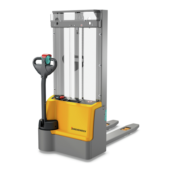
B Description Application The EJC M10 is a four wheel, electric pedestrian stacker with a steered drive wheel. It is designed for use on level floors to lift and transport palletised goods. Open bottom pallets or roll cages can be lifted. -
Page 11: Assemblies
Assemblies Item EJC M10 Description Key switch Battery charge / discharge indicator CANDIS display instrument Tiller and tiller arm “Shunt” button Controller Collision safety switch Mast Mast guard / auxiliary mast guard Battery cover Battery connector (Emergency Disconnect) Lift mechanism... -
Page 12: Technical Specifications
Technical Specifications Technical specification details in accordance with VDI 2198. Technical modifications and additions reserved. Performance data Description EJC M10 Rated capacity 1000 Load centre distance Standard fork length Travel speed w. rated load / w.o. load 4.2 / 5.0... -
Page 14: En Norms
EN norms Noise emission: 70 dB(A) in accordance with EN 12053 as harmonised with ISO 4871. The noise emission level is calculated in accordance with standard procedures and takes into account the noise level when travelling, lifting and when idle. The noise level is measured at the level of the driver's ear. -
Page 15: Identification Points And Data Plates
Identification points and data plates Item Description Capacity Data plate Strap point for crane lifting "Do not reach through the mast" warning “Do not step under the load handler” warning Battery data plate Serial number Truck description “No riding” warning Test plaque (o) -
Page 16: Capacity
Data Plate Item Description Item Description Type Manufacturer’s logo Serial no. Min./max. battery weight (kg) Rated capacity (kg) Output (kW) Battery voltage (V) Load centre of gravity (mm) Net weight excl. battery Year of manufacture Manufacturer Option For truck-related queries or when ordering spare parts always quote the truck serial number (26). -
Page 18: C Transport And Commissioning
C Transport and Commissioning Lifting by crane Only use lifting gear with sufficient capacity (for transport weight see truck data plate). The attachment points (1) are provided for lifting the truck with crane lifting gear (in the middle on the ZZ mast). –... -
Page 19: Using The Truck For The First Time
Using the truck for the first time Only operate the truck with battery current. Rectified AC current will damage the electronic components. The battery leads (tow cable) must be less than 6m long. Do not lift loads if the truck is operated via a tow lead with an external battery. To prepare the truck after delivery or after transport, proceed as follows: –... -
Page 20: Operating The Truck Without Its Own Drive System (Emergency Operation)
Operating the truck without its own drive system (emergency operation) This operating mode is not permitted when negotiating inclines and gradients. If the truck has to be moved after a fault has made it non-operational, proceed as follows: – Set the main switch/isolator “OFF”. –... -
Page 22: D Battery Maintenance, Charging & Replacement
D Battery Maintenance, Charging & Replacement Safety regulations for handling acid batteries Park the industrial truck securely before carrying out any work on the batteries (see Chapter E). Maintenance personnel: Batteries may only be charged, serviced or replaced by trained personnel. This operator manual and the manufacturer’s instructions concerning batteries and charging stations must be observed when carrying out the work. -
Page 23: Battery Types
When replacing or installing batteries, ensure that the battery is correctly secured in the battery compartment of the truck. The following table shows which combinations are included as standard: Battery EJC M10 2 PzB 110 Ah Exposing the battery – Park the truck securely (see Chapter E). -
Page 24: Charging The Battery
Charging the battery The on-board charger must not be opened. The mains cable must not be damaged. It is essential to follow the safety regulations of the battery and charging station manufacturers. The mains cable of the charger is located in the mains cable holder in the battery compartment. - Page 25 LED display (4) Charging complete, battery fully charged. (charge interval, float or compensation charge) Flashes slowly Charging Rapid flash Display at beginning of charge or after setting a new characteristic curve. Number of flash pulses corresponds to the characteristic curve set. Red LED (fault) Overtemperature.
-
Page 26: Charging The Battery With A Stationary Charger (O)
Charging the battery with a stationary charger (o) Park the truck securely (see Chapter E). The battery connector and socket may only be attached or disconnected when the main switch and the charger are switched off. – Expose the battery (see section 3). When charging, the tops of the battery cells must be exposed to provide sufficient ventilation. -
Page 27: Battery Removal And Installation
Battery removal and installation – Undo the spring elements of the battery panel and remove the battery panel. The truck must be level. To prevent short circuits, batteries with exposed terminals or connectors must be covered with a rubber mat. Place the battery connector or the battery cable in such a way that they will not get caught on the truck when the battery is removed. -
Page 28: Battery Charge / Discharge Indicator (T)
Battery charge / discharge indicator (t) After the truck has been released via the key switch or CanCode, the battery charge status is displayed. The colours of the LEDs (6) represent the following conditions: LED colour Rating Green Capacitance 40 - 100 % Orange Capacitance 30 - 40 %... -
Page 30: E Operation
E Operation Safety Regulations for the Operation of Forklift Trucks Driver authorisation: The forklift truck may only be used by suitably trained personnel, who have demonstrated to the proprietor or his representative that they can drive and handle loads and have been authorised to operate the truck by the proprietor or his representative. -
Page 31: Controls And Displays
Controls and Displays Item Control / EJC M10 Function display item Battery connector Disconnects the circuit, all electrical functions (Emergency are deactivated. The truck stops. Disconnect) Key switch Switches control current on and off. Removing the key prevents the truck from being switched on by unauthorised personnel. -
Page 33: Starting Up The Truck
Starting up the truck Before the truck can be started, operated or a load lifted, the driver must ensure that there is nobody within the hazardous area. Checks and operations to be performed before starting daily operation – Visually inspect the entire truck (in particular wheels and load handler) for obvious damage. -
Page 34: Industrial Truck Operation
Industrial Truck Operation Safety regulations for truck operation Travel routes and work areas: Only use lanes and routes specifically designated for truck traffic. Unauthorised third parties must stay away from work areas. Loads must only be stored in places specially designated for this purpose. Travel conduct: The driver must adapt the travel speed to local conditions. -
Page 35: Travel, Steering, Braking
Travel, steering, braking Never carry passengers. Emergency Disconnect – Remove the battery connector (1). All electrical functions are deactivated. Automatic braking The truck automatically brakes when the tiller is released – the tiller automatically sets itself to the upper brake zone (B). If the tiller moves slowly to the upper brake zone, the cause of this fault must be rectified. - Page 36 Crawl speed The driver must be particularly careful when applying the “Crawl speed” button (5). The truck can be operated with a vertical tiller (4) (e.g. in congested areas / travel seat). – Press the crawl speed button (5). – Set the controller (6) to the required direction (fwd. or rev.). The brake is released.
- Page 37 Braking The brake pattern of the truck depends largely on the track conditions. The driver must take this into account. Braking with the service brake: – Set the tiller (4) up or down to one of the brake zones (B). The service brake is the regenerative brake.
-
Page 38: Lifting And Depositing Load Units
Lifting and depositing load units Before lifting a load the driver must make sure that it has been correctly palletised and does not exceed the truck’s capacity. – Travel with the forks as far as possible underneath the load. Lifting –... -
Page 39: Emergency Lowering
Emergency lowering Keep all personnel out of the hazardous area when applying emergency lowering. If the mast cannot be lowered any further due to a fault, apply emergency lowering on the hydraulic unit. – Set key switch (2) to “0”. –... -
Page 40: Travel Parameters
Travel parameters This travel parameters can only be adjusted by the manufacturer’s service department. The following example shows the parameter setting for the acceleration of travel program 1 (parameter 101). Travel program 1 Function Setting Standard Comments range setting Acceleration 0 - 9 (0.1 –... -
Page 41: Display Instrument (Candis) (O)
Display instrument (CanDis) (o) The instrument shows: 16 Capacity display bars Battery residual charge status 17 Stop symbol; lift cutout, Battery charge required 18 6 digit LCD display; hourmeter, input display, error display 19 T symbol appears during operation when the discharge indicator is set to maintenance-free battery 20 Warning - pre-warning symbol, Battery charge recommended... -
Page 42: Service Hours Display
Service hours display Display range between 0.0 and 99,999.0 hours. Travel and lifting operations are logged. This is a backlit display. For maintenance-free batteries a “T” symbol is shown in the service hours display (19). Eventmessages The service hours display is also used to display events. The event display starts with an "E"... -
Page 43: Troubleshooting
Troubleshooting This chapter allows the user to identify and rectify basic faults or the effects of incorrect operation. When trying to locate a fault, proceed in the order shown in the table. Fault Possible Cause Action Truck does not – Battery connector not plugged –... -
Page 44: F Industrial Truck Maintenance
F Industrial Truck Maintenance Operational Safety and Environmental Protection The servicing and inspection duties contained in this chapter must be performed in accordance with the intervals indicated in the maintenance checklists. Any modification to the forklift truck assemblies, in particular the safety mechanisms, is prohibited. - Page 45 Electrical System: Only suitably trained personnel may operate on the truck's electrical system. Before working on the electrical system, take all precautionary measures to avoid electric shocks. Battery-operated trucks must also be de- energised by disconnecting the battery. Welding: To avoid damaging electric or electronic components, remove these from the truck before performing welding operations.
-
Page 46: Servicing And Inspection
Servicing and Inspection Thorough and expert servicing is one of the most important requirements for the safe operation of the industrial truck. Failure to perform regular servicing can lead to truck failure and poses a potential hazard to personnel and equipment. The service intervals stated are based on single shift operation under normal operating conditions. -
Page 47: Maintenance Checklist
Maintenance Checklist Maintenance Intervals = t W A B C Standard Brakes 1.1 Test service and/or parking brakes. 1.2 Check magnetic brake air gap, adjust if necessary Electrical sys- 2.1 Test warning indicators and safety devices. 2.2 Test cable and motor attachments 2.3 Test instruments, displays and control switches. - Page 48 Maintenance Intervals Standard W A B C Hydraulic oper- 6.1 Check cylinders and piston rods for damage ations and leaks, and make sure they are secure. 6.2 Check settings and wear levels of slide pieces and stops, and adjust if necessary 6.3 Check load chain setting and tension if necessary 6.4 Visually inspect mast rollers and check contact surface wear level...
-
Page 49: Lubrication Schedule
Lubrication Schedule E / F A (C) 4,5 l 0,55 l Contact surfaces Hydraulic oil filler neck Transmission oil filler neck Gear oil overflow and dipstick Transmission oil drain plug... -
Page 50: Consumables
The Jungheinrich hydraulic oil can only be obtained from the Jungheinrich service department. The use of named alternative hydraulic oils is not prohibited but may lead to a decline in functionality. The Jungheinrich hydraulic oil may be mixed with one of the named alternative hydraulic oils. -
Page 51: Maintenance Instructions
Maintenance Instructions Preparing the truck for maintenance and repairs All necessary safety measures must be taken to avoid accidents when carrying out maintenance and repairs. The following preparations must be made: – Park the truck securely (see Chapter E). – Remove the battery connector (1) to prevent the truck from accidentally starting. When working under a raised lift truck, secure it to prevent it from tipping or sliding away. -
Page 52: Checking The Hydraulic Oil Level
Checking the hydraulic oil level – Prepare the truck for maintenance and repairs (see section 6.1). – Remove the front panel (see section 6.2). – Check hydraulic oil level in hydraulic reservoir. There are markings on the hydraulic reservoir. The oil level must be checked when the load forks are lowered. -
Page 53: Checking Electrical Fuses
Checking electrical fuses – Prepare the truck for maintenance and repairs (see section 6.1). – Remove the front panel (see section 6.2). – Check the fuse rating and condition in accordance with the table; replace if necessary. Item Description To protect: Rating Pump motor fuse 100 A... -
Page 54: Recommissioning
Recommissioning The truck may only be restored to service after cleaning or repair work, once the following operations have been performed. – Test horn. – Test Emergency Disconnect. – Test brakes. – Lubricate according to the maintenance schedule. Decommissioning the industrial truck If the industrial truck is to be decommissioned for more than two months, e.g. -
Page 55: Returning The Truck To Operation After Decommissioning
Safety tests to be performed at intervals and after unusual incidents Perform a safety check in accordance with national regulations. Jungheinrich recommends the truck be checked to FEM guideline 4.004. Jungheinrich has a safety department with trained personnel, able to carry out inspections. - Page 56 Jungheinrich traction battery Table of contents Jungheinrich traction battery ..........2-6 with positive tubular plates type EPzS and EPzB Type plate Jungheinrich traction battery..........7 Instruction for use ............8-12 Aquamatic/BFS III water refilling system Jungheinrich traction battery Maintenance free traction batteries with positive tubular plates type EPzV ....................13-17...
-
Page 57: Jungheinrich Traction Battery
Jungheinrich traction battery with positive tubular plates type EPzS and EPzB Rating Data 1. Nominal capacity C5: See type plate 2. Nominal voltage: 2,0 V x No of cells 3. Discharge current:: C5/5h 4. Nominal S.G. of electrolyte* Type EPzS:... - Page 58 Ignoring the operation instructions, repair with non-original parts or using additives for the electrolyte will render the warranty void. For batteries in classes I and II the instructions for maintaining the appropriate protection class during operation must be complied with (see relevant certificate). 1.
- Page 59 Battery container lids and the covers of battery compartments must be opened or re- moved. The vent plugs should stay on the cells and remain closed. With the charger switched off connect up the battery, ensuring that the polarity is cor- rect.
- Page 60 3. Maintenance 3.1 Daily Charge the battery after every discharge. Towards the end of charge the electrolyte level should be checked and if necessary topped up to the specified level with purified water. The electrolyte level must not fall below the anti-surge baffle or the top of the separator or the electrolyte „min“...
- Page 61 5. Storage If batteries are taken out of service for a lengthy period they should be stored in the fully charged condition in a dry, frost-free room. To ensure the battery is always ready for use a choice of charging methods can be made: 1.
-
Page 62: 7. Type Plate, Jungheinrich Traction Battery
7. Type plate, Jungheinrich traction battery Baujahr T ype Year of manufacture Serien-Nr. Lieferanten Nr. Serial-Nr. Supplier No. Nennspannung Kapazität Nominal V oltage Capacity Zellenzahl Batteriegewicht min/max Number of Cells Battery mass min/max Hersteller Jungheinrich AG, D-22047 Hamburg, Germany Manufacturer... -
Page 63: Aquamatic/Bfs Iii Water Refilling System
Aquamatic/BFS III water refilling system for Jungheinrich traction battery with EPzS and EPzB cells with tubular positive plates Aquamatic plug arrangement for the Operating Instructions Cell series* Aquamatic plug type (length) EPzS EPzB Frötek (yellow) (black) 2/120 – 10/ 600 2/ 42 –... - Page 64 Diagrammatic view Equipment for the water refilling system 1. Water tank 2. Level switch 3. Discharge point with ball valve 4. Discharge point with sole- noid valve 5. Charger 6. Sealing coupler 7. Closing nipple 8. Ion exchange cartridge with conductance meter and solenoid valve 9.
- Page 65 4. Filling (manual/automatic) The batteries should be filled with battery water as soon as possible before the battery charging comes to an end; this ensures that the refilled water quantity is mixed with the electrolyte. In normal operation it is usually sufficient to fill once a week. 5.
- Page 66 8. Battery hose connections Hose connections for the individual plugs are laid along the existing electric circuit. No changes may be made. 9. Operating temperature The temperature limit for battery operation is set at 55° C. Exceeding this temperature damages the batteries. The battery filling systems may be operated within a tempe- rature range of >...
- Page 67 10.2.1 Clamping ring tool The clamping ring tool is used to push on a clamping ring to increase the contact pres- sure of the hose connection on the plugs' hose couplings and to loosen it again. 10.3 Filter element For safety reasons a filter element (ident no.: 50307282) can be fitted into the batte- ry's main supply pipe for supplying battery water.
-
Page 68: Jungheinrich Traction Battery
Jungheinrich traction batterie Maintenance free Jungheinrich traction batterie with positive tubular plates type EPzV and EPzV-BS Rating Data 1. Nominal capacity C5: See type plate 2. Nominal voltage: 2,0 Volt x No of cells 3. Discharge current: C5/5h 4. Rated temperature: 30°... - Page 69 Ignoring the operation instructions, repair with non-original parts and non authorised interventions will render the warranty void. For batteries in classes I and II the instructions for maintaining the appropriate protection class during operation must be complied with (see relevant certificate). 1.
- Page 70 With the charger switched off connect up the battery, ensuring that the polarity is cor- rect (positive to positive, negative to negative). Now switch on the charger. When charging the temperature of the battery rises by about 15° C, so charging should only begin if the battery temperature is below 35°...
- Page 71 3.2 Weekly Visual inspection after recharging for signs of dirt and mechanical damage. 3.3 Quarterly After the end of the charge and a rest time of 5 h following should be measured and recorded: • the voltages of the battery •...
-
Page 72: 7. Type Plate, Jungheinrich Traction Battery
Batteries with this sign must be recycled. Batteries which are not returned for the recycling process must be disposed of as hazardous waste! We reserve the right make technical modification. 7. Type plate, Jungheinrich traction battery Baujahr T ype Year of manufacture Serien-Nr.
Need help?
Do you have a question about the EJC M10 and is the answer not in the manual?
Questions and answers
I own an EJCM10 electric pallet truck, and the motor is fitted with a 6204-type bearing that includes an integrated sensor. The bearing needs replacement, but I am unable to identify the exact specifications (sensor type, full part number, etc.). Could you please provide the following information: The exact OEM part number or full designation of the original bearing, The type of sensor integrated (speed, position, etc.), Whether you offer a replacement part or compatible equivalent. Thank you in advance for your assistance. P.S. I'm from Romania