Table of Contents
Advertisement
Quick Links
Download this manual
See also:
Operator's Manual
Advertisement
Table of Contents

Related Manuals for Dionex ICS-90


Summary of Contents for Dionex ICS-90
- Page 1 ICS-90 Ion Chromatography System Installation Instructions Document No. 031856 Revision 03 December 2006...
- Page 2 Dionex Corporation, 1228 Titan Way, Sunnyvale, California 94088-3603 U.S.A.
-
Page 3: Table Of Contents
Connecting the Power Cord ........13 Turning on the ICS-90 Power ....... . 14 Setting Up the Chromatography Software . - Page 4 2.17 Operating the ICS-90 ........
-
Page 5: Facility Requirements
This manual provides instructions for the initial installation of the ICS-90 Ion Chromatography System (ICS-90). Follow these installation instructions step-by- step, in the order specified. A newer version of the ICS-90, called the ICS-90A, has a feature that allows the approximate flow rate to be displayed in Chromeleon Chromatography ®... -
Page 6: Unpacking The Ics-90 System
3. Remove the foam cover. 4. Using the cardboard side handles, carefully remove the ICS-90 from the box. You may need to remove the foam at the sides of the ICS-90 before you can lift the instrument from the box. -
Page 7: Removing The Pump Shipping Screw
1.2.2 Removing the Pump Shipping Screw 1. Carefully lay the ICS-90 on its back or side. 2. Locate the middle screw on the bottom of the ICS-90 (see Figure 1-1). This screw secures the pump in place during shipment. 3. Use a Phillips screwdriver to remove the shipping screw. - Page 8 2. Chromeleon and Chromeleon Xpress run under the Microsoft® Windows® XP and Windows® 2000 operating systems. Refer to http://www.dionex.com to verify that the PC meets current system specifications. 3. Follow the instructions in the computer installation guide to hook up the PC components.
-
Page 9: Installing The Ics-90 System
Installing the Software NOTE Dionex strongly recommends installing Chromeleon or Chromeleon Xpress chromatography software before connecting the ICS-90 to the computer on which the software is installed. When the chromatography software is installed first, USB driver information is loaded automatically and the Windows operating system will detect the ICS-90 when the power is turned on. - Page 10 Finish. Troubleshooting Tip If a Microsoft Windows message box asks for the USB configuration file (cmwdmusb.inf), it indicates that you connected the ICS-90 to the PC and turned on the ICS-90 power before installing Chromeleon or Chromeleon Xpress.
-
Page 11: Installing The Software License
2 • Installing the ICS-90 System 2. Turn off the power to the ICS-90 and unplug the USB cable from the computer. 3. Install Chromeleon or Chromeleon Xpress. 4. Reconnect the USB cable to the computer and turn on the power to the ICS-90. - Page 12 ICS-90 Installation Instructions • If Chromeleon or Chromeleon Xpress was installed on the computer before shipping, the Server Monitor status will display “Chromeleon Server is running idle.” (This is because the license Key Code was entered before shipping.) If this is the case, click Close and go Section 2.5.1...
- Page 13 2 • Installing the ICS-90 System 4. Select Edit > Properties to open the Server Configuration properties dialog box (see Figure 2-2). Click Dongle and then enter the Key Code provided with the Chromeleon license. Click OK. Figure 2-2. Server Configuration Properties 5.
-
Page 14: Starting The Chromeleon Server Monitor
ICS-90 Installation Instructions 2.1.3 Starting the Chromeleon Server Monitor 1. If the Chromeleon Server Monitor program did not start automatically, start it now by double-clicking the Server Monitor icon on the Windows taskbar. If the Server Monitor icon is not on the taskbar, click Start on the taskbar and select All Programs (or Programs, depending on the operating system) >... -
Page 15: Connecting The Ics-90 To The Computer
Connect the ICS-90 directly to a USB port on the PC. • If there are no unused USB ports on the PC, connect the ICS-90 to an external USB hub (P/N 060392) and connect the PC to the hub. If the dongle provided with Chromeleon or Chromeleon Xpress is for a USB port, remember to reserve a USB port on either the PC or the hub for the dongle. - Page 16 ICS-90 Installation Instructions To connect the ICS-90 directly to the PC: 1. Locate the USB cable (P/N 960777) provided in the ICS-90 Ship Kit (P/N 059947). 2. Plug the “A” connector of the USB cable into the USB port on the PC...
-
Page 17: Connecting The Power Cord
4. Plug the “B” connector of the cable into a port on the USB hub. Connecting the Power Cord 1. A label on the ICS-90 rear panel indicates the line frequency (60 Hz or 50 Hz) and voltage (110 to 120 VAC or 220 to 240 VAC) for which the system is designed. -
Page 18: Turning On The Ics-90 Power
Windows 2000 as an administrator. If this is a network computer, log on as a user with local computer administrator privileges. 2. Turn on the power to the ICS-90. The operating system automatically detects the new USB device. A message flashes on the screen to inform you that the device was detected. -
Page 19: Setting Up The Chromatography Software
2 • Installing the ICS-90 System Setting Up the Chromatography Software 2.5.1 Creating a Timebase 1. In the Server Configuration program, select Edit > Add Timebase. 2. A clock icon appears under the server name with a default name highlighted. To use the default name, press Enter. To use a different name, type the name and press Enter. - Page 20 ICS-90 Installation Instructions 4. Select ICS-90 IC System from the list and click OK. A dialog box appears. Figure 2-9. ICS-90 Configuration Properties: Live Mode 5. On the General tab page, Live Mode is selected by default. Select the ICS-90 serial number from the drop-down list. If you are...
- Page 21 2 • Installing the ICS-90 System 6. Click Options to display the Options tab page. 7. Select the conductivity range (0 to 500 μS or 0 to 10,000 μS) from the drop-down list under Set Detection Limits. Selecting the larger (coarse) range reduces the detector’s resolution by a factor of 20.
-
Page 22: Connecting To The Control Panel
3. To display the ICS-90 (or ICS-90A) Control panel (see Figure 2-10), select the ICS-90 tab on the panel tabset. (The ICS-90A Control panel includes a Wellness Panel button; otherwise, the panels are identical.) Figure 2-10. ICS-90 Control Panel on the Panel Tabset... - Page 23 Control panel opens and connects automatically to the ICS-90 timebase. 5. If the Control panel opens with the controls not yet active, connect the ICS-90 to the Control panel by clicking the Connect button. A dialog box appears (see Figure 2-11).
-
Page 24: Verifying Communication With The Ics-90
ICS-90, click the and then the button on the Disconnect Connect Control panel while observing the ICS-90 front panel LEDs. If the ICS-90 and the chromatography software are communicating correctly, the LEDs are on when the ICS-90 is Power... -
Page 25: Connecting The Waste Lines
2 • Installing the ICS-90 System Connecting the Waste Lines Untape the coiled waste and liquid lines from the rear panel. Place the ends of the three waste lines into a waste container. The waste lines siphon off prime waste from the pump head, sample overflow from the injection valve, and system waste from the suppressor. -
Page 26: Connecting The Gas Source
Connecting the Gas Source 1. Locate the barbed fitting (P/N 030071), pipe thread reducer (P/N 030087), 3-mm (1/8-in) ID tubing (P/N 040793), and ICS-90 air regulator accessory (P/N 060054) in the ICS-90 Ship Kit. 2. Use the barbed fitting and pipe thread reducer to connect the 3-mm (1/8-in) ID tubing to a clean gas source. -
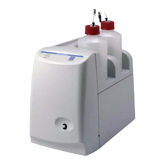
Page 27: Setting Up The Eluent And Regenerant Reservoirs
The regenerant reservoir must be filled all the way to the top at all times. e. Insert the stopper assembly tubing into the reservoir and tighten the stopper. Do not shake the regenerant reservoir to mix the contents. The ICS-90 will stratify the contents. Doc. 031856-03 12/06... - Page 28 6. Install the caps on the eluent and regenerant reservoirs and hand tighten. 7. Place the reservoirs in the holders on the top cover of the ICS-90. 8. Connect the liquid lines from the ICS-90 to the lines exiting the eluent and regenerant reservoir caps (see...
-
Page 29: Installing And Plumbing The Columns And Suppressor
2 • Installing the ICS-90 System 9. To ensure the correct operating pressure for the suppressor, either one or two backpressure coil(s) (P/N 045877) must be installed between the cell outlet and the regenerant reservoir inlet. The number of coils required depends upon... - Page 30 Brackets Cell Out Union Do not Verify that 1 remove or 2 back- pressure coils are installed (not shown in photo) Column In/Out Union (remove) Guard In/Out Union (remove) Figure 2-16. ICS-90 Component Panel (Door not shown) Doc. 031856-03 12/06...
- Page 31 Guard Column line Figure 2-17. ICS-90 with Columns and Suppressor Installed 4. To ensure the correct operating pressure for the suppressor, either one or two backpressure coil(s) (P/N 045877) must be installed between the cell outlet and the regenerant reservoir inlet. The number of coils required depends upon...
-
Page 32: Pressurizing The Eluent Reservoir
ICS-90 Installation Instructions a. For flow rates less than 2 mL/min, verify that two coils are installed. b. For flow rates of 2 mL/min or more, remove one of the backpressure coils. NOTE Refer to the flier Backpressure Coil Pressure Test for... -
Page 33: Priming The Pump
2 • Installing the ICS-90 System 2.11 Priming the Pump 1. Verify that the eluent and regenerant reservoirs are filled, the reservoir caps are installed and hand-tightened, and the gas and liquid lines are connected to the reservoirs (see Section 2.8). -
Page 34: Setting The Pump Flow Rate (Ics-90 Only)
2.12 Setting the Pump Flow Rate (ICS-90 only) The instructions in this section apply to the ICS-90 only. If you are unsure whether your system is an ICS-90 or ICS-90A, check the model data label on the rear panel. 2.12.1 Setting the Flow Rate 1. - Page 35 Volumetric Method 1 (Recommended): Using a Syringe and Adapter a. Locate the following items in the ICS-90 Ship Kit: luer fitting (P/N 024305), luer coupler (P/N 042806), 1 mL syringe (P/N 016388), and 10 mL syringe (P/N 016387). You will also need a stopwatch or a clock or watch with a second hand (the computer’s clock can be used),...
- Page 36 ICS-90 Installation Instructions e. Using a stopwatch or clock’s second hand, time the flow of eluent into the syringe for 60 seconds. Determine the volume collected by noting the beginning and ending positions of the syringe plunger. The volume of eluent collected in 60 seconds should be approximately equal to the desired flow rate in milliliters per minute.
-
Page 37: Recording The Measured Flow Rate
2 • Installing the ICS-90 System 2.12.2 Recording the Measured Flow Rate 1. From the ICS-90 Control panel, press the F8 key or select Control > Command. 2. Expand the Pump_ECD group and select MeasuredFlowRate (see Figure 2-20). Figure 2-20. ICS-90 Chromeleon Commands: MeasuredFlowRate 3. -
Page 38: Setting The Pump Flow Rate (Ics-90A Only)
1. After priming the pump and adjusting the flow rate, leave the pump on and flush the system for about 5 minutes to equilibrate. 2. Monitor the system pressure from the ICS-90 (or ICS-90A) Control panel to make sure the pressure is between 107 and 153 MPa (1600 and 2300 psi). If the pressure is less than 107 MPa (1600 psi), gas may be trapped in the system. -
Page 39: Verifying Operational Status
0.13 MPa (20 psi). 2.16 Connecting the AS40 Automated Sampler (Optional) 1. Open the front door of the ICS-90 and thread the outlet line from the AS40 through the side slot near the lower ICS-90 door hinge (see Figure 2-17). -
Page 40: Operating The Ics-90
Chromatography System Operator’s Manual (Document No. 031851). 2.18 Installation Troubleshooting Problem: When the ICS-90 power is turned on for the first time, a Windows message box appears asking for a USB configuration file (cmwdmusb.inf). Possible Cause: The USB cable was connected and the power turned on before Chromeleon or Chromeleon Xpress was installed.
Need help?
Do you have a question about the ICS-90 and is the answer not in the manual?
Questions and answers