
Related Manuals for Dionex ICS-3000


Summary of Contents for Dionex ICS-3000
- Page 1 ICS-3000 Ion Chromatography System Operator's Manual Document No. 065031 Revision 04 January 2008...
- Page 2 Dionex Corporation, 1228 Titan Way, Sunnyvale, California 94088-3603 U.S.A.
-
Page 3: Table Of Contents
1 • Introduction ICS-3000 System Overview ........1 1.1.1... - Page 4 ICS-3000 Ion Chromatography System DP/SP Flow Schematics ........23 2.3.1...
- Page 5 Contents 2.16.2 Combination pH–Ag/AgCl Reference Electrode ... 58 2.16.3 DC Amperometric Detection ......60 2.16.4 Integrated and Pulsed Amperometric Detection .
- Page 6 ICS-3000 Ion Chromatography System 2.24 Gas and Humidity Sensors ........102 2.25 Theory of Operation .
- Page 7 Contents DC Startup Start the DC ..........135 Equilibrate the System and Verify Operational Readiness .
- Page 8 ICS-3000 Ion Chromatography System 6 • Shutdown DP/SP Shutdown EG Shutdown Short-term Shutdown ........153 Long-term Shutdown .
- Page 9 Contents DP/SP Weekly Maintenance ....... . 161 DP/SP Periodic Maintenance ....... 162 DP/SP Annual Maintenance .
- Page 10 ICS-3000 Ion Chromatography System 8.1.4 TC Error Messages ....... . .173 Noisy Baseline .
- Page 11 Contents 8.23 No Flow ..........209 8.24 EG Stops Operation .
- Page 12 ICS-3000 Ion Chromatography System Priming the DP/SP ........259 9.3.1...
- Page 13 Contents 9.12.3 Disposing of the Old EluGen Cartridge ....286 9.12.4 Installing the New EluGen Cartridge ....286 9.12.5 Conditioning the New EluGen Cartridge .
- Page 14 ICS-3000 Ion Chromatography System 9.24.1 Disconnecting the Amperometry Cell ....313 9.24.2 Replacing an Amperometry Cell Gasket ....314 9.24.3 Polishing an Amperometry Cell Working Electrode .
- Page 15 A.15.2 Lower Compartment (Optional) ..... . . 343 A.16 ICS-3000 Automation Manager ......343 A.16.1 RCH-1 Reaction Coil Heater.
- Page 16 ICS-3000 Ion Chromatography System EG Reordering Information DC Reordering Information TC Reordering Information Doc. 065031-04 1/08...
-
Page 17: Introduction
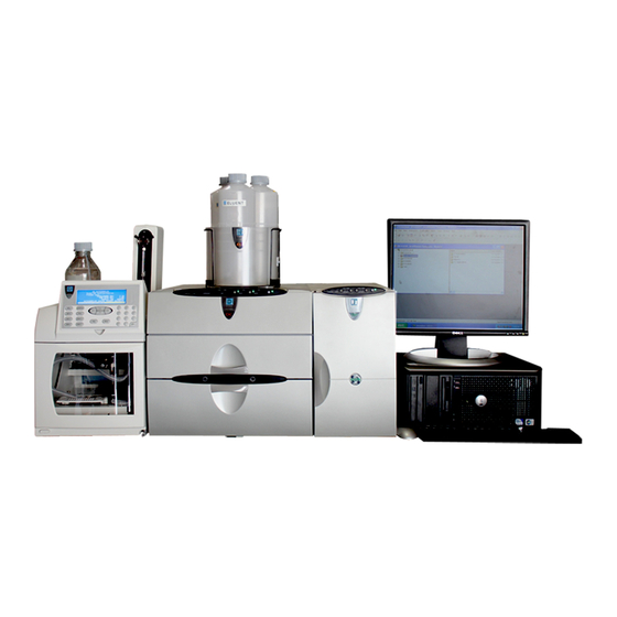
ICS-3000 Generator Detector/Chromatography AS Autosampler Module Figure 1-1. ICS-3000 System for Dual-Analysis RFIC The Dionex ICS-3000 Ion Chromatography System offers a full range of Reagent- Free IC (RFIC ) components. RFIC combines automated eluent generation ™ ™ and self-regenerating suppression to make IC easier and more powerful than ever... -
Page 18: Ics-3000 System Components
ICS-3000 System Components The table below identifies modules in the ICS-3000 product line, as well as additional products that can be added to an ICS-3000 system. Refer to the page number indicated here for a brief product overview. Product Type... - Page 19 Mass Spectrometer MSQ Plus™ (see page ICS-3000 Dual Pump (DP) and ICS-3000 Single Pump (SP) With flow rates ranging from 0.001 to 10.0 mL/min and operating pressures up to 35 MPa (5000 psi), the DP/SP is designed for both standard bore and microbore applications. The pump’s patented isokinetic pre-compression phase allows a precise, almost pulse-free flow.
- Page 20 (solenoid) valves, reaction coils, etc. The AM is installed in the upper compartment of the DC, above the detector. ICS-3000 Thermal Compartment (TC) The TC provides a temperature-controlled environment for ICS-3000 chromatography components. The TC is intended for applications that do not require conductivity or electrochemical detection.
- Page 21 1 • Introduction ICS-3000 Eluent Generator (EG) The EG generates high purity acid or base eluents online from deionized water. The EG can be configured for single- or dual-channel operation. Each channel includes: • A high precision programmable current source (power supply) •...
- Page 22 ICS-3000 Ion Chromatography System AS Autosampler (AS) The AS is a powerful, full-featured autosampler that precisely delivers from 1.0 to 99.9 µL (in 0.1 µL increments) or 100 to 1000 µL (in 1 µL increments) of sample to an injection valve. The autosampler can operate in several modes: •...
- Page 23 1 • Introduction AS40 Automated Sampler (AS40) The AS40 is a low-cost, metal-free, sample loading device designed for ion chromatography applications. The AS40 is capable of delivering between 0.2 and 5.0 mL of sample in set increments. The AS40 holds between 66 and 88 vials, depending upon the vial size in use: 0.5 mL, 5.0 mL, or a combination of both sizes.
- Page 24 ICS-3000 Ion Chromatography System MSQ Plus Mass Spectrometer The MSQ Plus is an advanced analytical instrument that includes an MS detector, vacuum pumps, and data system. When integrated with an IC system, the MSQ Plus provides the separation capability of an IC and the detection capability of a single-quadrupole MS detector.
-
Page 25: Ics-3000 System Control
1 • Introduction 1.1.2 ICS-3000 System Control The ICS-3000 system is controlled by a PC configured with Chromeleon Chromatography Management System (version 6.7 or later) or Chromeleon Xpress. The Chromeleon Chromatography Management System provides complete instrument control, data acquisition, and data provides real-time control and management. -
Page 26: Ics-3000 System Documentation
ICS-3000 Ion Chromatography System ICS-3000 System Documentation Every effort has been made to provide complete and accurate user documentation for the ICS-3000 system. The table below lists the primary sources of product information and the formats in which information is available. Source... -
Page 27: The Ics-3000 System Operator's Manual
1 • Introduction The ICS-3000 System Operator’s Manual 1.3.1 Overview The electronic version (i.e., PDF file) of the ICS-3000 system operator’s manual contains numerous hypertext links that can take you to other locations within the file. These links include: •... -
Page 28: Safety Messages And Notes
1.3.2 Safety Messages and Notes This manual contains warnings and precautionary statements that can prevent personal injury and/or damage to the ICS-3000 system when properly followed. Safety messages appear in bold type and are accompanied by icons, as shown below. - Page 29 1 • Introduction Messages d'avertissement en français Signale une situation de danger immédiat qui, si elle n'est pas évitée, entraînera des blessures graves à mortelles. Signale une situation de danger potentiel qui, si elle n'est pas évitée, pourrait entraîner des blessures graves à mortelles. Signale une situation de danger potentiel qui, si elle n'est pas évitée, pourrait entraîner des blessures mineures à...
-
Page 30: Safety And Regulatory Information
The ICS-3000 system is designed for IC (ion chromatography) and HPLC (high- performance liquid chromatography) applications and should not be used for any other purpose. Operation of an ICS-3000 module in a manner not specified by Dionex may result in personal injury. - Page 31 1 • Introduction These symbols appear on the ICS-3000 modules or on labels affixed to the modules: ˜ Alternating current Protective conductor terminal Power supply is on Power supply is off Indicates a potential hazard. Refer to this operator’s manual for an explanation of the hazard and how to proceed.
- Page 32 ICS-3000 Ion Chromatography System Doc. 065031-04 1/08...
-
Page 33: Description
DP/SP Description DP/SP Front Features A status bar on the front of the ICS-3000 Dual Pump (DP) and ICS-3000 Single Pump (SP) includes buttons for controlling certain pump functions, as well as LEDs (light emitting diodes) that indicate the status of several pump functions... - Page 34 ICS-3000 Ion Chromatography System Button/LED Label If the LED Is On If the LED Is Flashing CONNECTED The DP/SP is connected to a Does not flash. Chromeleon or Chromeleon Xpress timebase. ALARM A DP/SP-related problem has Does not flash. occurred (for example, a pressure limit was activated).
-
Page 35: Dp/Sp Interior Components
2 • DP/SP Description DP/SP Interior Components The pump’s mechanical components are located directly behind the front door of the module. Figure 2-3 shows the mechanical components of a DP that contains both a gradient pump (pump 1) and an isocratic pump (pump 2). For servicing components, the component mounting panel slides out about 5 cm (2 in) for easy access to components. -
Page 36: Pump Heads
ICS-3000 Ion Chromatography System 2.2.1 Pump Heads The DP/SP is a zero-pulsation, serial dual-piston pump with electronic compressibility compensation. Two pump heads—a primary head and a secondary head—are connected in series. Eluent passes through both pump heads in succession. The primary pump head delivers eluent at the selected flow rate, while simultaneously filling the secondary pump head. -
Page 37: Vacuum Degassing Module
2 • DP/SP Description 2.2.4 Vacuum Degassing Module The DP/SP vacuum degassing module provides continuous, online eluent degassing. Eluent quality significantly affects DP/SP performance, and vacuum degassing eluents is one way to ensure high eluent quality. Degassing helps prevent bubbles (caused by eluent outgassing) from forming in the eluent proportioning valves (gradient pump only), pump heads, and detector cell. -
Page 38: Piston Seal Wash System
The piston seal wash system is designed for use with only one of the two pumps in a DP module. When the DP is shipped from Dionex, the seal wash system is connected to pump 1 (the bottom pump). If necessary, connect the seal wash system to pump 2 (the top pump), instead. -
Page 39: Dp/Sp Flow Schematics
2 • DP/SP Description DP/SP Flow Schematics 2.3.1 Isocratic Pump Flow Schematic Figure 2-4 illustrates the liquid flow path through an isocratic pump. TO INJECTION VALVE OUTLET ELUENT CHECK VALVE PUMP PUMP HEAD HEAD INLET VACUUM CHECK VALVE DEGAS ELUENT SUPPLY ON/OFF VALVE Figure 2-4. -
Page 40: Gradient Pump Flow Schematic
ICS-3000 Ion Chromatography System 2.3.2 Gradient Pump Flow Schematic Figure 2-5 illustrates the liquid flow path through a gradient pump. STATIC MIXER TO INJECTION VALVE ELUENT ELUENT ELUENT ELUENT OUTLET CHECK VALVE PUMP PUMP HEAD HEAD INLET CHECK VALVE VACUUM... -
Page 41: Dp/Sp Rear Panel
2 • DP/SP Description DP/SP Rear Panel Figure 2-6 illustrates the rear panel of the DP/SP. Tubing Chase (2) Main Power Switch, Fuse Holder, and Power Receptacle Analog Pressure Output Digital I/O Port USB Receptacle (“B” Connectors) USB Ports (3) (“A”... - Page 42 Table 2-1 indicates the functions assigned to the connector pins. For instructions on connecting the pump to an AS40, refer to the ICS-3000 Ion Chromatography System Installation Instructions (Document No. 065032). The manual is included on the Dionex Reference Library CD-ROM (P/N 053891).
- Page 43 2 • DP/SP Description Pin Number Signal Name Signal Level Description Relay 1 Out Potential-free Common Relay 2 Out Potential-free Common Ground Ground Ground Ground Ground Ground Ground Ground ----- ----- Not used Relay 4 Out Potential-free Normally open Relay 4 Out Potential-free Common Relay 4 Out...
- Page 44 • Three USB (Universal Serial Bus) ports (“A” type connectors) are provided for connections to other ICS-3000 modules. One 1.8-m (6-ft) USB cable (P/N 960777) is provided in the ship kit (DP Ship Kit, P/N 062463; SP Ship Kit, P/N 063342).
-
Page 45: Eluent Reservoirs
Offline Vakkum-Entgasen von Eluenten. Der Behälter ist dafür nicht ausgelegt. All eluent reservoirs listed above are pressurizable. Although the DP/SP does not require pressurized reservoirs, Dionex recommends pressurizing reservoirs with helium or nitrogen under the following circumstances: • When using eluents that are sensitive to contamination. -
Page 46: Eo (Optional)
0,07 MPa aus. EO (Optional) The ICS-3000 Eluent Organizer (EO) holds eluent reservoirs in a liner that contains spills and leaks. Up to two EOs can be installed on top of the DC. Each EO accommodates up to four 1-liter or 2-liter reservoirs or up to two 4-liter reservoirs. -
Page 47: Eg Description
EG Description EG Front Features The status bar on the front of the ICS-3000 Eluent Generator (EG) includes buttons that provide control of certain EG functions, as well as LEDs that indicate the status of several EG functions (see Figure 2-7). - Page 48 ICS-3000 Ion Chromatography System Button/LED If the LED Is On Comment Label POWER Use this button for routine The main power switch is on POWER on/off control of the EG. When the the EG rear panel. power is on, this LED is lighted. To turn off the EG, press and hold this button for 2 seconds.
-
Page 49: Eg Interior Components
2 • EG Description EG Interior Components Figure 2-8 shows the EG component compartment, which is located directly behind the front door. The component mounting panel divides the compartment into two sections. In a single-channel EG, components are installed in the left section only. - Page 50 EluGen Cartridge anion exchange separations. For more information, refer to the EluGen cartridge manual. The manual is included on the Dionex Reference Library CD-ROM (P/N 053891). RFIC Eluent Degasser The RFIC Eluent Degasser (P/N 062137) contains a tubing assembly that purges the electrolysis gas from the freshly-generated eluent before it is directed to the separator column.
- Page 51 KHCO eluent. For more information about these products, refer to the EluGen cartridge manual. Cartridge manuals are included on the Dionex Reference Library CD-ROM (P/N 053891). Leak Sensor If liquid collects in the drip tray in the bottom of the EG, a leak sensor reports the leak to Chromeleon or Chromeleon Xpress, and an error message is displayed in the Audit Trail.
- Page 52 NOTE A gas separator waste tube (P/N 045460) should be connected to the EG waste line during installation. For details, refer to the ICS-3000 Ion Chromatography System Installation Instructions (Document No. 065032). Place the free end of the waste line into a waste container. To maintain an active drain, position the waste container below the level of the EG.
-
Page 53: Eg Rear Panel
2 • EG Description EG Rear Panel Figure 2-9 illustrates the rear panel of the ICS-3000 Eluent Generator (EG). Exhaust Fan Gas Vent Lines USB Receptacle (“B” Connector) USB Ports (2) (“A” Connectors) Fuse Holder, Main Power Switch, and Power... - Page 54 ICS-3000 Ion Chromatography System Fuse Holder, Main Power Switch, and Power Receptacle The fuse cartridge contains two 2-amp slow-blow fuses (P/N 954773). For instructions on how to change the fuses, see Section 9.16. The rear panel power switch is the main power switch for the EG. Turn on the main power switch before initial operation and leave it on unless instructed to turn it off (for example, before performing a service procedure).
-
Page 55: Eg Flow Schematic
Degasser inside the EG, and finally to waste. NOTE Refer to the EGC-CO Mixer manual for a flow schematic showing the components required to generate a carbonate/bicarbonate mixture. The manual is included on the Dionex Reference Library CD-ROM (P/N 053891). Doc. 065031-04 1/08... - Page 56 ICS-3000 Ion Chromatography System EGC VENT RFIC Eluent Degasser Regen Regen To Waste Eluent Eluent Inlet Outlet From pump Regen Out Port To injection valve port P (blue label) CR-TC To gas separator waste tube Regen Out Eluent In Port...
-
Page 57: Dc Description
DC Description 2.11 DC Front Features A status bar on the front of the ICS-3000 Detector/Chromatography Module (DC) (see Figure 2-12) includes buttons for controlling certain DC functions, as well as LEDs that indicate the status of several DC components and functions. - Page 58 ICS-3000 Ion Chromatography System Button/LED Label If the LED Is On If the LED Is Flashing VALVE 1 LOAD Use the Valve error. See Section 8.25 VALVE 1 VALVE 2 VALVE 2 LOAD buttons to manually switch the for troubleshooting.
- Page 59 2 • DC Description Sample Loading Ports The front of the DC has two sample loading ports (see Figure 2-12) that can be connected to injection valves installed inside the DC. A syringe is used to manually load sample through the ports. For automated sample injection, the DC can be connected to an autosampler.
-
Page 60: Dc Interior Components
Upper Compartment The upper compartment consists of two sections: • The top section houses an optional ICS-3000 Automation Manager (AM). The AM contains various components required for performing matrix elimination, large volume pre-concentration, post-column reagent addition, and other functions. See Section 2.17... - Page 61 2 • DC Description Suppressors for conductivity detection are installed in this compartment also. The following types of suppressors can be used: • SRS Self-Regenerating Suppressor (SRS 300 or ULTRA II) (2- and 4-mm) • AES Atlas Electrolytic Suppressor • MMS™...
- Page 62 ICS-3000 Ion Chromatography System Temperature Control The following temperature control zones are possible with the DC, depending on the options installed: • In the single-zone (shared) configuration, the upper and lower compartments are in the same temperature zone. The temperature can be set to between 15 and 40 °C.
-
Page 63: Dc Rear Panel
2 • DC Description NOTE A DC Temperature Calibration Kit (P/N 063782) is available. The kit includes the parts and instructions required to verify the temperature calibration of the DC upper and lower compartments and to recalibrate, if required. 2.13 DC Rear Panel Figure 2-15 illustrates the rear panel of the DC. - Page 64 ICS-3000 Ion Chromatography System Switched AC Sockets The two AC receptacles can be used to control the power to external devices. Use Chromeleon or Chromeleon Xpress to switch the power on and off. TTL inputs can also be used to control the AC sockets (see Section 2.18.4).
- Page 65 2 • DC Description External Low Pressure Valve Outputs Six outputs allow connection to externally-installed low-pressure (solenoid) valves. Low-pressure valves can be used for on/off control of liquid flow (for example, to turn flow on and off from a reagent reservoir). You control the outputs with Chromeleon or Chromeleon Xpress.
-
Page 66: Injection Valves
The following models are available: 6-port (P/N 061961) and 10-port (P/N 061962). 2.14.1 Injection Valve Operation Each ICS-3000 Ion Chromatography System injection valve has two operating positions: Load and Inject. Liquid flows through either the Load or Inject path, depending on the valve position. - Page 67 NOTE Other plumbing configurations for the 10-port valve are possible, depending on the components to be connected to the valve and the application to be run. Refer to the appropriate Dionex Application Note for more information. LOAD POSITION INJECT POSITION...
-
Page 68: Injection Valve Plumbing
(P/N 042949) is installed between ports L (1) ™ and L (4). Dionex offers sample loops in various sizes. If needed, the pre-installed 10 μL loop can be replaced with a loop that has a different sample injection volume. -
Page 69: Cd Conductivity Detector
2 • DC Description 2.15 CD Conductivity Detector One or two ICS-3000 Conductivity Detectors (CDs) can be installed in the DC. Each CD consists of a heated conductivity cell and the electronics required for collecting the conductivity data and sending it to the computer and the analog output (if installed). - Page 70 ICS-3000 Ion Chromatography System Temperature Control Temperature directly affects the conductivity of a solution. For example, laboratory heating and air conditioning systems can cause a regular slow cycling in the baseline. This, in turn, can affect the reproducibility of an analysis.
-
Page 71: Suppressor
For details about any of the suppressors, including guidelines for selecting a suppressor for your application, refer to the suppressor manuals. The manuals are on the Dionex Reference Library CD-ROM (P/N 053891). NOTE A gas separator waste tube (P/N 045460) should be... -
Page 72: System Flow Schematic For Conductivity Detection
DC for a conductivity detection application using suppression in recycle mode. For information about other suppression modes, refer to the suppressor manuals. The manuals are on the Dionex Reference Library CD-ROM (P/N 053891). COND CELL... -
Page 73: Ed Electrochemical Detector
2 • DC Description 2.16 ED Electrochemical Detector One or two ICS-3000 Electrochemical Detectors (EDs) can be installed in the DC. Each complete ED assembly consists of an amperometry cell and the detector electronics required to collect data and send it to the computer and the analog output (if installed). -
Page 74: Combination Ph-Ag/Agcl Reference Electrode
ICS-3000 Ion Chromatography System Cell Design The ED amperometry cell is a thin-layer design. Eluent flows in a thin channel parallel to the surface of a flat disk electrode. The resulting smooth flow minimizes noise. The low volume (0.25 μ... - Page 75 2 • DC Description pH–Ag/AgCl electrode also shifts by -0.059 V per pH unit, pH-dependent potential shifts at the working electrode are canceled. Correcting for pH Dependence At an eluent pH of 7, the reference potential of the entire electrode is the same as that of the Ag/AgCl half-cell.
-
Page 76: Dc Amperometric Detection
ICS-3000 Ion Chromatography System 2.16.3 DC Amperometric Detection In DC amperometry, a constant potential is applied to the working electrode. The potential can be entered into a program file (PGM) (see Figure 2-23) or on the Control panel for direct control. -
Page 77: Integrated And Pulsed Amperometric Detection
2 • DC Description 2.16.4 Integrated and Pulsed Amperometric Detection Integrated and pulsed amperometric detection are similar to DC amperometry (see Section 2.16.3) in that molecules are oxidized or reduced at the surface of an electrode. However, with these detection modes, a series of potential changes is repeated over time. - Page 78 ICS-3000 Ion Chromatography System Integrated Amperometric Detection With integrated amperometric detection (also known as IA or IPAD), current is integrated at two or more potentials (see Figure 2-25). +0.60 +0.35 Potential (Volts) -0.10 Integration -0.60 E1, E2. Analytical Potentials Time (Seconds) E3.
-
Page 79: Cyclic Voltammetry Detection
2 • DC Description 2.16.5 Cyclic Voltammetry Detection The determination of the optimum potentials to use in amperometry begins with an electrochemical technique called voltammetry, in which the current that results from oxidation or reduction reactions is measured against the voltage applied to the system. The applied voltage is changed (scanned) within preset limits. - Page 80 ICS-3000 Ion Chromatography System In this example, the potential is scanned from -0.80 to +0.60 V and then from +0.60 to -0.80 V. The total time for one waveform period is 28 s. This provides a sweep rate of 0.1 V/s as shown in the equation below.
- Page 81 2 • DC Description • The maximum waveform period is 2.0 s. However, for 2D data, because only one data point is generated per waveform period, the effective maximum length of a waveform period depends on the data collection rate (the rate at which Chromeleon collects digital data points from the detector).
- Page 82 ICS-3000 Ion Chromatography System You can use a pre-programmed waveform, without modification, or modify it for your application. You can also define a new waveform. Waveforms are defined and modified in the Waveform Editor (see Figure 2-29). Click the Edit button on the Program Wizard: ED Options page to view the Waveform Editor.
- Page 83 2 • DC Description Analytical vs. Scanning Waveforms The pre-programmed analytical waveforms supplied with Chromeleon are designed for quantitative analysis of specific compounds (alcohols, amino acids, carbohydrates, etc.). With analytical waveforms, integration occurs either while a single constant potential is being applied over time (see the example waveform in Figure 2-24) or while a series of stepped...
-
Page 84: Storing And Reprocessing Amperometry Data
ICS-3000 Ion Chromatography System 2.16.7 Storing and Reprocessing Amperometry Data NOTE Chromeleon Xpress cannot store or reprocess amperometry data. Chromeleon provides storage of both 2D and 3D pulsed amperometry and integrated amperometry data. For 2D data, Chromeleon stores the detector’s response at each waveform period’s integration interval. One integrated data point per waveform period is stored. - Page 85 2 • DC Description how to acquire 3D amperometry data, refer to the 3D Amperometry User’s Manual (Document No. 065218). Chromeleon displays and lets you reprocess the 3D data in the 3D Amperometry View window (see Figure 2-32). To open the window, double-click the sample in the Browser to open the chromatogram.
- Page 86 ICS-3000 Ion Chromatography System The raw 3D amperometry data plot can be viewed as either an Iso or a 3D (wireframe) plot. For both plot types, colors are used to represent the ranges of response values. The Iso view is the default view for the 3D raw data. This is a top down...
- Page 87 2 • DC Description of responses as well as the color mappings (see Figure 2-34). For this view, imagine you are standing in front and slightly to the left of the plot. retention time (min) Figure 2-34. 3D Amperometry Data in Chromeleon: 3D View Baseline Correction Based on the peak recognition algorithm, Chromeleon can calculate a baseline I-t plot for each data point of a peak.
- Page 88 ICS-3000 Ion Chromatography System Figure 2-35 is an example of 3D amperometry data before baseline correction is enabled. Figure 2-35. 3D Amperometry Data Before Baseline Correction Figure 2-36 shows the same data after baseline correction is enabled. Figure 2-36. 3D Amperometry Data After Baseline Correction...
-
Page 89: Automation Manager
2 • DC Description 2.17 Automation Manager The ICS-3000 Automation Manager (AM) provides a mounting location for various components used for performing matrix elimination, large volume pre- concentration, post-column reagent addition, and other functions. Each AM consists of a tray on which valves and other components are installed... -
Page 90: High-Pressure Switching Valves
ICS-3000 Ion Chromatography System In addition to the configurations described above, you can order the following components separately for installation on an AM: AM Component Part Number High-pressure valve, 6-port 061961 High-pressure valve, 10-port 061962 Low-pressure valve, 3-way 061971 Low-pressure valve, 2-way... -
Page 91: Low-Pressure Valves
2 • DC Description Valve port connections to chromatography components vary, depending on the application. Refer to Chapter 3 for the configuration schematic for your application. Valves are controlled by Chromeleon or Chromeleon Xpress (see Section 2.17.3). 2.17.2 Low-Pressure Valves Up to two low-pressure valves can be mounted on an AM. -
Page 92: High- And Low-Pressure Valve Control
ICS-3000 Ion Chromatography System 2.17.3 High- and Low-Pressure Valve Control Chromeleon or Chromeleon Xpress is used to control the high- and low- pressure valves. Commands for valve control can be included in a program (see Figure 2-41) for automated control, or the valves can be... - Page 93 2 • DC Description Figure 2-42. DC Control Panel Doc. 065031-04 1/08...
-
Page 94: Reaction Coil Heater
ICS-3000 Ion Chromatography System 2.17.4 RCH-1 Reaction Coil Heater The RCH-1 Reaction Coil Heater (P/N 061746) can hold up to two reaction coils. The heater has an operating temperature range of from 5 °C above the temperature of the upper compartment up to 80 °C. -
Page 95: I/O Option
2 • DC Description 2.18 I/O Option When the I/O option (P/N 062201) is installed, two 12-pin connector strips are on the DC rear panel. Figure 2-44 describes the functions assigned to each connector pin. Connector Description Position Pin Function Analog –... -
Page 96: I/O Option Connections
ICS-3000 Ion Chromatography System 2.18.1 I/O Option Connections 1. Locate the twisted pair of wires (P/N 043598) and 12- Position 1 position connector Locking plugs (P/N 923686) Screws (see Figure 2-45) provided with the I/O Position 12 option board. 2. For each I/O function Figure 2-45. -
Page 97: Analog Outputs
2 • DC Description 2.18.2 Analog Outputs When the I/O option is installed, two analog outputs (one for each detector) are installed on the DC rear panel (see Figure 2-15). The analog outputs supply a voltage signal proportional to the current measured by the detector cell. - Page 98 ICS-3000 Ion Chromatography System Analog Output Setting Values Description Recorder calibration Zero, Full Scale, Use this setting to calibrate a Normal recording device. Select Zero to set the output signal to zero volts. Select Full Scale to set the output signal to the selected full-scale voltage (0.01,...
- Page 99 2 • DC Description Figure 2-46. Conductivity Detector Control Panel Doc. 065031-04 1/08...
-
Page 100: Power, Relay, And Ttl Outputs
2.18.3 Power, Relay, and TTL Outputs The power, relays, and TTL outputs can be used to control functions in external devices such as an autosampler or another Dionex module. Depending on which pins are connected, the relay connection can be either normally open (N.O.) or normally closed (N.C.) (see... - Page 101 2 • DC Description You can control the power, relays, and TTL outputs from the DC Control panel in Chromeleon or Chromeleon Xpress (see Figure 2-48). Control the relays and TTLs from here Figure 2-48. DC Control Panel NOTE It is possible to change the settings for the power, relays, and TTL outputs while a Chromeleon or Chromeleon Xpress program is running.
-
Page 102: Ttl Inputs
ICS-3000 Ion Chromatography System 2.18.4 TTL Inputs When connected to a controlling device, the TTL inputs can be programmed to perform the following DC functions: • Injection valves left and right (load/inject) • AM high-pressure valves A and B (A/B) •... - Page 103 2 • DC Description 3. Select the TTL Inputs tab (see Figure 2-49). Figure 2-49. DC Server Configuration Properties: TTL Inputs 4. Select the name of the input and press the F2 key (or double-click the name). Doc. 065031-04 1/08...
- Page 104 ICS-3000 Ion Chromatography System The Device Configuration dialog box for the selected input appears. Figure 2-50. Assign TTL Input Control Functions 5. In the Control Functions list, select the check box of one or more functions to be controlled by this input. When connected to a controlling device, the device can send a signal to the input to trigger the selected functions.
- Page 105 2 • DC Description correct type. Select the input control type in the Device Configuration dialog box for each TTL input (see Figure 2-50). • Normal Edge: In normal edge operation, the negative (falling) edge of a signal turns on the function.
- Page 106 ICS-3000 Ion Chromatography System Doc. 065031-04 1/08...
-
Page 107: Tc Description
TC Description 2.19 TC Front Features A status bar on the front of the ICS-3000 Thermal Compartment (TC) includes LEDs (light emitting diodes) that indicate the status of several TC components and functions (see Figure 2-51). LOAD INJECT LOAD INJECT... - Page 108 ICS-3000 Ion Chromatography System LED Label If the LED Is On If the LED Is Flashing OVEN The TC is at its set temperature. The TC is transitioning to the set temperature. The TC is not ready for operation. If the LED is flashing and the ALARM LED is lighted, an oven error has been detected.
-
Page 109: Tc Interior Components
TC Description 2.20 TC Interior Components Figure 2-52 illustrates the interior of the TC. The components installed in your TC may vary, depending on your application. Slots for Column ID Chip Guard Column Cards (A, B, C, and D) Injection Valves Column Brackets Separator Column Temperature Stabilizer... - Page 110 ICS-3000 Ion Chromatography System Column Brackets The column brackets are installed in the TC at the factory. The TC can hold up to three columns with an inner diameter of 1 to 9 mm and a maximum length of 30 cm (11.8 in). Columns are attached to the brackets with special column clips (P/N 064786;...
-
Page 111: Tc Rear Panel
TC Description 2.21 TC Rear Panel Figure 2-53 illustrates the rear panel of the TC. Main Power Switch, Digital I/O Drain Port USB Receptacle Fuse Holder, and Connectors (2) (“B” Connector) Power Receptacle Figure 2-53. TC Rear Panel Main Power Switch, Fuse Holder, and Power Receptacle The rear panel power switch is the main power switch for the TC. - Page 112 ICS-3000 Ion Chromatography System The power supply cord is used as the main disconnect device. Make sure the socket-outlet is located near the TC and is easily accessible. Le cordon d'alimentation principal est utilisé comme dispositif principal de débranchement. Veillez à ce que la prise de base soit située/installée près du module et facilement accessible.
- Page 113 TC Description Use the 6-pin mini-DIN signal cable (P/N 6000.1004) provided in the TC Ship Kit (P/N 064789) to connect the TC to an external device. For details about the pin assignments, refer to Table 2-3. Signal Name Signal Level Core Core Label Color...
-
Page 114: Injection Valves
ICS-3000 Ion Chromatography System 2.22 Injection Valves The TC is available in the following configurations: TC Description Part Number TC with one 2-position, 6-port high-pressure injection valve 064660 TC with two 2-position, 6-port high-pressure injection valves 064661 TC with one 2-position, 6-port high-pressure injection valve and... - Page 115 TC Description • In the Inject position, sample is swept to the column for analysis. Eluent flows from the pump, through the sample loop, and on to the column, carrying the contents of the sample loop with it. Section 5.2 describes how to inject samples.
-
Page 116: Injection Valve Plumbing
25 μL PEEK sample loop (P/N 042857) is installed between ports L (1) and L (4). Dionex offers sample loops in various sizes. If needed, the pre-installed 25 μL loop can be replaced with a loop that has a different sample injection volume. -
Page 117: Column Identification (Id) System
TC Description 2.23 Column Identification (ID) System The electronic column ID system stores column-specific information on a column ID chip card (P/N 5710.1500) that is connected to a column for the column life cycle (see Figure 2-58). Column ID Chip Card Figure 2-58. -
Page 118: Gas And Humidity Sensors
ICS-3000 Ion Chromatography System 2.24 Gas and Humidity Sensors The TC contains two sensors to detect any gas or humidity that may accumulate inside the TC. When a certain concentration of gas or humidity is reached (while the door is closed), the following events occur: •... -
Page 119: Theory Of Operation
Before selecting the TC temperature, refer to the column manual for the recommended operating conditions. Column manuals are provided on the Dionex Reference Library CD-ROM (P/N 053891). The thermo-optimized design of the TC reduces the time required to equilibrate the temperature between the column and the eluent. -
Page 120: Predictive Performance
ICS-3000 Ion Chromatography System Do not touch any metal parts inside the TC while it is heating up or after it reaches the set point temperature. Wait for the compartment to cool down before servicing any parts. Ne touchez à aucune des pièces métalliques à l'intérieur du TC pendant qu'il chauffe ou après qu'il ait atteint la température de... -
Page 121: Configurations
3 • Configurations Overview This chapter provides some example component and plumbing drawings for the following ICS-3000 system configurations: ICS-3000 Configuration IC System (CD) page 106 Reagent-Free IC (RFIC) (single system) page 107 RFIC Dual System with two CDs page 108... - Page 122 ICS-3000 Ion Chromatography System To the pump inlet via the pump rear chase Eluent Pump (front view) DC (front view) Seal Wash Pump Cell In Cell Out Regen Out Eluent Out Eluent In Regen In Piston Seal Wash Separator Guard Temp.
- Page 123 3 • Configurations Pump (front view) To the pump inlet via the pump rear chase Seal Wash Pump (pump not to scale) Piston Seal Wash Deionized Water On/Off Mixer Valve To waste From the suppressor Regen Out via the DC rear chase DC (front view) (left side view) RFIC...
- Page 124 ICS-3000 Ion Chromatography System Pump (front view) To pump #2 inlet via the pump rear chase To pump #1 inlet via the pump rear chase Seal Wash Pump System #2 Mixer To waste (pump not to scale) Piston Seal Wash...
- Page 125 3 • Configurations Pump (front view) To pump #2 inlet via the pump rear chase To pump #1 inlet via the pump rear chase Seal Wash Pump System #2 Mixer Mixing Chamber To waste (pump not to scale) Piston To inject valve #2 port P (2) Seal Wash System #1...
- Page 126 ICS-3000 Ion Chromatography System To pump #2 inlet via the pump rear chase Pump (front view) To pump #1 inlet (A) via the pump rear chase Seal Wash Pump Pump #2 On/Off Mixer Valve To waste (pump not to scale)
- Page 127 3 • Configurations To pump #2 inlet via the pump rear chase Pump (front view) To pump #1 inlet (A) via the pump rear chase Injection Valve Connections Key Seal Wash Concentrator Pump To column Pump #2 Sample in Eluent in On/Off Mixer Valve...
- Page 128 ICS-3000 Ion Chromatography System To pump #2 inlet via the pump rear chase To Regen In Pump (front view) via the DC To pump #1 inlet (A) via the pump rear chase rear chase To 3-way valve #1 COM Port...
-
Page 129: Startup
4 • Startup This section is an overview of the steps required to start up the ICS-3000 system components and prepare the system to run samples. The operating parameters (flow rate, compartment temperature, suppressor current, etc.) depend on the application you plan to run. Refer to the column manual, as well as the schematics Chapter 3 of this manual, for the required operating parameters. - Page 130 1.3-cm (0.52-in) ID black gas separator waste tube (P/N 045460) in an uncapped waste container. Connect the Waste, Gas Separator line to the waste tube. NE FERMEZ PAS LE CONTENEUR DE GAZ RÉSIDUEL: Le ICS-3000 Eluent Generator (EG), le Atlas Electrolytic Suppressor, et le Self- Regenerating...
-
Page 131: Ed Amperometry Cell Operating Precautions
4 • Startup 4.1.2 ED Amperometry Cell Operating Precautions • To prevent electrode contamination: • Run only clean, filtered samples. • Prepare all eluents with high purity ASTM Type I (18 megohm-cm) filtered and deionized water. • Avoid contamination of the cell with incompatible eluents. •... - Page 132 ICS-3000 Ion Chromatography System • To help determine when the reference electrode needs regenerating or replacing, monitor the pH value displayed on the Control panel in Chromeleon or Chromeleon Xpress. • To have an alarm displayed in the Audit Trail if the pH exceeds certain values, set pH limits in Chromeleon or Chromeleon Xpress.
- Page 133 4 • Startup To set amperometry cell pH limits: You can set upper and lower pH limits in the Chromeleon or Chromeleon Xpress Program Wizard. The Audit Trail displays an alarm if the limits are exceeded. NOTE To disable the alarm, set the upper limit to 14 and the lower limit to 0.
-
Page 134: System Startup Checklist
• The Start up button on the Home tab on the ICS-3000 panel tabset starts the system components (pump, suppressor, eluent generator, CR-TC, detector, etc.). The flow rate, suppressor current, and other settings that were in effect when the system was shut down are restored. -
Page 135: Preparing Samples
Filter groundwater and wastewater samples through 0.45-micron filters before injection, unless samples were filtered after collection. A Dionex High Pressure Inline Filter (P/N 044105) is available for removing particulates down to 0.45 micron from samples. Connect the inline filter between the autosampler outlet and the sample inlet port on the injection valve. -
Page 136: Diluting Samples
Before injection, pretreat samples that may contain high concentrations of interfering substances by putting them through Dionex OnGuard ® cartridges. Refer to the installation and troubleshooting guide for the OnGuard cartridge for instructions. The guide is located on the Dionex Reference Library CD-ROM (P/N 053891). 4.3.3 Diluting Samples... - Page 137 4 • Startup • Install a cap on each vial. For an AS, make sure the septum is pushed fully into the cap and the cap is securely tightened. For an AS40, use the cap insertion tool (P/N 037987) to prevent contamination and ensure the cap is inserted to the proper depth.
- Page 138 ICS-3000 Ion Chromatography System Doc. 065031-04 1/08...
-
Page 139: Dp/Sp Startup
2. If necessary, prepare the eluent for the application. For instructions, refer to the manual for the column. Column manuals are provided on the Dionex Reference Library CD-ROM (P/N 053891). 3. Fill the reservoirs with prepared eluent or deionized water. -
Page 140: Set Up The Piston Seal Wash System
The standard piston seal wash system is designed for use with only one of the two pumps in a DP module. When the DP is shipped from Dionex, the seal wash system is connected to pump 1 (the bottom pump). If you want to connect the seal wash system to pump 2 (the top pump), follow the instructions in this section. - Page 141 4 • DP/SP Startup Seal Wash Reservoir Outlet Line Connection between pump heads Connection from peristaltic pump to secondary pump head Seal Wash Reservoir Inlet Line Figure 4-1. Piston Seal Wash Connections to Pump 1 Setting Up the Seal Wash System (All pumps) 1.
- Page 142 ICS-3000 Ion Chromatography System Tubing to Secondary Pump Lever Head Outlet Tubing from Seal Wash Reservoir Rotor Figure 4-2. Peristaltic Pump 5. If a seal wash reservoir with a drop-sensor cap is installed, connect the outlet line from the reservoir cap to the secondary pump head (see Figure 4-3).
-
Page 143: Start The Pump
The eluent line is new (empty). • The eluent line contains air. 3. To display the ICS-3000 panel tabset, follow one of the steps below: • If Chromeleon is installed, launch the application and click the Default Panel Tabset toolbar button. - Page 144 ICS-3000 Ion Chromatography System limited number of device functions can be controlled directly from this panel. You can also access the Audit Trail from here. Doc. 065031-04 1/08...
- Page 145 4 • DP/SP Startup 5. To display the pump Control panel, select the Pump tab. (The tab name varies, depending on the system configuration.) 6. Select the Flow rate required for your application under Flow Control on the Control panel. 7.
- Page 146 ICS-3000 Ion Chromatography System Enter the Minimum Pressure and Maximum Pressure values under Pressure Display on the Control panel. Setting high and low pressure limits ensures that the DP/SP will automatically stop if a system malfunction occurs. Notes • When the system includes an EG, the high pressure limit for the DP/SP is 21 MPa (3000 psi) and the low pressure limit is 1.4 MPa (200 psi).
-
Page 147: Eg Startup
EG Startup Setting the Eluent Concentration 1. In Chromeleon or Chromeleon Xpress, select the Eluent Generator tab on the ICS-3000 panel tabset. This displays the EG Control panel (see Figure 4-4). Figure 4-4. EG Control Panel 2. Under EGC Control, enter a value in the Target Concentration field. - Page 148 EG contains two EluGen cartridges operating independently on separate systems (each cartridge is linked to a different DP/SP). For details, refer to the EluGen cartridge manual. Cartridge manuals are included on the Dionex Reference Library CD-ROM (P/N 053891). EluGen Cartridge Eluent Concentration Range 0.1 to 15 mM at 0.1to 1.0 mL/min flow...
- Page 149 Note that the allowable eluent concentration for a linked cartridge is less than when the cartridge is defined as independent. For details, refer to the EluGen cartridge manual. Cartridge manuals are included on the Dionex Reference Library CD-ROM (P/N 053891). EluGen...
- Page 150 ICS-3000 Ion Chromatography System desired K /KHCO eluent mixture, the K cartridge must generate the total of the two target concentrations. For example, for a 3.50 mM K /1.00 mM KHCO eluent, set EGC_1 to 3.50 mM and EGC_2 to 1.00 mM. When eluent is being generated, the K cartridge generates 4.50 mM K...
-
Page 151: Dc Startup
DC Startup Start the DC 1. Press the button on the front of the DC. POWER 2. To display the DC Control panel, select the Detector Compartment tab (see Figure 4-5). Figure 4-5. DC Control Panel 3. Turn on all temperature control devices installed in the DC and set the desired temperatures: •... -
Page 152: Equilibrate The System And Verify Operational Readiness
Refer to the column manual for the appropriate background for your application. The column manuals are included on the Dionex Reference Library CD-ROM (P/N 053891). 2. Offset the background and zero the reading by clicking the Autozero button. -
Page 153: Tc Startup
TC Startup 4.10 Start the TC 1. Press the button on the front of the TC. POWER 2. To display the TC Control panel, select the TC tab (see Figure 4-6). Figure 4-6. TC Control Panel 3. Click the Oven on button and set the temperature required for the application. Doc. -
Page 154: Equilibrate The System And Verify Operational Readiness
ICS-3000 Ion Chromatography System 4.11 Equilibrate the System and Verify Operational Readiness NOTE Sample preparation can be performed while the system is equilibrating. 1. On the Chromeleon or Chromeleon Xpress Control panel, verify that the TC temperature is at its set point and is stable. -
Page 155: Operation
5 • Operation Overview Samples can be run manually, one at a time, or else grouped in batches and run automatically. Figure 5-1 compares the typical steps performed in manual and batch sample processing. Manual Sample Batch Sample Processing Processing Load the sample Create a program* Start data... -
Page 156: Loading Samples With An Autosampler
2. Prepare and fill the sample vials and place them in the autosampler tray or cassette. Refer to the autosampler manual for detailed instructions. Autosampler manuals are provided on the Dionex Reference Library CD- ROM (P/N 053891) 3. Use one of the following methods to load sample into the injection valve sample loop: •... -
Page 157: Loading Samples With A Syringe (Push Method)
5 • Operation 5.3.1 Loading Samples with a Syringe (Push Method) Connecting a Sample Loading Port to the Injection Valve 1. For each sample loading port to be connected, locate the following items in the DC Ship Kit (P/N 062614, dual; P/N 063408, single): •... - Page 158 ICS-3000 Ion Chromatography System 3. Remove the fitting plug from the rear of the port. 4. Cut a length of green, 0.75-mm (0.030-in) ID PEEK tubing. The tubing will be used to connect the sample loading port and the sample port on the valve.
-
Page 159: Loading Samples With A Vacuum Syringe (Pull Method)
5 • Operation 5.3.2 Loading Samples with a Vacuum Syringe (Pull Method) 1. Make sure the sample loading port on the DC front door is connected to sample port on the injection valve (see Figure 5-5). If the port S (5) is not already connected, see Section 5.3.1 for connection... -
Page 160: Example Commands For Loading And Injecting Samples
14.000 CD_1.AcqOff 5.4.2 Commands for an AS40 Autosampler A relay or TTL connection is required for Chromeleon or Chromeleon Xpress to control sample loading. Refer to Installing the ICS-3000 Ion Chromatography System (Document No. 065032) for relay connection instructions. ;Note 1 -2.300 Pump_Relay_1.Closed... -
Page 161: Commands For A Remote Inject Device
5 • Operation 5.4.3 Commands for a Remote Inject Device If you manually load the sample using a syringe (see Section 5.3), you can configure a remote inject device in the same timebase as the DC. When Chromeleon or Chromeleon Xpress runs a program and a remote inject device is configured, it waits until an inject signal is received before starting data acquisition. -
Page 162: Manual Sample Processing
ICS-3000 Ion Chromatography System Manual Sample Processing To process samples manually, select operating parameters and commands from the panel tabset. Commands are executed as soon as they are entered. 1. Load and inject the sample, using a syringe (see Section 5.3.1), vacuum... -
Page 163: Saving Manual Data
• For each sample, the sequence includes a program with commands and parameters for controlling ICS-3000 modules and acquiring sample data. To create a program, click Create Program on the Sequence Control panel. • If you are using Chromeleon, the sequence also includes a quantification method for peak identification and area determination. -
Page 164: Creating A New Sequence
ICS-3000 Ion Chromatography System 5.6.1 Creating a New Sequence Two wizards are available to help you create a new sequence: Sequence Wizard and Application Wizard. • If the program and quantification method have already been created, use the Sequence Wizard. -
Page 165: Starting Batch Sample Processing
5 • Operation Using the Application Wizard 1. Click Application Wizard on the Sequence Control panel. 2. Select a suppressor type (if used) and then select an application template from the list. NOTE Instead of selecting an application template, you can use the Virtual Column Separation Simulator. - Page 166 ICS-3000 Ion Chromatography System Doc. 065031-04 1/08...
-
Page 167: Shutdown
6 • Shutdown DP/SP Shutdown If the ICS-3000 Dual Pump (DP) or ICS-3000 Single Pump (SP) will not be operated for a period of one week or more, follow the instructions below: • Fill the pump with methanol (or a similar alcohol, such as 2-propanol or ethanol). - Page 168 ICS-3000 Ion Chromatography System Before shipping the pump: • Empty the seal wash reservoir. • Disconnect the tubing from the peristaltic pump on the component panel: press the lever to the right, remove the tubing, and release the lever (see Figure 6-1).
-
Page 169: Eg Shutdown
2. If the EG has been shut down for more than 3 to 4 days, hydrate the suppressor as instructed in the product manual. Suppressor manuals are included on the Dionex Reference Library CD-ROM (P/N 053891). 3. Let the system equilibrate for 30 to 45 minutes before collecting data. - Page 170 291). 4. Hydrate the suppressor as instructed in the product manual. Suppressor manuals are included on the Dionex Reference Library CD-ROM (P/N 053891). 5. Let the system equilibrate for 30 to 45 minutes before collecting data. Before shipping the EG:...
-
Page 171: Dc Shutdown
DC Shutdown Consumables Storage The columns, suppressors, and other consumable items used with an ICS-3000 system have various short- and long-term storage requirements. Refer to the manuals for the individual products for instructions. These manuals are provided on the Dionex Reference Library CD-ROM (P/N 053891). - Page 172 ICS-3000 Ion Chromatography System 4. Insert the electrode into the cap and screw on the cap (see Figure 6-2). 5. Make sure there is no air bubble in the cap. Add more KCl solution if needed. Storage Cap Figure 6-2. Reference Electrode in Storage Cap...
-
Page 173: Tc Shutdown
TC Shutdown Consumables Storage The columns and other consumable items used with an ICS-3000 system have various short- and long-term storage requirements. Refer to the manuals for the individual products for instructions. These manuals are provided on the Dionex Reference Library CD-ROM (P/N 053891). - Page 174 ICS-3000 Ion Chromatography System Doc. 065031-04 1/08...
-
Page 175: Maintenance
7 • Maintenance This section describes routine maintenance procedures for the ICS-3000 system that users may perform. All other maintenance procedures must be performed by Dionex personnel. For information about maintenance procedures for the EluGen cartridge, CR-TC trap column, or suppressor, refer to the appropriate product manual. These manuals are included on the Dionex Reference Library CD-ROM (P/N 053891). -
Page 176: Periodic Maintenance
Preventive Maintenance Kits contain all the required parts for these procedures. DP Preventive Maintenance Kit (P/N 061794) SP Preventive Maintenance Kit (P/N 061795) DC/TC Preventive Maintenance Kit (P/N 061796) NOTE Dionex does not offer a Preventive Maintenance Kit for the EG. Doc. 065031-04 1/08... -
Page 177: Dp/Sp Routine Maintenance
DP/SP Routine Maintenance This section describes routine maintenance procedures for the ICS-3000 Dual Pump (DP) or ICS-3000 Single Pump (SP) that users may perform. All other maintenance procedures must be performed by Dionex personnel. DP/SP Daily Maintenance • Check for leaks at the following locations: the eluent proportioning valves (gradient pump only), vacuum degas chambers, and eluent reservoirs. -
Page 178: Dp/Sp Periodic Maintenance
Replace piston seals every 6 to 12 months (see Section 9.5). DP/SP Annual Maintenance • Dionex recommends performing preventive maintenance annually. The following kits are available: DP Preventive Maintenance Kit (P/N 061794) SP Preventive Maintenance Kit (P/N 061795) Doc. 065031-04 1/08... -
Page 179: Eg Routine Maintenance
EG Routine Maintenance This section describes routine maintenance procedures for the ICS-3000 Eluent Generator (EG) that users may perform. All other maintenance procedures must be performed by Dionex personnel. For information about maintenance procedures for the EluGen cartridge, CR-TC trap column, or suppressor, refer to the appropriate product manual. These manuals are included on the Dionex Reference Library CD-ROM (P/N 053891). - Page 180 ICS-3000 Ion Chromatography System Doc. 065031-04 1/08...
-
Page 181: Dc Routine Maintenance
7.11 DC Periodic Maintenance • Calibrate the CD cell (every 6 months). • Inspect the door seal for signs of damage. A defective seal impairs the performance of the instrument. If the seal is defective, contact Dionex Technical Support. Doc. 065031-04 1/08... -
Page 182: Dc Annual Maintenance
ICS-3000 Ion Chromatography System 7.12 DC Annual Maintenance Dionex recommends performing preventive maintenance annually. A DC/TC Preventive Maintenance Kit (P/N 061796) is available. Doc. 065031-04 1/08... -
Page 183: Tc Routine Maintenance
TC Routine Maintenance This section describes routine maintenance procedures for the ICS-3000 Thermal Compartment (TC) that users may perform. All other maintenance procedures must be performed by Dionex personnel. 7.13 TC Daily Maintenance • Check the TC components for leaks or spills. Wipe up spills. Isolate and... -
Page 184: Tc Periodic Maintenance
(158 °F). Remove all columns from the TC before beginning the maintenance procedure above. • Inspect the door seal for signs of damage. A defective seal impairs the performance of the instrument. If the seal is defective, contact Dionex Technical Support. 7.16 TC Annual Maintenance •... -
Page 185: Troubleshooting
8 • Troubleshooting This chapter is a guide to troubleshooting minor issues that may arise during operation of the ICS-3000 system. Turn to the section of this chapter that best describes the operating problem or symptom that has been observed. Each section lists possible causes of the problem or symptom in order of probability. -
Page 186: Dp/Sp Error Messages
ICS-3000 Ion Chromatography System 8.1.1 DP/SP Error Messages The table below lists the most frequently observed DP/SP-related error messages and their default severity levels. For troubleshooting assistance, refer to the page indicated in the table. DP/SP-Related Audit Trail Error Message... -
Page 187: Eg Error Messages
8 • Troubleshooting DP/SP-Related Audit Trail Error Message Default Severity Level This function cannot be adjusted by the user. Abort page 196 Upper pressure limit exceeded. Abort page 196 8.1.2 EG Error Messages The table below lists the EG-related error messages and their default severity levels. -
Page 188: Dc Error Messages
ICS-3000 Ion Chromatography System 8.1.3 DC Error Messages The table below lists the DC-related error messages and their default severity levels. For troubleshooting assistance, refer to the page indicated in the table. DC-Related Audit Trail Error Message Default Severity Level CD cell 1 option disconnected. -
Page 189: Tc Error Messages
8 • Troubleshooting DC-Related Audit Trail Error Message Default Severity Level Suppressor 1 open circuit. Abort page 221 Suppressor 2 open circuit. Upper door opened. Warning page 221 8.1.4 TC Error Messages The table below lists the TC-related error messages and their default severity levels. - Page 190 ICS-3000 Ion Chromatography System TC-Related Audit Trail Error Message Default Severity Level Can't use device “x” as a source of the column pressure. Error page 231 Please check the property “y” for a valid device name. The device must have the “Pressure” property available.
- Page 191 8 • Troubleshooting TC-Related Audit Trail Error Message Default Severity Level Gas leak detected. Error page 238 Humidity leak detected. Error page 238 Illegal parameter. Abort page 238 Invalid date/time format. Either use “DD MMM YYYY” or Error page 239 “current [ + [Nyear[s]] [Nmonth[s]] [Nday[s]]].”...
- Page 192 ICS-3000 Ion Chromatography System TC-Related Audit Trail Error Message Default Severity Level Properties cannot be changed—there is no card in the Error page 244 card reader. Raw data file x cannot be created. Warning page 244 Raw data file x cannot be created. Continuing with...
- Page 193 8 • Troubleshooting TC-Related Audit Trail Error Message Default Severity Level The upper limit must be higher than the lower limit. Error page 249 The Warning threshold must be higher than the Limit Error page 249 threshold. The Warning threshold must be lower than the Limit Error page 249 threshold.
-
Page 194: Noisy Baseline
ICS-3000 Ion Chromatography System Noisy Baseline • Eluent is contaminated 1. Clean all eluent reservoirs thoroughly (inside and out) with ASTM Type I (18 megohm-cm) filtered and deionized water and dry with clean, particulate-free air. If a reservoir still appears dirty, or if there is a slimy... - Page 195 Section 9.23). • Inappropriate suppressor operating conditions Refer to the suppressor manual for the correct operating conditions. Suppressor manuals are included on the Dionex Reference Library CD-ROM (P/N 053891). • Temperature compensation setting not optimized Optimize the selected setting (see Section 2.15).
- Page 196 ICS-3000 Ion Chromatography System Noisy Baseline: ED Only • (DC Amperometry and Integrated Amperometry modes) Air bubbles trapped inside cell While wearing gloves and eye protection and with the pump running and all plumbing connected, generate a slight temporary backpressure by putting your finger over the end of the cell outlet tubing for 2 to 3 seconds.
-
Page 197: Poor Retention Time Reproducibility
8 • Troubleshooting 2. Air bubbles may be trapped inside the cell. While wearing gloves and eye protection, generate a slight temporary backpressure by putting your finger over the end of the cell outlet tubing for 2 to 3 seconds. Repeat 2 or 3 times. - Page 198 ICS-3000 Ion Chromatography System • Inoperative eluent proportioning valve (gradient pump only) The proportioning valve assembly should be replaced. Contact Dionex for assistance. • Inoperative check valves Replace the check valve cartridges (see Section 9.4). • Insufficient mixing (gradient pump only) The static mixer may be dirty or contaminated.
-
Page 199: Peak Retention Times Are Too Early
DP/SP flow rate is too low Increase the DP/SP flow rate. • Inoperative eluent proportioning valve (gradient pump only) The proportioning valve assembly should be replaced. Contact Dionex for assistance. Peak Retention Times Are Too Late • Eluent concentration setting is too low The correct eluent concentration setting depends on several factors (the flow rate, EluGen cartridge type, etc.). - Page 200 ICS-3000 Ion Chromatography System • Injection valve is not actuating or the sample loop is plugged 1. Test the valve by manually switching the position from the Detector/Chromatography tab on the panel tabset. 2. Check the sample loop for blockage. Clean or replace the loop if needed.
-
Page 201: Tailing Peaks
8 • Troubleshooting ED Only • Cell is off Turn on the cell from the Control panel in Chromeleon or Chromeleon Xpress. Tailing Peaks • Excess tubing void volumes Check tubing connections for void volumes • (CD) Long tubing lengths connecting Minimize all tubing lengths between the injection valve and the detector. -
Page 202: High System Backpressure
EluGen cartridge is the source of the high backpressure, replace the outlet frit as instructed in the EluGen cartridge manual. The manual is on the Dionex Reference Library CD-ROM (P/N 053891). 3. If the restriction has caused such high pressure that the system cannot be... -
Page 203: High Background
Background not suppressed by suppressor Verify that the suppressor is turned on and the current is set to the correct value. Refer to the suppressor manual for additional troubleshooting guidance. Suppressor manuals are included on the Dionex Reference Library CD-ROM (P/N 053891). •... - Page 204 Verify that the length and potential of the integration interval is correct (refer to the column manual for the settings required for your application). Column manuals are included on the Dionex Reference Library CD-ROM (P/N 053891). •...
-
Page 205: Dp/Sp Troubleshooting
If this error occurs, the tubing between the pump heads may be blocked or the fitting may be overtightened. To troubleshoot: Inspect the tubing for blockage or crimping and replace if needed. Be careful to not overtighten the fitting. If the message appears again, contact Dionex for assistance. Camshaft index too early. -or- Camshaft index too late. - Page 206 This error is caused by an internal error in the pump drive mechanism. To troubleshoot: Turn off the DP/SP power for 30 seconds and then turn it on again. If the error message appears again, contact Dionex for assistance. Degasser malfunction. The vacuum degassing module monitors the vacuum system continuously. If a a problem is detected, this error occurs.
- Page 207 8 • DP/SP Troubleshooting Invalid flow value. This error occurs if you enter an invalid value for the DP/SP flow rate in Chromeleon or Chromeleon Xpress. To troubleshoot: Select a flow rate within the DP/SP flow rate range (0.001 to 10.0 mL/min). Leak detected.
- Page 208 To troubleshoot: Turn off the DP/SP power for 30 seconds, and then turn on the power again. If the error message appears again, contact Dionex for assistance. Motor position error. The motor is overloaded. This error occurs if the pump motor is overloaded.
- Page 209 8 • DP/SP Troubleshooting Pressure fallen below lower limit. This error occurs if the DP/SP pressure falls below the low pressure limit specified in Chromeleon or Chromeleon Xpress. To troubleshoot: 1. The eluent supply may be depleted. Refill any empty eluent reservoirs. 2.
- Page 210 ICS-3000 Ion Chromatography System Relay 4 is configured for inject synchronization. Please change pump configuration. This error occurs if you attempt to use relay 4 as a standard relay in a Chromeleon or Chromeleon Xpress program, although the relay has been set to synchronize the gradient with the autosampler sample injection.
- Page 211 If the column is the source of the high backpressure, clean the column. (Refer to the column manual provided on the Dionex Reference Library CD-ROM (P/N 053891) for instructions.) If this does not eliminate the problem, replace the column.
- Page 212 If the column is the source of the high backpressure, clean the column. (Refer to the column manual provided on the Dionex Reference Library CD-ROM (P/N 053891) for instructions.) If this does not eliminate the problem, replace the column.
-
Page 213: Dp/Sp Does Not Start
8 • DP/SP Troubleshooting blockage (i.e., the rotor seal or stator may need to be replaced). Contact Dionex for assistance. 8.13 DP/SP Does Not Start • Power is off Check that the main power switch on the DP/SP rear panel is turned on. -
Page 214: Dp/Sp Stops
ICS-3000 Ion Chromatography System 8.14 DP/SP Stops • Program (or other remote input) instructed the pump to stop If no error message is displayed in the Audit Trail, the DP/SP was probably instructed to stop by the Chromeleon or Chromeleon Xpress program, the computer, or other remote signal source. -
Page 215: Dp/Sp Liquid Leaks/Leak Alarm
3. Observe a run to see whether the high pressure limit is triggered when sample is injected; if it is, the injection valve may be causing a blockage (i.e., the rotor seal or stator may need to be replaced). Contact Dionex for assistance. - Page 216 (see Section 9.8). If leaks occurs when the priming valve knob is closed, either the pump head or the knob is damaged and should be replaced. Contact Dionex for assistance. • Excessive system backpressure...
-
Page 217: Vacuum Degassing Module Low Vacuum
• Electrical connections incorrectly installed There may be a problem with the connections from the vacuum degassing module to the CPU board. Contact Dionex for assistance. NOTE The ICS-3000 Ion Chromatography System electronics components cannot be serviced by the user. - Page 218 ICS-3000 Ion Chromatography System Doc. 065031-04 1/08...
-
Page 219: Eg Troubleshooting
1. Check the CR-TC cable connection to the electrical bulkhead (see Figure 2-8). 2. Refer to Section 8.23 to determine why liquid flow stopped. 3. If the error message appears again, contact Dionex for assistance. The CR-TC control electronics may have malfunctioned. NOTE The ICS-3000 Chromatography System electronics components cannot be serviced by the user. - Page 220 To troubleshoot: 1. Connect the EluGen cartridge cable connection to the electrical bulkhead (see Figure 2-8). 2. If the error message appears again, contact Dionex for assistance. The EluGen cartridge control electronics may have malfunctioned. NOTE The ICS-3000 Chromatography System electronics components cannot be serviced by the user.
- Page 221 8 • EG Troubleshooting EG1 invalid flow. -or- EG2 invalid flow. This error occurs if the flow rate is set to a value the EG does not support. The DP/SP flow rate range is 0.001 to 10.0 mL/min; however, when an EG is installed, the allowed range is 0.01 to 3.00 mL/min.
- Page 222 2. Refer to Section 8.23 to determine why there is no flow. 3. If the error message appears again, contact Dionex for assistance. The cartridge control electronics may have malfunctioned. NOTE The ICS-3000 Ion Chromatography System electronics components cannot be serviced by the user.
-
Page 223: Eg Alarm Led Is Lighted
8 • EG Troubleshooting 3. If the error message appears again, contact Dionex for assistance. The EluGen cartridge control electronics may have malfunctioned. NOTE The ICS-3000 Ion Chromatography System electronics components cannot be serviced by the user. Leak sensor wet. -
Page 224: Eg Power Led Fails To Light
Replace the EluGen cartridge (see Section 9.12). • Electrical error The EG current and/or voltage may have become unstable. Contact Dionex for assistance. NOTE The ICS-3000 Ion Chromatography System electronics components cannot be serviced by the user. 8.21 EG POWER LED Fails to Light •... -
Page 225: No Flow
8 • EG Troubleshooting • EluGen cartridge leaks Replace the EluGen cartridge (see Section 9.12). • RFIC Eluent Degasser leaks Replace the RFIC Eluent Degasser (see Section 9.14). 8.23 No Flow • DP/SP power is off Turning off the DP/SP automatically turns off the EG and the suppressor. Current to the CR-TC is automatically turned on and off when the EG power is turned on and off. -
Page 226: Eg Stops Operation
To prevent damage to the EluGen cartridges, the DP/SP automatically turns off electrical power to the cartridge when excessive current or voltage is detected. Contact Dionex for assistance. NOTE The ICS-3000 Ion Chromatography System electronics components cannot be serviced by the user. •... - Page 227 Check that the wall outlet has power. 4. Check the USB connections. The EG should be connected to the DP/SP (or other ICS-3000 module) via a USB cable (P/N 960777). In addition, one module in the system must be connected to the PC on which Chromeleon or Chromeleon Xpress is installed.
- Page 228 ICS-3000 Ion Chromatography System Doc. 065031-04 1/08...
-
Page 229: Dc Troubleshooting
(see Figure 8-3) to make certain the connector is securely connected. 2. If the error persists, there may be a problem in the detector electronics. Contact Dionex for assistance. NOTE The ICS-3000 Chromatography System electronics components cannot be serviced by the user. - Page 230 CD cell 2 over safe temperature. This error occurs when the temperature of the specified conductivity detector is higher than the maximum allowed. This error may occur if the ICS-3000 Ion Chromatography System is operating in an environment in which the temperature is greater than 40 °C (104 °F).
- Page 231 Compartment over safe temperature. This error occurs when the temperature of the DC lower compartment is higher than the maximum allowed. This error may occur if the ICS-3000 Ion Chromatography System is operating in an environment in which the temperature is greater than 40 °C (104 °F).
- Page 232 Push here to ensure the detector’s electrical connection is secure. Figure 8-4. Electrochemical Detector Connection 2. If the error appears again, contact Dionex for assistance. The detector electronics may have malfunctioned. NOTE The ICS-3000 Ion Chromatography System electronics components cannot be serviced by the user.
- Page 233 8 • DC Troubleshooting High pressure valve 1 error. -or- High pressure valve 2 error. -or- High pressure valve 3 error. -or- High pressure valve 4 error. This error occurs if a high-pressure valve fails to switch position within 1 second of being toggled. The high-pressure valves are the 6- or 10-port valves installed in either the DC lower (see Figure 8-5) or upper compartment...
- Page 234 To troubleshoot: 1. Verify that the door is fully closed. 2. Check for—and remove—any obstruction. 3. If the door is fully closed and the error persists, contact Dionex for assistance. Lower leak sensor wet. The leak sensor is installed in the drip tray at the bottom of the column...
- Page 235 Reaction coil over safe temperature. This error occurs when the temperature of the DC upper compartment is higher than the maximum allowed. This error may occur if the ICS-3000 Ion Chromatography System is operating in an environment in which the temperature is greater than 40 °C (104 °F).
- Page 236 ICS-3000 Ion Chromatography System 3. If you suspect a malfunction in the suppressor controller, contact Dionex for assistance. NOTE The ICS-3000 Ion Chromatography System electronics components cannot be serviced by the user. Suppressor 1 over-power. -or- Suppressor 2 over-power. This error appears when, in order to maintain the selected current, the ICS- 3000 Ion Chromatography System is required to apply a higher voltage than the suppressor can support.
-
Page 237: Liquid Leaks From Dc Components
To troubleshoot: 1. Verify that the door is fully closed. 2. Check for—and remove—any obstruction. 3. If the door is fully closed and the error persists, contact Dionex for assistance. 8.26 Liquid Leaks from DC Components •... -
Page 238: Valve Button Not Working
Dionex for assistance. • Leaking suppressor Refer to the suppressor manual for troubleshooting procedures. Suppressor manuals are included on the Dionex Reference Library CD-ROM (P/N 053891). 8.27 VALVE Button Not Working buttons on the front of the DC must be enabled in... -
Page 239: Amperometry Cell Troubleshooting
8 • DC Troubleshooting 8.28 Amperometry Cell Troubleshooting 8.28.1 Amperometry Cell pH Readout Always 7.0 The pH reading is displayed on the Chromeleon or Chromeleon Xpress EC Detector Control panel. • Disconnected reference electrode Verify that the reference electrode cable is securely connected (see Figure 8-7). -
Page 240: Cannot Set Amperometry Cell Ph Readout To 7.0
ICS-3000 Ion Chromatography System 8.28.2 Cannot Set Amperometry Cell pH Readout to 7.0 The pH reading is displayed on the Chromeleon or Chromeleon Xpress EC Detector Control panel. • Inaccurate calibration buffer Use a pH meter to check the pH of the buffer. -
Page 241: No Amperometry Cell Ph Readout Or Intermittent Readout
8 • DC Troubleshooting 3. If soaking does not fix the problem, replace the electrode (see Section 9.24.4). 8.28.4 No Amperometry Cell pH Readout or Intermittent Readout The pH reading is displayed on the Chromeleon or Chromeleon Xpress EC Detector Control panel. •... -
Page 242: Shift In Ag/Agcl Reference Potential
ICS-3000 Ion Chromatography System 8.28.6 Shift in Ag/AgCl Reference Potential • Faulty reference electrode A shift in reference potential causes a shift in the effective potential applied to the working electrode. For example, when using an electrode with a shift of 50 mV, an applied potential of 0.1 V, is equivalent to an applied potential of 0.15 V for a new reference... -
Page 243: Tc Troubleshooting
TC Troubleshooting 8.29 Troubleshooting TC Error Messages If any of the following alarm conditions occurs, a message is displayed in the Chromeleon or Chromeleon Xpress Audit Trail. AcqOff without previous AcqOn. This error occurs if the Chromeleon or Chromeleon Xpress program contains an AcqOff command, but no AcqOn command. - Page 244 ICS-3000 Ion Chromatography System All samples scheduled for run on timebases x need to specify the same value for property (nominal) Temperature. -or- All samples scheduled for run on timebases x need to specify the same value for property TempCtrl.
- Page 245 Operation of the TC requires the appropriate version of Chromeleon or Chromeleon Xpress plus a Timebase Class 1 license. This error occurs if you attempt to start data acquisition when these requirements are not met. To troubleshoot: Contact Dionex to obtain the appropriate software version and/license. Doc. 065031-04 1/08...
- Page 246 Open to begin the download. Audit Trail messages will inform you of the status of the download. 3. If the error occurs again, contact Dionex for assistance. The firmware cannot be serviced by the user. Doc. 065031-04 1/08...
- Page 247 TC Troubleshooting Can't use device “x” as a source of the column pressure. Please check the property “SystemPressure” for a valid device name. The device must have the “Pressure” property available. -or- Can't use device “x” as a source of the column pressure. Please check the property “y”...
- Page 248 To troubleshoot: 1. Check the USB connections. 2. Check the connection from the TC to the power supply. 3. If you cannot identify the cause of the error, contact Dionex for assistance. Communication time-out. This error occurs if a TC firmware (Moduleware) command is not executed within the time allotted for its completion.
- Page 249 TC Troubleshooting Configuration doesn’t match. X not installed. -or- Configuration mismatch (x - CM uses y, Column Compartment uses z). Please use the Server Configuration program to check the installation. This error occurs if there is a discrepancy between the TC properties and the actual configuration.
- Page 250 2. On the Advanced tab page in the Server Configuration dialog box, enter a new value (in seconds) in the Buffer field and click OK. If the error occurs again, contact Dionex for assistance. Device control feature is not available! Please check key code and CM Features (see “About Chromeleon...”...
- Page 251 Chromeleon server or with the power supply. To troubleshoot: 1. Check the USB connections. 2. Check the connection from the TC to the power supply. 3. If you cannot identify the cause of the error, contact Dionex for assistance. Doc. 065031-04 1/08...
- Page 252 To troubleshoot: When the chip card is properly installed, the Dionex logo on the card faces up and the LED on the memory slot is green. If this error occurs when the chip card is properly installed, it indicates that the card is defective and should be...
- Page 253 This error occurs if, during a firmware (Moduleware) download, the new firmware cannot be programmed into memory. To troubleshoot: Flash memory cannot be serviced by the user. Contact Dionex for assistance. Executing this command will reset associated counter values stored in the module.
- Page 254 ICS-3000 Ion Chromatography System Gas leak detected. This error occurs if the gas sensor detects an increased concentration of gas inside the TC. To troubleshoot: 1. Find and eliminate the leak. 2. On the TC Control panel, click the Clear Alarm button.
- Page 255 TC Troubleshooting Invalid date/time format. Either use “DD MMM YYYY” or “current [ + [Nyear[s]] [Nmonth[s]] [Nday[s]]].” Examples: “31 Dec 1999,” “current + 1 year 6 months.” This error occurs if you enter the date associated with an event in an invalid format.
- Page 256 Qualification.GracePeriod property determines for how many days after the due date you can continue using the TC without performing the qualification. To troubleshoot: Contact Dionex to schedule an Operational Qualification and Performance Qualification. Next service of this module is due in x day(s) (due date is [date]).
- Page 257 PC on which Chromeleon or Chromeleon Xpress is installed. To troubleshoot: 1. Check the USB connections. 2. Check the connection from the TC to the power supply. 3. If you cannot identify the cause of the error, contact Dionex for assistance. Doc. 065031-04 1/08...
- Page 258 This error occurs if you select a TC temperature setting above 70 °C (158 °F). To troubleshoot: Refer to the column manual for the recommended operating conditions. Column manuals are provided on the Dionex Reference Library CD-ROM (P/N 053891). Parameter x value exceeded its allowed range. Set to closest valid value x.
- Page 259 CardState command. If the status is BusBlocked, remove the card from the card slot and reinsert it. When the card is properly installed, the Dionex logo on the card faces up and the LED on the memory slot is green.
- Page 260 1. Verify that the door is fully closed. 2. If the door is not fully closed, check for—and remove—any obstruction. 3. If the door is fully closed but the error persists, contact Dionex for assistance. Properties cannot be changed—there is no card in the card reader.
- Page 261 PC on which Chromeleon or Chromeleon Xpress is installed. To troubleshoot: 1. Check the USB connections. 2. Check the connection from the TC to the power supply. 3. If you cannot identify the cause of the error, contact Dionex for assistance. Doc. 065031-04 1/08...
- Page 262 1. Verify that the door is fully closed. 2. If the door is not fully closed, check for—and remove—any obstruction. 3. If the door is fully closed but the error persists, contact Dionex for assistance. The counter [name] (value: x) has exceeded its limit (y).
- Page 263 TC Troubleshooting The injections limit for the column has been exceeded. -or- The injections limit will be exceeded for the column x. Chromeleon and Chromeleon Xpress monitor the number of injections done with each column and display an appropriate message (shown above) at the following times: when the injections limit is about to be exceeded or has been exceeded.
- Page 264 ICS-3000 Ion Chromatography System The oven is not fully operable yet. Check the values of “Standby,” “Ready,” “Door,” and “CardState.” Each time the TC power is turned on, the firmware (Moduleware) runs a series of self-diagnostics in which the status of the main components is checked.
- Page 265 TC Troubleshooting The upper limit must be higher than the lower limit. This error occurs if the value entered for a parameter’s upper limit (for example, TC_Temp.Signal.UpperLimit) is less than the lower limit for the parameter. To troubleshoot: Increase the value of the upper limit setting. The Warning threshold must be higher than the Limit threshold.
- Page 266 ICS-3000 Ion Chromatography System There was already an AcqOff command for this channel before. -or- There was already an AcqOn command for this channel before. -or- Two AcqOn commands for the same channel. The second chromatogram will overwrite the first.
- Page 267 This error occurs if Chromeleon or Chromeleon Xpress does not recognize error code sent by the TC firmware (Moduleware). To troubleshoot: The firmware cannot be serviced by the user. Contact Dionex for assistance. Unknown format of the card data. This error occurs if Chromeleon or Chromeleon Xpress does not recognize the format of data stored on the column ID chip card.
- Page 268 ICS-3000 Ion Chromatography System You do not have the privilege to approve the module's qualification. You do not have the privilege to change the performance limits. You do not have the privilege to change the qualification intervals. In controlled environments, users are not allowed to perform certain operations unless they have been granted the appropriate privileges.
-
Page 269: Tc Alarm Led Is Lighted
Clear Alarm button on the TC Control panel. If the LED is flashing, a mechanical component in the TC has failed. OVEN These parts are not user-serviceable. Contact Dionex for assistance. 8.31 Liquid Leaks from TC Components • Leaking fitting Locate the source of the leak. -
Page 270: Tc Temperature Does Not Increase
• Front door not closed Verify that the TC door is fully closed. If it is, check the door seal for signs of damage. If the seal is damaged, contact Dionex for assistance. • Column tubing connections incorrectly oriented Column tubing connections that are incorrectly oriented can open a small path for ambient air into the TC. -
Page 271: Tc Temperature Stabilizer Not Operating Properly
For detailed instructions, refer to the ICS-3000 Ion Chromatography System Installation Instructions (Document No. 065032). • TC calibration is incorrect The TC cannot be calibrated by the user. Contact Dionex for assistance. • Defective temperature stabilizer Replace the temperature stabilizer (standard bore, P/N 064548; microbore, P/N 064650). - Page 272 ICS-3000 Ion Chromatography System Doc. 065031-04 1/08...
-
Page 273: Service
9 • Service This chapter describes ICS-3000 Ion Chromatography System service and repair procedures that users may perform. All procedures not included here, including electronics-related repair procedures, must be performed by Dionex personnel. For assistance, contact Dionex Technical Support. In the U.S., call 1-800-346- 6390. -
Page 274: Cleaning Eluent Reservoirs
Use double-cone 10-32 ferrule fittings (P/N 043276) and 10-32 bolts (P/N 043275) for all other tubing connections. For tightening requirements, refer to Installation of Dionex Liquid Line Fittings (Document No. 031432). The manual is on the Dionex Reference Library CD-ROM (P/N 053891). -
Page 275: Priming The Dp/Sp
Chromeleon Xpress, refer to Section 9.3.2. Although a 10 cc syringe (P/N 054578) can be used with either priming procedure, Dionex recommends using a syringe only if eluent lines are 100% empty or if the pump is dry. 9.3.1 Priming with the... - Page 276 ICS-3000 Ion Chromatography System 4. Press ) on the front of the DP/SP. PUMP PRIME 1 PUMP PRIME 2 The pump will begin pumping at approximately 6.0 mL/min. 5. Continue priming the pump until all air and previous eluents are purged and no air bubbles can be seen exiting the waste line.
-
Page 277: Priming From The Control Panel
9 • DP/SP Service 9.3.2 Priming from the Control Panel 1. Gradient pump only: Set the channel to be primed (A, B, C, or D) to 100% on the pump Control panel in Chromeleon or Chromeleon Xpress. 2. Under Prime Control on the Control panel: a. -
Page 278: Replacing The Check Valves
ICS-3000 Ion Chromatography System NOTE After starting the pump, wait at least 5 minutes (longer for flow rates below 1.0 mL/min) before beginning an analysis. This allows the DP/SP Moduleware to stabilize the flow rate. Replacing the Check Valves A dirty check valve causes erratic flow rates and pressures; in addition, it may cause the pump to lose prime and/or be difficult to reprime. - Page 279 9 • DP/SP Service 6. The check valves are installed in the primary pump head (see Figure 9-2). Outlet Check Valve Inlet Check Valve Figure 9-2. DP/SP Check Valve Connections 7. Disconnect the tubing connections from the inlet and outlet check valves. 8.
- Page 280 ICS-3000 Ion Chromatography System 10. Inspect the new inlet check valve assembly (P/N 045722) to verify that Inlet Check Valve: Outlet Check Valve: 1/4-28 Port 10-32 Port the double-hole end of the cartridge (see Figure 9-3) is visible. If the double-hole end is not visible, remove the cartridge from the housing and install it correctly.
-
Page 281: Replacing A Piston Seal
9 • DP/SP Service 16. Select the Connected check box on the Control panel to reconnect the pump to the software. 17. Click Motor on the Control panel to start the pump flow. Replacing a Piston Seal A defective piston seal allows leakage past the piston. This may cause unstable flow rates and baseline noise;... - Page 282 ICS-3000 Ion Chromatography System 4. Use the handles on the component mounting panel to pull the panel forward until it reaches the stop. NOTE On newer pumps, three red Phillips screws are installed on the component mounting panel before shipment from the factory. If the mounting panel does not move freely, make sure these screws have been removed.
- Page 283 9 • DP/SP Service Outlet Check Valve Assembly (P/N 045721; includes check valve body and cartridge) Main Piston Seal (P/N 064946) Primary Pump Head Seal Wash Body (P/N 062083) (P/N 062064) Piston Seal Wash Seal Inlet Check Valve Assembly (P/N 063382) (P/N 045722;...
-
Page 284: Cleaning The Piston
ICS-3000 Ion Chromatography System 9.5.2 Cleaning the Piston 1. Place the piston in a beaker containing ASTM Type I (18 megohm-cm) filtered and deionized water or methanol and sonicate for several minutes. 2. After cleaning, rinse the piston thoroughly with ASTM Type I (18 megohm-cm) filtered and deionized water and dry it with a lint- free paper towel. -
Page 285: Removing The Piston Seal Wash Seal
9 • DP/SP Service 9.5.4 Removing the Piston Seal Wash Seal 1. Remove the O-ring (P/N 040695) from the seal wash body. 2. Follow these steps to remove the piston seal wash seal (P/N 063382) from the seal wash body: a. -
Page 286: Reinstalling The Piston And Pump Head
ICS-3000 Ion Chromatography System e. The seal wash seal is now partially installed. To complete the seal installation, place the retainer in the seal wash body and use the large flat-blade screwdriver to tighten the retainer. Place the new O-ring (P/N 040695) on the seal wash body. -
Page 287: Replacing The Piston
9 • DP/SP Service with the pump head. Then, tighten the screws another one-quarter to one-half turn, one-eighth of a turn at a time. 4. Reconnect all tubing connections to the pump head. Tighten connections fingertight, and then tighten an additional one-quarter turn only. - Page 288 ICS-3000 Ion Chromatography System • Press the button on the front of the DP/SP for 2 seconds POWER to turn off the pump. 3. Open the DP/SP door to access the mechanical components. 4. Use the handles on the component mounting panel to pull the panel forward until it reaches the stop.
-
Page 289: Installing The New Piston
9 • DP/SP Service 9.6.2 Installing the New Piston Slide the new piston (P/N 062082) partway into the pump head; approximately 6 mm (1/4 in) of the sapphire part of the piston should extend from the head. 9.6.3 Reinstalling the Pump Head 1. -
Page 290: Replacing The Piston Seal Wash Tubing
ICS-3000 Ion Chromatography System Replacing the Piston Seal Wash Tubing Check the piston seal wash tubing weekly for crimping or blockage and replace as needed. 1. Click Motor on the pump Control panel in Chromeleon or Chromeleon Xpress to turn off the pump flow. - Page 291 9 • DP/SP Service The Ship Kit (DP Ship Kit, P/N 062463; SP Ship Kit, P/N 063342) includes a coil of PharMed tubing. The Preventive Maintenance Kit (DP, P/N 061794; SP, P/N 061795) includes a coil of Tygon tubing. 7. Connect the new tubing pieces to the seal wash reservoir and pump heads (see Figure...
-
Page 292: Replacing The Dp/Sp Priming Valve Knob Seal
ICS-3000 Ion Chromatography System Replacing the DP/SP Priming Valve Knob Seal Replace the seal in the priming valve knob if there is leakage around the valve threads when the valve is open or if the waste port leaks when the valve is closed. - Page 293 9 • DP/SP Service 5. The priming valve knob is located on the secondary pump head (see Figure 9-9). To remove the knob, turn it counterclockwise all the way and then pull it straight off the pump head. Priming Valve Secondary Pump Head Figure 9-9.
-
Page 294: Changing The Dp/Sp Main Power Fuses
ICS-3000 Ion Chromatography System 8. Insert the priming valve knob into the secondary pump head, turn the knob clockwise, and tighten fingertight. 9. Push the component mounting panel back into the enclosure. Close the DP/SP door. 10. Press the button on the front of the DP/SP to turn on the pump. - Page 295 9-11). Use a small screwdriver to remove the fuse cartridge. 6. Replace the two fuses with new 2 A IEC 60127-2 slow-blow fuses (P/N 954773). Dionex recommends always replacing both Fuse Cartridge fuses. 7. Reinstall the fuse cartridge. 8. Reconnect the main power cord to its source and to the DP/SP.
- Page 296 ICS-3000 Ion Chromatography System Doc. 065031-04 1/08...
-
Page 297: Eg Service
Use double-cone 10-32 ferrule fittings (P/N 043276) and 10-32 bolts (P/N 043275) for all other tubing connections. For tightening requirements, refer to Installation of Dionex Liquid Line Fittings (Document No. 031432). The manual is on the Dionex Reference Library CD-ROM (P/N 053891). -
Page 298: Isolating A Restriction In The Liquid Lines
EluGen cartridge manual. The manual is included on the Dionex Reference Library CD-ROM (P/N 053891). 3. If the restriction has caused such high pressure that the system cannot be operated, you must work forward through the system, adding parts one at a time, until an abnormal pressure increase (and hence, the restriction) is found. -
Page 299: Eg Flow Schematic
9 • EG Service 9.12.1 EG Flow Schematic Refer to Figure 9-12 when performing EG and CR-TC service procedures. EGC VENT RFIC Eluent Degasser Regen Regen To Waste Eluent Eluent Inlet Outlet From pump Regen Out Port (blue label) To injection valve port P CR-TC To gas separator waste tube Regen Out... -
Page 300: Removing The Old Elugen Cartridge
ICS-3000 Ion Chromatography System 9.12.2 Removing the Old EluGen Cartridge 1. Click Motor on the pump Control panel in Chromeleon or Chromeleon Xpress to turn off the pump flow. (This turns off the power to the EluGen cartridge and the suppressor, also.) 2. - Page 301 9 • EG Service 6. Locate the 10-32 plug (P/N 053981) removed from the EluGen cartridge vent opening during installation. Install the plug in the vent opening. (This will prevent leakage from the vent opening when you turn over the cartridge in Step 7.
-
Page 302: Disposing Of The Old Elugen Cartridge
ICS-3000 Ion Chromatography System 9.12.3 Disposing of the Old EluGen Cartridge If the EluGen cartridge is expended, follow these steps to dispose of it: 1. Hold the cartridge upright. Unscrew the eluent generation chamber from the electrolyte reservoir and pour the remaining electrolyte solution into an appropriate hazardous waste container. - Page 303 9 • EG Service 4. Remove the 10-32 plugs from the fittings on the INLET OUTLET eluent generation chamber (see Figure 9-15). 5. Locate the yellow 0.5 mL/min, 7 MPa (1000 psi) backpressure coil (P/N 053765) in the EG Ship Kit (P/N 062453). 6.
-
Page 304: Conditioning The New Elugen Cartridge
ICS-3000 Ion Chromatography System 10. Push the cartridge’s blue electrical cable connector onto the EGC 1 ) bulkhead EGC 2 connector (see Figure 9-17). Twist the ring on the cable connector fingertight to secure it. Cable Figure 9-17. Connecting the EluGen Cartridge Electrical Cable 11. -
Page 305: Completing The Elugen Cartridge Installation
9 • EG Service 3. On the panel tabset, select the following settings: a. Detector Compartment tab page: Under Suppressor Settings, verify that Mode is set to off. b. Eluent Generator tab page: Verify that the CR-TC is off. To avoid damaging the suppressor and CR-TC, always turn them off before conditioning the EluGen cartridge. -
Page 306: Replacing The Cr-Tc
ICS-3000 Ion Chromatography System 7. Turn the EluGen cartridge right-side up, and check for bubbles in the eluent generation chamber. If necessary, shake and tap the cartridge to remove bubbles. 8. Reinstall the EluGen cartridge in the holder. Remove the 10-32 plug from the vent opening and reinstall the luer adapter and vent line. -
Page 307: Installing And Hydrating The New Cr-Tc
9 • EG Service 7. Twist the ring on the CR-TC electrical cable counterclockwise to loosen it and then pull the cable straight out of the CR-TC 1 CR-TC ) bulkhead connector. Remove the CR-TC from the EG. 9.13.2 Installing and Hydrating the New CR-TC Always hydrate a new CR-TC before initial operation. -
Page 308: Completing The New Cr-Tc Plumbing
ICS-3000 Ion Chromatography System To avoid damaging the suppressor, always turn off the suppressor before hydrating the CR-TC. The pump flow is on during conditioning; however, no flow reaches the suppressor. 5. Select the Pump tab and select the following parameters: a. - Page 309 9 • EG Service Connect to Preplumbed to Preplumbed to EGC OUTLET Port RFIC Eluent Degasser RFIC Eluent Degasser REGEN IN Port ELUENT IN Port TO CR-TC REGEN OUT (blue label) CR-TC Regen Out Eluent In Port Eluent Out Port (red label) (yellow label) Regen In...
-
Page 310: Replacing The Rfic Eluent Degasser
ICS-3000 Ion Chromatography System 9.14 Replacing the RFIC Eluent Degasser The RFIC Eluent Degasser contains a tubing assembly that may rupture if subjected to excessive pressure. 1. Press the button on the front of the EG to turn off the power. -
Page 311: Installing A Backpressure Coil
9 • EG Service 9.15 Installing a Backpressure Coil The EluGen cartridge requires at least 14 MPa (2000 psi) of system backpressure; this ensures optimal removal of electrolysis gas from the eluent produced by the cartridge. During system equilibration, monitor the pressure and verify that it is between 14 and 21 MPa (2000 and 3000 psi). -
Page 312: Changing The Eg Main Power Fuses
ICS-3000 Ion Chromatography System 9.16 Changing the EG Main Power Fuses 1. Press the button on the front of the EG for 2 seconds to turn off the POWER power. 2. Turn off the main power switch on the EG rear panel (see Figure 2-9). -
Page 313: Dc Service
Use double-cone 10-32 ferrule fittings (P/N 043276) and 10-32 bolts (P/N 043275) for all other tubing connections. For tightening requirements, refer to Installation of Dionex Liquid Line Fittings (Document No. 031432). The manual is on the Dionex Reference Library CD-ROM (P/N 053891). -
Page 314: Replacing The Leak Sensor
ICS-3000 Ion Chromatography System Use a tubing cutter to cut tubing to the required length. Make sure the cut is at a right angle to the length of the tubing and there are no nicks or burrs on the end. A tubing cutter (P/N 049584) is included in the DC Ship Kit (P/N 062614, dual;... - Page 315 9 • DC Service 4. Loosen the screw on the front of the leak sensor (P/N 062437) (see Figure 9-21). Note: The screw remains attached to the sensor. Loosen this Leak screw Sensor Figure 9-21. Leak Sensor 5. Pull out the leak sensor from the component panel and continue pulling until the attached cable is also out of the opening.
-
Page 316: Rebuilding A High-Pressure (Injection) Valve
ICS-3000 Ion Chromatography System 9.19 Rebuilding a High-Pressure (Injection) Valve Dionex recommends rebuilding the injection valve annually. The Injection Valve Rebuild Kit (P/N 057896, 6-port valve; P/N 061759, 10-port valve) contains all required replacement parts. This procedure also applies to high-pressure valves installed in an ICS-3000 Automation Manager. - Page 317 9 • DC Service 6. Reconnect all liquid lines to the injection valve (see Figure 9-23). Figure 9-23. Injection Valve Plumbing (6-Port Valve) 7. Turn on the power to the DC. 8. Turn on the pump flow. Check for leaks from the valve. Tighten fittings as required (see Section 9.17).
-
Page 318: Replacing A High-Pressure (Injection) Valve Pod
NOTE If the valve electronics require service, contact Dionex. Electronics-related repair procedures must be performed by Dionex personnel. NOTE Substitution of non-Dionex parts may impair valve performance and void the product warranty. 1. Turn off the pump flow from the Control panel in Chromeleon or Chromeleon Xpress or press on the front of the pump. - Page 319 9 • DC Service 4. Unscrew the black locking ring on the front of the valve (see Figure 9-24) and remove the ring. Black Locking Ring Figure 9-24. Unscrew the Locking Ring 5. Grasp the front of the valve pod and pull out firmly to remove it from the DC or AM.
- Page 320 ICS-3000 Ion Chromatography System 7. Also verify that the two splines on the pod align with the matching splines inside the valve holder (see Figure 9-25). If necessary, twist the end of the pod to adjust the position of the splines.
-
Page 321: Installing Or Replacing An I/O Option Board
9 • DC Service 9.21 Installing or Replacing an I/O Option Board 1. Press the button on the front of the DC to turn off the power. POWER 2. Turn off the main power switch on the DC rear panel (see Figure 2-15). - Page 322 ICS-3000 Ion Chromatography System 5. Slide the new I/O option board (P/N 062201) into the rear panel opening and press firmly to connect the board to the DC motherboard. 6. Replace the two screws. Figure 9-27 shows the I/O option installed.
-
Page 323: Changing The Dc Main Power Fuses
6. Replace the two fuses with new 10 A IEC 60127-2 slow-blow fuse (P/N 954772). Dionex recommends always replacing both fuses. Figure 9-28. DC Fuse Drawer 7. Insert the fuse drawer into the rear panel and press until the drawer snaps into place. -
Page 324: Cd Service Procedures
1. Click the Cond. Detector tab in Chromeleon Xpress or on the panel tabset in Chromeleon. 2. Click the Calibration button under Conductivity Detector Settings. The Wellness panel opens (see Figure 9-29). Figure 9-29. Wellness Panel: ICS-3000 Conductivity Detector Doc. 065031-04 1/08... -
Page 325: Replacing A Suppressor
After calibration, the conductivity reading should be 147.00 ± 2 μ S. If this is not the case, contact Dionex for help. 10. To record the new calibration value in the Audit Trail, click the Log button for the cell that was calibrated. - Page 326 ICS-3000 Ion Chromatography System 4. Open the DC upper door. 5. Disconnect the two eluent and the two regenerant lines from the suppressor (see Figure 9-30). 6. Unplug the suppressor cable from the detector. Unplug Disconnect Figure 9-30. Disconnecting the Suppressor Liquid Lines and Cable 7.
-
Page 327: Replacing A Cd
9 • DC Service 9.23.3 Replacing a CD 1. Turn off the pump flow from the Control panel in Chromeleon or Chromeleon Xpress or press on the front of the pump. PUMP FLOW 2. Press the button on the front of the DC to turn off the DC. POWER 3. -
Page 328: Removing Trapped Air From The Conductivity Cell
2. To verify that the required amount of backpressure is being generated, follow the instructions in the flier, Backpressure Coil Pressure Test for Dionex Suppressors (Document No. 031759), which is shipped with the suppressor. The instructions are also in the suppressor manual on the Dionex Reference Library CD-ROM (P/N 053891). -
Page 329: Ed Service Procedures
9 • DC Service 3. If a bubble is still trapped in the cell, try these techniques to remove • Loosen and then tighten the cell outlet fitting. • Temporarily disconnect the backpressure coil from the suppressor port and then plug and unplug the end of the tubing REGEN IN with your fingertip 2 or 3 times to create a pressure difference. -
Page 330: Replacing An Amperometry Cell Gasket
ICS-3000 Ion Chromatography System 9.24.2 Replacing an Amperometry Cell Gasket These instructions are for conventional (nondisposable) working electrodes only. To install a disposable working electrode, refer to the manual, which is shipped with the electrode. When to Replace the Gasket Replace the gasket if there is a leak between the gasket and electrode, or between the gasket and cell body. - Page 331 9 • DC Service First, loosen the PEEK yoke knob Then, squeeze the tabs on the yoke block and pull to remove it Figure 9-33. Disassembling the Amperometry Cell NOTE Handle the cell gasket and the inside surfaces of the cell carefully to prevent scratches which may subsequently cause leaks.
- Page 332 ICS-3000 Ion Chromatography System Alignment Pins Cell Gasket (P/N 045972; for conventional, non- disposable working electrodes) Figure 9-35. Amperometry Cell Gasket 8. Rinse surface of the cell with ASTM Type I (18 megohm-cm) filtered and deionized water. 9. Clean the polished surface of the cell with a damp soft cloth or tissue.
-
Page 333: Polishing An Amperometry Cell Working Electrode
9 • DC Service 9.24.3 Polishing an Amperometry Cell Working Electrode These instructions are for conventional (nondisposable) working electrodes only. Do not polish disposable electrodes. When to Polish the Working Electrode • Polish carbohydrate gold, platinum, silver, and glassy carbon working electrodes before initial installation in the amperometry cell. - Page 334 ICS-3000 Ion Chromatography System NOTE Do not use the same fine polishing pad to polish more than one type of working electrode; this can contaminate the electrode surface with microparticles from other working electrodes. c. Designate a pad that will not be used with polishing compound.
- Page 335 9 • DC Service Using a moist piece of polishing cloth (with no polishing compound added), rub the polished surface free of residual polishing compound particles. Inspect the surface of the working electrode to make sure that it is clean. Repeat Step 5, if necessary.
-
Page 336: Replacing An Amperometry Cell Reference Electrode
ICS-3000 Ion Chromatography System 9.24.4 Replacing an Amperometry Cell Reference Electrode When to Replace the Reference Electrode Replace the reference electrode if performance problems occur that are not corrected by regenerating the electrode. Performance problems can include no pH readouts, a shift in Ag/AgCl reference potential or incorrect readouts, baseline spikes, or a decreased response even with a freshly polished working electrode. - Page 337 9 • DC Service 4. Unscrew the reference electrode and remove it from the cell body (see Figure 9-36). Unscrew the reference electrode Figure 9-36. Removing the Reference Electrode 5. Unscrew the storage cap from the new reference electrode (see Figure 9-37).
-
Page 338: Calibrating The Reference Electrode
ICS-3000 Ion Chromatography System 9.24.5 Calibrating the Reference Electrode When to Calibrate • Calibrate after installing a new reference electrode. Items Needed • A buffer solution with a pH of 7.00 • A second buffer solution with a different pH (typically one that... - Page 339 Settings. The Wellness panel opens (see Figure 9-38). Figure 9-38. Wellness Panel: ICS-3000 Conductivity Detector 5. Place the electrode in the pH 7.00 buffer. Allow the pH to stabilize (about 1 minute) until the reading fluctuates no more than 0.05, and then click the Offset Cal.
-
Page 340: Replacing The Reference Electrode O-Ring
ICS-3000 Ion Chromatography System Reference Electrode O-Ring Figure 9-39. Reference Electrode O-Ring 10. Orient the cell assembly with the PEEK yoke knob (see Figure 9-34) on the left and push the cell onto its mounting location in the DC compartment. - Page 341 9 • DC Service Unscrew the reference electrode Figure 9-40. Removing the Reference Electrode 5. To remove any particulate matter (such as salt crystals), rinse and dry the reference electrode cavity. 6. Remove the O-ring from the bottom of the reference electrode (see Figure 9-41).
-
Page 342: Replacing An Ed Detector
ICS-3000 Ion Chromatography System 10. Orient the cell assembly with the PEEK yoke knob (see Figure 9-34) on the left and push the cell onto its mounting location in the DC compartment. 11. Reconnect the two cables and the liquid lines. -
Page 343: Tc Service
Use double-cone 10-32 ferrule fittings (P/N 043276) and 10-32 bolts (P/N 043275) for all tubing connections. For tightening requirements, refer to Installation of Dionex Liquid Line Fittings (Document No. 031432). The manual is on the Dionex Reference Library CD-ROM (P/N 053891). -
Page 344: Setting Up The Column Id System
ICS-3000 Ion Chromatography System 9.26 Setting Up the Column ID System The TC Ship Kit (P/N 064789) includes two column ID chip cards (P/N 5710. 1500). The optional Column ID Kit (P/N 066353) includes five chip cards. These are the main steps required to implement the column ID system: •... - Page 345 Figure 9-43). Figure 9-43. Attaching the Column ID System to the Column 2. Insert the chip card (with the Dionex logo facing up) into the appropriate card reader (A, B, C, or D) along the top of the compartment (see Figure 9-44).
-
Page 346: Rebuilding An Injection Valve
ICS-3000 Ion Chromatography System 9.27 Rebuilding an Injection Valve Dionex recommends rebuilding the TC injection valve annually. The Injection Valve Rebuild Kit (P/N 057896, 6-port valve; P/N 061759, 10-port valve) contains all required replacement parts. NOTE Substitution of non-Dionex parts may impair valve performance and void the product warranty. -
Page 347: Replacing An Injection Valve Pod
9. Close the TC door. 9.28 Replacing an Injection Valve Pod This procedure describes how to replace the mechanical part (the “pod”) of the TC injection valve. NOTE If the valve electronics require service, contact Dionex. Electronics-related repair procedures must performed by Dionex personnel. - Page 348 ICS-3000 Ion Chromatography System To avoid injury, wait for the TC to cool down before opening the door or performing any maintenance or service procedures. Afin d'éviter toute brûlure, laisser refroidir le compartiment thermique avant d'ouvrir la porte ou d'effectuer des opérations de maintenance.
- Page 349 TC Service 8. Also verify that the two splines on the pod align with the matching splines inside the valve holder (see Figure 9-47). If necessary, twist the end of the pod to adjust the position of the splines. Valve Pod Valve Holder Slot (larger) Runner (larger)
-
Page 350: Changing The Main Power Fuses
Figure 9-48. TC Fuse Cartridge 4. Replace the two fuses with new 2 A IEC 60127-2 time lag fuses (P/N 954776). Dionex recommends always replacing both fuses. 5. Reinstall the fuse cartridge. 6. Reconnect the main power cord and turn on the power. -
Page 351: A • Specifications
A • Specifications DP/SP Specifications A.1 Electrical Main Power 90 to 120 VAC, 47 to 63 Hz Requirements 200 to 240 VAC, 47 to 63 Hz (Auto-sensing power supply; no manual voltage or frequency adjustment required) Typical input power: 28 W Maximum line draw: 1.2 A at 110 VAC Fuse Two IEC 60127-2 slow-blow fuses (P/N 954773) rated at 2 A,... -
Page 352: Hydraulics
ICS-3000 Ion Chromatography System A.4 Hydraulics Feature Isocratic Pump Gradient Pump Pump Dual-piston (in series), Dual-piston (in series), variable speed, 80 μL per variable speed, 80 μL per revolution revolution Flow Rate Range 0.001 to 10.0 mL/min in 0.001 to 10.0 mL/min in increments of 0.001 mL/min... -
Page 353: Computer Connections
DP/SP Specifications A.5 Computer Connections Three USB (Universal Serial Bus) ports provide connections to other ICS-3000 modules One USB receptacle provides a connection to the PC on which Chromeleon or Chromeleon Xpress software is installed A.6 I/O Interfaces and Inputs/Outputs... - Page 354 ICS-3000 Ion Chromatography System Doc. 065031-04 1/08...
-
Page 355: Eg Specifications
EG Specifications A.7 Electrical Main Power 90 to 264 VAC, 47 to 63 Hz (Auto-sensing power supply; no Requirements manual voltage or frequency adjustment required) Typical input power: 18 W Maximum line draw: 1 A at 110 VAC Fuse Two IEC 60127-2 slow-blow fuses (P/N 954773) rated at 2 A, Requirements 250 V A.8 Environmental... -
Page 356: Elugen Cartridge
ICS-3000 Ion Chromatography System A.10 EluGen Cartridge Concentration 0.10 to 100 mM Range Note: The allowable eluent concentration for any particular application depends on several factors. For more information, refer to Section 4.7. Doc. 065031-04 1/08... -
Page 357: Dc Specifications
DC Specifications A.11 Electrical Main Power 90 to 265 VAC, 47 to 63 Hz (Auto-sensing power supply; no Requirements manual voltage or frequency adjustment required) Typical input power: 190 W Maximum line draw: 9.2 A at 110 VAC Fuse Two IEC 60127-2 slow-blow fuses (P/N 954772) rated at 10 A, Requirements 250 V A.12 Environmental... -
Page 358: Lower Compartment Components
ICS-3000 Ion Chromatography System A.14 Lower Compartment Components Column Capacity 2 sets Column IDs 1 to 9 mm Column Lengths Up to 250 mm Injection Valves One or two 2-position electrically-activated Rheodyne PEEK valves (6-port or 10-port) A.15 Temperature Control A.15.1 Upper Compartment... -
Page 359: Lower Compartment (Optional)
Heat-up/ < 30 min from 20 to 50° C Cooldown Time < 30 min from 50 to 20° C A.16 ICS-3000 Automation Manager A.16.1 RCH-1 Reaction Coil Heater 5 °C above the compartment temperature in 1 °C increments; Temperature maximum of 80 °C Control Range ±1 °C... -
Page 360: Ics-3000 Conductivity Detector
ICS-3000 Ion Chromatography System A.17 ICS-3000 Conductivity Detector Electronics Microprocessor-controlled digital signal processing Detection Types Single- or dual-conductivity detection. Dual-detection can be controlled either simultaneously or independently. Cell Drive 8 kHz square wave Linearity 1% at 1000 µS Resolution 0.10 nS... -
Page 361: Ics-3000 Electrochemical Detector
A • DC Specifications Optional Analog User-selectable full-scale recorder output of 10, 100, or 1000 mV Output Signal Voltage A.18 ICS-3000 Electrochemical Detector Electronics Microprocessor-controlled digital signal processing Detection Types Single- or dual-electrochemical detection. Dual-detection can be controlled either simultaneously or independently. - Page 362 ICS-3000 Ion Chromatography System Doc. 065031-04 1/08...
-
Page 363: Tc Specifications
TC Specifications A.19 Electrical Main Power 90 to 264 VAC, 47 to 63 Hz (Auto-sensing power supply; no Requirements manual voltage or frequency adjustment required) Power limit: 150 W maximum Fuse Two IEC 60127-2 time lag fuses (P/N 954776) rated at 2 A, Requirements 250 VAC A.20 Environmental... -
Page 364: Thermal Compartment
ICS-3000 Ion Chromatography System A.22 Thermal Compartment 5 to 85 °C in 0.1 °C increments (41 to 185 °F in 0.18 °F Temperature Control Range increments); thermo-electric control ±0.5 °C (0.9 °F) Temperature Accuracy ±0.1 °C (0.18 °F) Temperature Stability ±0.1 °C (0.18 °F) -
Page 365: Dp/Sp Reordering Information
B • Reordering Information DP/SP Reordering Information Part Number Item Primary Pump Head Components 062083 Primary pump head 045722 Inlet check valve assembly (includes inlet nut and 1/8-in cartridge) 045721 Outlet check valve assembly (includes outlet nut and 1/8-in cartridge) 062062 Inlet check valve nut (use only to replace an existing nut of the same type) - Page 366 Note: Order 12 in of tubing for replacement of piston seal wash tubing. 063518 External Seal Wash Kit Eluent Storage and Delivery 062628 ICS-3000 Eluent Organizer with 4 reservoirs 062629 ICS-3000 Eluent Organizer with 8 reservoirs 063291 Eluent reservoir (plastic), 1-liter 062510...
- Page 367 EG Reordering Information Part Number Item Consumables 058904 EGC II K EluGen Cartridge 058900 EGC II KOH EluGen Cartridge 058906 EGC II LiOH EluGen Cartridge 058902 EGC II MSA EluGen Cartridge 058908 EGC II NaOH EluGen Cartridge 060477 CR-ATC (Anion Continuously Regenerated Trap Column) 060478 CR-CTC (Cation Continuously Regenerated Trap Column)
- Page 368 ICS-3000 Ion Chromatography System Doc. 065031-04 1/08...
- Page 369 Syringe, 1 cc (for manual injections) 057896 Valve rebuild kit, 6-port 061759 Valve rebuild kit, 10-port Electrochemical Detector and Accessories 061718 ICS-3000 Electrochemical Detector (ED) (without cell) 061756 ED titanium cell with reference electrode (no working electrode) 061879 pH-Ag/AgCl reference electrode 014067...
- Page 370 ICS-3000 Automation Manager, one 10-port high-pressure valve, one low-pressure 3-way valve 061740 ICS-3000 Automation Manager, one 6-port high-pressure valve, one low-pressure 3-way valve 061734 ICS-3000 Automation Manager, tray with no valves 061746 RCH-1 Reaction Coil Heater 062561 Temperature stabilizer, standard bore, 0.25-mm (0.010-in) ID 062562 Temperature stabilizer, microbore, 0.125-mm (0.005-in) ID...
- Page 371 B • DC Reordering Information Part Number Item Analog Output/Relay/TTL 062201 I/O option 923686 Connector plug, 12-position 043598 Twisted pair of wires Miscellaneous 954772 Fuse, IEC 60127-2 slow-blow; rated at 10A, 250V 960777 USB cable, 1.8 m (6 ft) long 062437 Leak sensor 043276...
- Page 372 ICS-3000 Ion Chromatography System Doc. 065031-04 1/08...
- Page 373 TC Reordering Information Part Number Item Valves and Accessories 057896 Injection Valve Rebuild Kit for 6-port valve (includes valve seal, hexagon wrench, and instructions) 061759 Injection Valve Rebuild Kit for 10-port valve (includes valve seal, hexagon wrench, and instructions) 061961 Injection valve head (including seal) for 2-position, 6-port valve 061962...
- Page 374 ICS-3000 Ion Chromatography System Doc. 065031-04 1/08...
- Page 375 Index Symbols Alarm LED (DC) LED is lighted, 41 % Offset (analog out), 82 Alarm LED (DP/SP) +5V output (DC), 79, 84 LED is lighted, 18 Alarm LED (EG) LED is lighted, 35, 207, 210 Numerics Alarm LED (TC) LED is lighted, 91 10-port valve Amperometry cell DC, 50, 74...
- Page 376 ICS-3000 Ion Chromatography System Selecting settings, 81 Analog pressure output, 27 Background conductivity Analog-to-digital converter, 81 High, 187 Annual maintenance Offsetting, 136 DC, 160, 166, 168, 355 Backpressure coil (CD), 312 DP, 160, 162, 350 Reordering, 354 EG, 163 Requirements, 312...
- Page 377 Index Calibration Troubleshooting communication CD cell, 308 – 309 problems, 210 Recorder (analog) output, 82 USB connections (DC), 48 Reference electrode, 322 – 323 USB connections (DP/SP), 28 Carbonate/bicarbonate eluent, 34 – 35 USB connections (EG), 37 CD cell disconnected error, 213 USB connections (TC), 97 CD cell over safe temperature, 214 User’s guide, 10...
- Page 378 ICS-3000 Ion Chromatography System Cell temperature control, 54 Data collection rate Description, 53 Cyclic voltammetry, 63 Effect of temperature on conductivity, 54 Electrochemical detector, 68 Leaking, 222 Integrated amperometry, 65 Replacement procedure, 311 Data compression Specifications, 344 Cyclic voltammetry, 63 Configuration drawings, 105 –...
- Page 379 Index Disposable working electrodes, 57 System configurations, 105 Reordering, 353 USB connections, 28 Drain port Vacuum degassing module, 336 TC, 97 Waste lines, 28 Drifting baseline, 178 Weight, 335 Dual Pump (DP), 2 – 3 Dual system configuration, 108 – 109 Analog pressure output, 27 Delay volume, 336 Digital I/O port, 26...
- Page 380 ICS-3000 Ion Chromatography System Eluent generation Monitoring pH, 58 Electrolysis gases, 34 Outgassing, 312 Eluent Generator (EG), 2, 5 EluGen cartridges, 5, 34 Alarm LED is lighted, 35, 207, 210 Backpressure requirement, 34, 113 – 114, Backpressure, 34 209 – 210...
- Page 381 Index Upper leak sensor wet, 221 Can’t execute Disconnect command, 228 Error messages (DP/SP), 189 – 196 Can’t execute Standby command, 228 Abnormal drive current, 189 Can’t find TC3000.HEX image, 229 Camshaft index too early, 189 Can’t start acquisition, 229 Camshaft index too late, 189 Can’t start TC firmware, 230 Camshaft sensor always alight, 190...
- Page 382 ICS-3000 Ion Chromatography System Nominal temperature must be set . . ., 247 Fittings (DP/SP) Nominal temperature value out of range, Replacing, 257 Requirements, 257 Operating columns above . . ., 242 Fittings (EG) Oven not fully operable, 248 Replacing, 281 Parameter x value exceeded .
- Page 383 Index Gradient proportioning valves, 20 – 21 ICS-3000 Conductivity Detector (CD) See Conductivity Detector (CD) ICS-3000 Detector/Chromatography Module See Detector/Chromatography Module (DC) Half-cells, 58 ICS-3000 Dual Pump (DP) Heater See Dual Pump (DP) Conductivity cell, 53 ICS-3000 Electrochemical Detector (ED)
- Page 384 ICS-3000 Ion Chromatography System Replacing mechanical parts (Pod), 331 Temperature stabilizer (TC), 254 Specifications, 348 LED descriptions (DC), 41, 91 Types available, 93 LED descriptions (DP/SP), 17 – 18 Integrated amperometry, 61 LED descriptions (EG), 31 3D data, 68 LED descriptions (TC), 91...
- Page 385 Sample preparation, 119 TC, 167 Organic solvent, 58 Manual sample processing, 139 Oven (DC), 46 Manuals for ICS-3000 system, 10 – 11 See also Temperature control (DC) Mark (analog output), 82 Oven (TC), 92 Matrix elimination, 44, 73 See also Temperature control (TC) System configuration, 110 –...
- Page 386 ICS-3000 Ion Chromatography System Peak height Polarity Reproducibility, 53 Analog output, 82 Peaks Polishing kit (ED) Fronting, 94 Reordering, 354 Reversed, 82 Polishing working electrodes, 317 Tailing, 94, 185 Post-column reagent addition, 44, 73, 112 Periodic maintenance Potassium carbonate eluent, 34 – 35...
- Page 387 Index Seal knob replacement procedure, 276 System configurations, 105 – 112 Problems Rear panel (DC) See Troubleshooting AC sockets, 48 Processing samples, 139, 147 Analog outputs, 49 Automatically (batch), 147 Description, 47 Manually, 146 Fuses, 48 Product warranty, voiding, 257 I/O option, 49, 355 Program Wizard Power switch, 48...
- Page 388 ICS-3000 Ion Chromatography System Reordering information, 353 With a syringe, 142 – 143 Replacing, 320 With an autosampler, 140 Shutdown procedure, 155 Sample loading ports, 43 Reference potential shift, 59, 226 Sample loop (DC) Regulator Bracket Kit, TC/VWD/PDA, 30 Injecting, 50, 52...
- Page 389 Index Injection valve Pod replacement, 302 Fuse replacement procedure, 278 Injection valve rebuilding, 300, 330 Fuses, 26, 335 Leak sensor replacement, 298 Gradient proportioning accuracy, 336 Reference electrode O-ring replacement, High pressure limit, 336 Low pressure limit, 336 Reference electrode replacement, 320 Maintenance, annual, 162 Suppressor replacement, 309 Maintenance, daily, 161...
- Page 390 ICS-3000 Ion Chromatography System Specifications Vacuum, 143 AM, 343 System configuration drawings, 105 – 112 CD, 344 IC system, 106 DC, 341 Matrix elimination, 110 – 111 ED, 345 RFIC dual CD and ED system, 109 Lower compartment (DC), 343...
- Page 391 Index Replacing the injection valve Pod, 331 Retention times too late, 183 Service procedures, 327 Tailing peaks, 185 Shutdown procedure, 157 Troubleshooting (TC) Signal cable, 97, 357 Alarm conditions (TC), 227 Specifications, 347 Alarm LED is lighted, 253 Theory of operation, 103 Liquid leaks, 253 Weight, 347 Temperature does not increase, 254...
- Page 392 ICS-3000 Ion Chromatography System DP/SP, 28 Waste lines (TC) EG, 211 Blocked, 254 TC, 97 Water dip, 120 Water samples, 119 Waveform Editor, 66 Waveforms, 63 Cyclic voltammetry, 63 Vacuum degassing module, 21, 336 Defining, 66 Daily maintenance, 161 Integrated amperometry, 64...
Need help?
Do you have a question about the ICS-3000 and is the answer not in the manual?
Questions and answers