Table of Contents
Advertisement
Quick Links
Advertisement
Table of Contents

Related Manuals for Dionex As


Summary of Contents for Dionex As
- Page 1 AS Autosampler Operator's Manual Document No. 065051 Revision 03 January 2008...
- Page 2 NOTIFY ANY PERSON OR ORGANIZATION OF SUCH REVISION OR CHANGES. TRADEMARKS Chromeleon is a registered trademark and PolyVial is a trademark of Dionex Corporation. PEEK is a trademark of Victrex plc. Teflon and Tefzel are registered trademarks of E.I. duPont de Nemours & Co.
-
Page 3: Table Of Contents
Contents 1 • Introduction Overview ..........1 About This Manual . - Page 4 2.7.4 Operating the AS as the System Master (Disabling the Wait Operation) ........35 2.7.5...
- Page 5 Contents 3.1.2 Fill the Vials or Wells and Load the Sample Tray ..46 Selecting Computer or Front Panel (Local) Control ....51 3.2.1 Connecting to Chromeleon or Chromeleon Xpress .
- Page 6 AS Autosampler Operator’s Manual 3.7.1 Selecting Syringe Speeds on the Control Panel ... .93 3.7.2 Entering Syringe Speeds in the Program ....94 Syringe Speed and Tubing Size Guidelines .
- Page 7 Resetting the Usage Counters ....... 129 5.2.1 Resetting a Usage Counter on the AS Wellness Panel ..130 5.2.2 Resetting a Usage Counter on the Usage Log Screen .
- Page 8 Injections) .........193 B.3.6 Connecting a Diverter Valve (for Sequential Injections) ..197 B.3.7 Connecting a Second AS to a Dual ICS-3000 System ..200 Doc. 065051-03 1/08...
- Page 9 B.3.11 Selecting Module Setup Options ..... . 208 B.3.12 Configuring the AS in Chromeleon or Chromeleon Xpress . . 212 B.3.13 Priming the Liquid Lines.
- Page 10 Accessing AS Screens ........273...
- Page 11 Running Under Direct Control from the Front Panel ... . . 277 Creating Methods from the AS Front Panel ....279 D.5.1...
- Page 12 AS Autosampler Operator’s Manual E • TTL and Relay Control TTL and Relay Connections ....... . .317 E.1.1...
-
Page 13: Introduction
The Dionex AS Autosampler precisely delivers from 1 to 8,000 μ L of sample to an injection valve. The injection volume range delivered by a particular AS depends on the size of the sample syringe and the sampling mode. Modes Several sampling modes are available: •... - Page 14 AS Autosampler Operator’s Manual Injection Valve Options The AS can be configured either without an injection valve, or with one or two injection valves installed in the autosampler compartment. Vials, Well Plates, and Sample Trays The AS can sample from either vials or well plates. Several types of sample trays are available to accommodate the various vial and well plate sizes.
-
Page 15: About This Manual
Lists spare parts for the AS. Reordering Information NOTE For details about using Chromeleon or Chromeleon Xpress to operate the AS, refer to the Chromeleon or Chromeleon Xpress Help. If you are using Chromeleon Xpress, also refer to the Chromeleon Xpress Quick Reference Guide (P/N 065070), provided on the Dionex Reference Library CD-ROM (P/N 053891). -
Page 16: Safety Messages And Notes
This manual contains warnings and precautionary statements that can prevent personal injury and/or damage to the AS when properly followed. Safety messages appear in bold type and are accompanied by icons, as shown below. Indicates an imminently hazardous situation which, if not avoided, will result in death or serious injury. - Page 17 1 • Introduction Warnhinweise in Deutsch Bedeutet unmittelbare Gefahr. Mißachtung kann zum Tod oder schwerwiegenden Verletzungen führen. Bedeutet eine mögliche Gefährdung. Mißachtung kann zum Tod oder schwerwiegenden Verletzungen führen. Bedeutet eine mögliche Gefährdung. Mißachtung kann zu kleineren oder mittelschweren Verletzungen führen. Wird auch verwendet, wenn eine Situation zu schweren Schäden am Gerät führen kann, jedoch keine Verletzungsgefahr besteht.
-
Page 18: Safety And Regulatory Information
The AS is designed for IC (ion chromatography) and HPLC (high-performance liquid chromatography) applications and should not be used for any other purpose. Operation of an AS in a manner not specified by Dionex may result in personal injury. 1.3.1... -
Page 19: Description
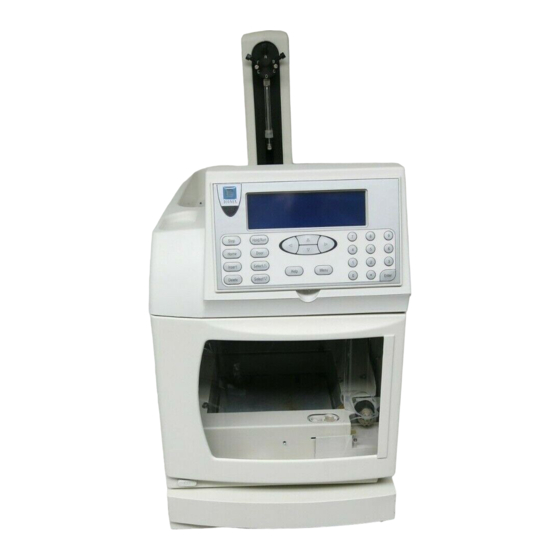
2 • Description Overview of Features Figure 2-1 illustrates the main features of the AS Autosampler. Sample and Prep Syringes Flush Reservoir Front Panel Autosampler Compartment Power Switch Figure 2-1. AS Operating Features Doc. 065051-03 1/08... - Page 20 Section 2.2). The front panel permits manual control of AS functions. Power Switch The power switch is in the lower left corner of the AS. The switch functions only when the door is fully closed. Autosampler Compartment The autosampler compartment contains a stationary sample tray and an XYZ...
-
Page 21: Front Panel Features
Valve Options One or two injection valves can be installed in the AS autosampler compartment. Or, the AS can be configured without an injection valve and instead be connected to one or two valves installed in other chromatography system modules. Two injection valves are required for simultaneous injections. -
Page 22: Keypad Button Functions
Sends the needle arm to its home position. This button functions only Home when the AS is in Local mode. If a schedule is in progress, it must be on hold. If you press Home when a schedule is on hold, and then resume the schedule, the needle arm returns to the location it was in when you pressed Home. - Page 23 2 • Description Button Function If you press the Door button when a sequence (or front panel Door schedule) is running, a message screen indicates whether it is currently safe to open the door. If it is, the screen displays for how much longer it is safe to open the door.
-
Page 24: Display Screens
AS Autosampler Operator’s Manual 2.2.2 Display Screens The LCD displays status information and allows access to all AS operations. When the power is turned on, the AS performs an initialization sequence (see Section 3.1.1) and then displays the screen. Figure 2-3... - Page 25 2 • Description To access other AS screens: Press the button. The appears (see Figure 2-4). Menu MENU of SCREENS MENU of SCREENS FLUSH/PRIME MAIN STATUS TIME FUNCTION IN DETAIL STATUS METHOD MENU DIAGNOSTIC MENU SCHEDULE TIME FUNCTION OUT MODULE SETUP MENU Help Prompt Figure 2-4.
-
Page 26: Autosampler Compartment
AS Autosampler Operator’s Manual Autosampler Compartment Prep Syringe (Optional) Sample Syringe Reagent Reservoir (Optional) Flush Reservoir XYZ Sampling Needle Arm Flush, Waste, and Inject Ports Injection and/or Diverter Valves (Optional) Sample Tray (for Vials or Well Plates) Figure 2-5. Autosampler Compartment Features... -
Page 27: Syringe And Reservoir Organizer
2 • Description 2.3.1 Syringe and Reservoir Organizer The organizer on top of the autosampler holds the sample syringe, 1 L flush reservoir, and the optional prep syringe and reagent reservoirs (see Figure 2-5). Sample Syringe Functions The sample syringe performs these operations: •... - Page 28 The reagent reservoir connects to port A on the sample prep valve. Additional reservoirs can be connected to ports B, C, and D. Commands from the AS front panel screens or from Chromeleon or Chromeleon Xpress let you select the reservoirs.
-
Page 29: Sampling Needle Arm
The needle height (the distance from the tip of the needle to the bottom of the vial or well) can be adjusted, allowing operations such as liquid-liquid extraction.You can set the needle height in a Chromeleon or Chromeleon... -
Page 30: Sampling Needle Assembly
1 mL or less PEEK Needle with Sample syringe volumes 061267 8.5 mL line greater than 1 mL a. The 8.5 mL sampling needle assembly is standard when the AS is configured with the simultaneous injection option. Doc. 065051-03 1/08... -
Page 31: Flush, Waste, And Inject Ports
2 • Description 2.3.4 Flush, Waste, and Inject Ports The flush port flushes the outside of the sampling needle with fluid from the flush reservoir. Excess fluid flows to the waste port. The waste port accepts waste fluid from the sampling needle and the flush port, and directs it out the drain line. - Page 32 ° temperatures above 40 Well Plates and Trays Dionex recommends using well plates in the AS if you have limited amounts of sample or if you require more than 100 sample positions. Follow these guidelines when using well plates: •...
-
Page 33: Injection Valve Options
• In the Load position, sample flows from the AS inject port line, through the valve, and into the sample loop, where it is held until injection. Eluent flows from the pump, through the valve, and to the column, bypassing the sample loop. -
Page 34: Sample Temperature Control Option
2-9). Sample Temperature Control Option Figure 2-9. AS with Sample Temperature Control Option NOTE The temperature inside the autosampler compartment may exceed ambient by up to 2 °C. The sample temperature control option is recommended for samples that are temperature sensitive. -
Page 35: Simultaneous Injection Option
In Chromeleon or Chromeleon Xpress, the two chromatography systems and the AS are configured into a single timebase and each system is assigned a unique device name and channel. This lets you monitor and control both systems from one Control panel and run all samples in one sequence. -
Page 36: Concentrator Injection Option
8.5 mL sampling needle assembly must also be installed (see Section 2.3.3). The AS is capable of delivering at a maximum pressure of 690 kPa (100 psi). When setting up concentrator injections, make sure to select syringe speeds that will keep the backpressure below 690 kPa (100 psi), taking into account the pressure from the installed tubing and the concentrator column. -
Page 37: Rear Panel Features
The USB receptacle provides a connection to the Chromeleon or Chromeleon Xpress computer. To enable computer control of the autosampler, connect a USB cable between the USB receptacle on the AS rear panel and a USB port on the computer or USB hub. See Section B.3.8... -
Page 38: Ttl/Relay Connectors
5.18. The power cord plugs into the IEC 320 three-prong receptacle. The power supply cord is used as the main disconnect device. Make sure the socket-outlet is located near the AS and is easily accessible. Le cordon d'alimentation principal est utilisé comme dispositif principal de débranchement. -
Page 39: Autosampler Control
2.5.1), or remotely, with a personal computer on which Chromeleon or Chromeleon Xpress software is installed (see Section 2.5.2). TTL input signals from an integrator or other remote controller can also be used to control the AS. Appendix E for details about TTL control. 2.5.1... - Page 40 You program, save, and edit schedules from the screen (see SCHEDULE Figure 2-12). The AS can store up to nine schedules in memory. The stored schedules are retained in memory when the AS is turned off. Section D.6 describes how to create schedules.
- Page 41 2 • Description Each injection in a schedule is assigned a method (a series of operating instructions that tells the AS how to perform a single injection). A method consists of the following three phases: Method Phase Used To Examples...
-
Page 42: Computer Control (Locked Remote Mode)
2-13) immediately selects the Locked Remote mode. In this mode, you cannot change any operating parameters from the front panel keyboard. To return the AS to Local mode, clear the Connect check box on the AS Control panel. Figure 2-13. Example AS Control Panel... -
Page 43: System Wellness And Predictive Performance
In Automatic mode, you create a list of samples (a sequence) to be processed automatically. The sequence defines a series of vials to be sampled and the AS operating parameters to run on each vial. The sequence is similar to a front panel schedule (see Section 2.5.1),... - Page 44 Chromeleon Commands dialog box (press the F8 key or select Command on the Control menu to open the Commands dialog box). You can view and reset the usage counters for the various replaceable parts on either the AS Wellness panel (see Figure 2-14) or the...
-
Page 45: Theory Of Operation
The wait operation is a step in the sample prep phase of a method. After performing all other sample prep steps, the AS waits for a continue command before performing the method’s timed events. The continue command can be sent via the front panel... -
Page 46: Overlapping Sample Preparation
When the wait operation is at the end of the sample prep phase (the default), the overlaps sample preparation. This means that while data collection is occurring for one injection, the AS performs the sample prep steps for the next injection (see Figure 2-15). -
Page 47: Running Samples Without Overlap
Hold/Run performs the schedule lines without requiring additional commands. This allows the to act as the system master (the AS controls the system by sending TTL signals to start the pump and detector methods). To disable the wait operation, press... -
Page 48: Understanding The Cycle Time
Understanding the Cycle Time Cycle time is an optional feature that can be used to control the time between injections. When a method is assigned a cycle time, the AS delays sample injection until the specified time has elapsed since the previous injection. -
Page 49: Operating Events During A Schedule
2 • Description 2.7.6 Operating Events During a Schedule • Figure 2-19 shows the order of events during a schedule when the wait operation is enabled. • Figure 2-20 shows the order of events during a schedule when the wait operation is disabled. Section 2.7.1 for details about the wait operation. - Page 50 AS Autosampler Operator’s Manual Schedule Started Preparing to Run: Flush Inject Port and Wash Needle Method Starts for Method Starts for Method Starts for Injection #1 Injection #2 Injection #3 Continue as Shown Flush Inject Port and Flush Inject Port and...
- Page 51 Wash Needle Method Starts for Method Starts for Method Starts for Injection #1 Injection #2 Injection #3 Continue as Shown Flush Inject Port and Flush Inject Port and for Method #2 Until Wash Needle Wash Needle Last Scheduled Injection Completed...
-
Page 52: Understanding The Status Display During A Run
SCH 1 LINE 10 Help Prompt Figure 2-21. Detail Status Screen Example Notes • field is updated when the AS loads the loop for the next INJ# injection. • field and the timed events clock are reset to zero at... -
Page 53: Operating Events During Flushing And Priming
• Before each injection, while the schedule or sequence is running Flushing can also be initiated manually when the AS is idle, or as a step in the sample prep phase of a Chromeleon or Chromeleon Xpress program or front panel method. -
Page 54: Sample And Prep Syringe Fluid Schematics
AS Autosampler Operator’s Manual Priming The AS performs the following operations during priming: • The sampling needle arm moves to the waste port and expels any fluid from the needle. • The sampling needle arm moves to the flush port and delivers a volume of flush fluid. - Page 55 2 • Description Figure 2-23 shows the flow paths through the sample syringe valve ports for the two valve positions: • In the needle position, flow is between ports A–B, C–D, and E–F. • In the flush position, flow is between ports A–F, B–C, and D–E. Needle Position Flush Position To Flush...
- Page 56 AS Autosampler Operator’s Manual Reagent Holding Loop (Front Fitting) (Back Fitting) (To/From Needle) Prep Sample Syringe Syringe Valve Valve (Front Fitting) Sampling Needle Line (Back Fitting) (Behind Port S*) Reagent B (Optional) Prep Sample Syringe Syringe Reagent C (Optional) Sampling...
-
Page 57: Getting Ready To Run
Turn On the Power Press the power switch in the lower left corner of the front door to turn on the AS power. When the power is turned on, a series of screens are displayed and the autosampler performs a power-up sequence. -
Page 58: Fill The Vials Or Wells And Load The Sample Tray
NOTE For 0.3 mL and 1.5 ml vials (any type), Dionex recommends using vial caps with slit septa only (see Section 2.3.5). - Page 59 3 • Operation and Maintenance Figure 3-2). This ensures temperature stability and minimizes condensation, especially at low temperature set points. Tray Covers (for empty positions) Sample Vials Figure 3-2. Installing Tray Covers (Sample Temperature Control Option Only) 5. Install the tray in the autosampler compartment. 6.
- Page 60 NOTE Changing the needle height is not recommended when sampling from a micro-well well plate, because the well depth is shallow. You can adjust the needle height in a deep-well well plate as required, provided the needle remains submerged in sample. This ensures accurate sample aspiration.
- Page 61 3 • Operation and Maintenance 6. Orient the well plate with well A1 at the front-left corner and set the well plate in the well plate tray (see Figure 3-3). 7. Fill another well plate and install it on the right side of the tray. The two plates must be of the same type.
- Page 62 AS Autosampler Operator’s Manual 11. Close the autosampler compartment door. Make sure the door remains closed during operation. If you open the door during operation, the sampling arm stops immediately. If a schedule is running, it is ended. To safely open the door during operation, press the Door button (see Section 3.9...
-
Page 63: Selecting Computer Or Front Panel (Local) Control
3 • Operation and Maintenance Selecting Computer or Front Panel (Local) Control When the AS is powered up, it is always in front panel (Local) control. The MAIN screens indicate this by displaying in the operating mode field. DETAIL LOCAL... -
Page 64: Connecting To Chromeleon Or Chromeleon Xpress
NOTE If Chromeleon Xpress is installed, starting the client automatically displays the panel tabset. c. To display the AS Control panel, select the Autosampler tab on the panel tabset (see Figure 3-6). Doc. 065051-03 1/08... - Page 65 3 • Operation and Maintenance d. Verify that the Connect check box is selected. If it is not, click the box to connect the AS to Chromeleon or Chromeleon Xpress. Figure 3-6. AS Control Panel Doc. 065051-03 1/08...
-
Page 66: Running A Sequence Of Injections In Chromeleon Or
(by editing an existing program). In addition to commands for loading and injecting the sample, a program for the AS can include commands for setting up the autosampler (syringe speed, sample needle height, etc.) and for preparing the sample before injection (pipetting, mixing, flushing, etc.). -
Page 67: Default Operating Parameters
3 • Operation and Maintenance Default Operating Parameters Table 3-1 lists the factory-set values for AS operating parameters: Operating Screen Parameter Default Value Method Sample Prep Step 1 wait step only Method Setup Cycle Time Sample Needle Height 2 mm 20 °C... -
Page 68: Specifying Sample Positions
AS Autosampler Operator’s Manual Specifying Sample Positions When creating a schedule or sequence of injections, use the following guidelines to specify sample positions in the vial or well plate sample tray. 3.4.1 Vial Tray Sample Positions For the 49-position vial tray, vial... -
Page 69: Well Plate Tray Sample Positions
For example, well plate position LA1 identifies the well located at position A1, in the well plate installed on the left side of the AS well plate tray. When the well plate is installed in the tray, position LA1 is in the... -
Page 70: Specifying Injection Volumes
AS Autosampler Operator’s Manual Specifying Injection Volumes The range of injection volumes the AS can deliver to the injection valve depends on the size of the sample syringe installed on the AS and on the sampling mode selected on the screen (see Section 3.6.2). - Page 71 3 • Operation and Maintenance μ μ increments. For volumes of 100 L or greater, specify the value in 1 increments. Figure 3-10. Sequence Wizard: Specifying the Injection Volume Figure 3-11. Sequence Control Panel: Specifying the Injection Volume Doc. 065051-03 1/08...
-
Page 72: Sample Injection Types
Sample Injection Types 3.6.1 Overview The type of injection the AS performs for a particular sample depends on several factors, including the number of systems the AS is connected to and whether a sample loop or concentrator column is installed on the injection valve. - Page 73 3 • Operation and Maintenance During an injection, the injection type is displayed on the Chromeleon or Chromeleon Xpress Control panel (see Figure 3-12) and on the DETAIL screen (see Figure 3-13). STATUS Figure 3-12. Injection Type Shown on Control Panel DETAIL INJECTING VIAL#:...
-
Page 74: Determining The Injection Type
AS Autosampler Operator’s Manual 3.6.2 Determining the Injection Type To determine the injection type performed by the AS, first select the sample mode on the screen (see Figure 3-14). SYSTEM PARAMETERS Press , and to go to the screen. Menu, 5... -
Page 75: Determining The Sample Loop Injection Type
However, better precision is achieved with a larger cut volume. If you enter a cut volume of 0, the AS draws only the injection volume from the vial or well. - Page 76 AS Autosampler Operator’s Manual 1. Enter the size of the installed loop on the PLUMBING CONFIGURATION screen (see Figure 3-15). Press , and to go to the Menu, 5 PLUMBING screen. CONFIGURATION PLUMBING CONFIGURATION LOOP SIZE V1: LOOP SIZE V2:...
- Page 77 3 • Operation and Maintenance • If you enter an injection volume equal to or larger than the installed loop size, the AS performs a full-loop (or large-loop) injection. • If you enter an injection volume smaller than the loop size, the AS performs a partial-loop or partial-loop, limited-sample injection.
-
Page 78: Guidelines For Sample Volumes Used, Loop Sizes, And Injection Volumes
Injection Volumes Sample Volumes Used for Each Type of Sample Loop Injection Table 3-5 shows the volume of sample the AS aspirates from the sample vial or well plate well and the volume of sample injected onto the column. Injection Type... - Page 79 3 • Operation and Maintenance Full-Loop Sample Volume Examples For full-loop injections, if the injection volume is more than 4 times the loop size, the full injection volume is aspirated. The excess aspirated sample is flushed through the loop, but the amount injected is equal to the loop size.
- Page 80 AS Autosampler Operator’s Manual Partial-Loop and Partial-Loop, Limited-Sample Volume Examples For partial-loop injections, the amount of sample aspirated is equal to the injection volume + 2 times the cut volume. The amount injected is equal to the injection volume. For partial-loop, limited-sample injections, the amount of sample aspirated and injected is equal to the injection volume.
- Page 81 3 • Operation and Maintenance Table 3-9 also lists the maximum injection volume that can be specified in the Chromeleon or Chromeleon Xpress sequence or in the front panel schedule. Sample Sampling Maximum Maximum Sample Syringe Needle Assembly Loop Size Injection Volume ≤1,000 μL 500 μL...
-
Page 82: Normal, Full-Loop Injections
3.6.5 Normal, Full-Loop Injections For a normal, full-loop injection, the AS draws a volume of sample from the sample vial or well plate well. The volume of sample drawn depends on the loop size and the specified injection volume (see Section 3.6.4... - Page 83 Full-Loop Injection Notes • Entering an injection volume equal to or greater than the sample loop size sets up the AS for a full-loop injection. The actual volume of sample injected equals the volume of the sample loop installed. •...
-
Page 84: Normal, Large-Loop Injections
The injection sequence for a normal, large-loop injection is the same as described for a normal, full-loop injection (see Section 3.6.5). However, when a large loop (200.0 to 7000.0 μL) is installed, the AS draws a set amount (500 μ L) of extra sample from the vial for flushing the loop, instead of drawing a factor of the loop volume (see Section 3.6.4... -
Page 85: Normal, Partial-Loop Injections
3.6.7 Normal, Partial-Loop Injections For a partial-loop injection, the AS draws the volume of sample to be injected from the sample vial plus two times the cut volume.The cut volume specifies a volume of sample to be “cut” (or omitted) from each side of the sample during the injection process. - Page 86 AS Autosampler Operator’s Manual Setting Up a Partial-Loop Injection 1. On the screen (see Section C.6.5), select SYSTEM PARAMETERS in the field. NORMAL SAMPLE MODE 2. In the Chromeleon or Chromeleon Xpress sequence (see Figure 3-19) or in the front panel schedule (see Section D.3), enter an injection...
- Page 87 Injection volume: 50 μ Cut volume: 20 μ To perform the injection, the AS aspirates 90 μ L from the sample vial (the inject volume plus double the cut volume) and delivers it to the injection valve. Then, enough flush fluid is drawn into the syringe to position the sample.
-
Page 88: Normal, Partial-Loop, Limited-Sample Injections
3.6.8 Normal, Partial-Loop, Limited-Sample Injections For a partial-loop, limited-sample injection, the AS draws only the volume to be injected from the sample vial. The AS positions the sample in the loop and injects it onto the column (see Figure 3-22). - Page 89 Injection volume: 50 μ μ Cut volume: 0 To perform the injection, the AS aspirates 50 μ L from the sample vial (the inject volume) and then enough flush fluid is drawn into the syringe to position the sample. The 50 μ...
-
Page 90: Simultaneous Injections
AS Autosampler Operator’s Manual 3.6.9 Simultaneous Injections The AS must be in simultaneous mode to perform a simultaneous injection (see Section 3.6.2). In simultaneous mode, the AS delivers equal volumes of sample to two injection valves (see Figure 3-23). Each injection is a full-loop size. - Page 91 3 • Operation and Maintenance Setting Up a Simultaneous Injection The AS must be equipped with the simultaneous injection option in order to perform simultaneous injections. The following setup steps are required: • Follow the instructions in Section B.3.5 to connect the AS to two injection valves (either in the autosampler compartment or two IC systems).
- Page 92 AS Autosampler Operator’s Manual Example Program for Simultaneous Mode The following example Chromeleon or Chromeleon Xpress programs show the AS commands for sample loading and injecting when the autosampler is in simultaneous mode. Commands differ slightly, depending on where the valves are installed.
- Page 93 3 • Operation and Maintenance ;Switch the first inject InjectValve_1.InjectPosition valve to Inject ;Switch the second InjectValve_2.InjectPosition inject valve to Inject ;Sweep the sample onto Inject the column ;Wait for the injection to Wait InjectState finish Example Simultaneous Injection Program: Two Valves Installed in an ICS-1000/1500/2000 ;Switch the first inject 0.000...
-
Page 94: Concentrate Injections
AS Autosampler Operator’s Manual 3.6.10 Concentrate Injections The AS must be in concentrate mode to perform a concentrate injection (see Section 3.6.2). In concentrate mode, the AS draws the volume to be injected from the sample vial and delivers it to a concentrator column (see Figure 3-24). - Page 95 3 • Operation and Maintenance Setting Up a Concentrate Mode Injection 1. Install a concentrator column on the injection valve. 2. If the sample syringe volume is greater than 1 mL, install an 8.5 mL sampling needle assembly (P/N 061267). See Section 5.4 installation instructions.
- Page 96 AS Autosampler Operator’s Manual Figure 3-25 shows the Program Wizard Sampler Options tab page with the Concentrate function selected. Figure 3-25. Program Wizard Sampler Options for Concentrate NOTE Be sure to select syringe speeds that will keep the backpressure below 690 kPa (100 psi), taking into account the pressure from the tubing and the concentrator column.
- Page 97 3 • Operation and Maintenance Example Program for Concentrate Mode (Matrix Elimination) The following example Chromeleon or Chromeleon Xpress program shows the AS commands when the autosampler is in concentrate mode. Commands similar to these could be used for a matrix elimination application.
-
Page 98: Sequential Injections
3.6.11 Sequential Injections The AS must be in sequential mode to perform sequential injections (see Section 3.6.2). In sequential mode, the AS delivers sample to two separate chromatography systems. Each system is operated independently and can have a different sample and sample volume injected. - Page 99 Figure 3-26. Sequential, Full-Loop Injection Sequence NOTE Partial-loop and partial-loop, limited-sample injections can also be performed in sequential mode. The sequences of events for these injection types are the same as for normal mode, except for selection of the diverter valve position. Doc. 065051-03 1/08...
- Page 100 1. Follow the instructions in Section B.3.6 to install the sequential injection diverter valve, connect the AS inject port tubing to the diverter valve, and connect the diverter valve to the injection valves on two systems. 2. Calibrate the inject port volume of each system. This is the volume...
- Page 101 Section 3.6.8. Example Program for Sequential Mode The following example Chromeleon or Chromeleon Xpress program shows the AS commands for sample loading and injecting when the autosampler is in sequential mode. ;The timebase acquires Sampler.AcquireExclusiveAccess exclusive control of the AS, to...
-
Page 102: Sequential Concentrate Injections
AS Autosampler Operator’s Manual 3.6.12 Sequential Concentrate Injections In sequential concentrate mode, the AS delivers sample to two separate systems. A concentrator column replaces the sample loop on each injection valve. Each system is operated independently and can have a different sample and sample volume injected. - Page 103 1. Follow the instructions in Section B.3.6 to install the sequential injection diverter valve, connect the AS inject port tubing to the diverter valve, and connect the diverter valve to the injection valves on two systems. 2. Install a concentrator column on each injection valve.
-
Page 104: Selecting Syringe Speed Settings
3.7.2). Controlling the Backpressure The AS is capable of delivering at a maximum pressure of 690 kPa (100 psi). The syringe speed affects the backpressure produced at the inject port and needle seal; a faster syringe speed produces more backpressure than a slower speed. -
Page 105: Selecting Syringe Speeds On The Control Panel
3 • Operation and Maintenance 3.7.1 Selecting Syringe Speeds on the Control Panel 1. Go to the Autosampler Control panel (see Figure 3-31). Under Syringe, select the desired speeds for aspirating and dispensing liquids during priming and flushing. 1 is the slowest speed and 5 is the fastest. -
Page 106: Entering Syringe Speeds In The Program
The aspirate and dispense speeds selected for priming are also used for flushing, and vice versa. • If the AS is in concentrate mode, select a speed of 4 or less for dispensing during flushing and 2 or less for dispensing during loading. - Page 107 3 • Operation and Maintenance 2. Place the cursor in the list of autosampler setup commands (for example, after the Wait FlushState command) and press the Enter key twice to create two empty lines. 3. Press the F8 key to open the Commands dialog box. 4.
- Page 108 Two new commands are added to the program. Figure 3-34. Syringe Speed Commands in the Program NOTE If the AS is in concentrate mode, you can also enter separate aspirate and dispense syringe speeds for the Concentrate, Reagent Prime, and Reagent Flush functions.
-
Page 109: Syringe Speed And Tubing Size Guidelines
3 • Operation and Maintenance Syringe Speed and Tubing Size Guidelines The AS is capable of delivering at a maximum pressure of 690 kPa (100 psi). Several factors affect the system backpressure, including the syringe speed, syringe size, and the IDs and lengths of the sample loop and the tubing used to connect the inject port and the injection valve. - Page 110 AS Autosampler Operator’s Manual Prep Syringe Size Prep Syringe Speed Flow Rate (mL/min) 250, 500, and 1,000 μL 0.03 0.09 0.24 0.60 1.20 1.80 2.5, 5, and 10 mL 2.40 4.80 7.20 15.00 Table 3-12. Flow Rates Provided by the Prep Syringe a.
- Page 111 3 • Operation and Maintenance System #1 Backpressure Calculations: A 5 mL syringe and a syringe speed of 2 is assumed for this example. Tubing Tubing Backpressure Flow Rate Backpressure Length from tubing (mL/min) Produced (cm) (kPa/mL/min/cm) (kPa) Needle Seal Line 1.60 2.40 177 kPa...
-
Page 112: Opening The Autosampler Door During Operation
AS Autosampler Operator’s Manual Opening the Autosampler Door During Operation Normally, the autosampler door must remain closed while the AS is running either a sequence in Chromeleon or Chromeleon Xpress or a schedule from the front panel. If the door is opened inadvertently, the sampling arm stops immediately and the sequence or schedule is ended. - Page 113 • When the AS is operating under front panel control, the door can be opened safely only when the sampling arm is in the home position and the status displays .
-
Page 114: Routine Maintenance
AS Autosampler Operator’s Manual • If the AS never reaches a status that allows opening the door, check for one of the following: • If the AS is operating under Chromeleon or Chromeleon Xpress control, check the run length specified for the program. The run length may need to be increased to allow a longer wait period between injections. -
Page 115: Periodically
(see Section 5.2.1). 3.10.3 Annually Perform the AS preventive maintenance procedure. An AS Preventive Maintenance Kit (P/N 060581) is available for this purpose. The kit provides parts and instructions for performing the procedure. 3.10.4 Manually Flushing the Inject Port Flush the inject port after refilling the flush reservoir. -
Page 116: System Shutdown
Enter 3.11 System Shutdown No special system shutdown procedure is required. If the AS is under Chromeleon or Chromeleon Xpress control, you can load a shutdown program at the end of the schedule to automatically shut down the system. The shutdown program turns off the pump flow, the suppressor current, the sample temperature control option (if installed), and other system devices. -
Page 117: Troubleshooting
Error Messages When an error occurs, a beep sounds and a message appears. Each message is identified by a number in brackets in the lower-right corner of the AS screen. To clear the message, press any key. The Moduleware (the instrument control firmware installed in each AS) also reports errors to Chromeleon or Chromeleon Xpress, where they are logged in the Audit Trail. - Page 118 Actions: • Turn the power off and then back on. • If the error message appears again, contact Dionex. • [331] Method does not exist. The schedule contains a method that does not exist. Possible Causes: Incorrect method number entered into the schedule.
- Page 119 [348] A failure has occurred during power up! The status of all tests run during power up are indicated on the Diagnostic Tests screen which follows this error message. At power-up, the AS electronics are tested. If one or more tests fails, this message appears. On the screen, an “F”...
- Page 120 AS Autosampler Operator’s Manual • [367] The computed sample injection volume exceeded the vial volume. The sample injection volume has been automatically reduced. Please confirm injection volume parameter. Actions: See Section 3.6.4 for the guidelines for sample volumes used, loop sizes, and injection volumes. See Section 2.3.5...
- Page 121 If the message reappears, contact Dionex. • [379] Response from syringe contained data errors. Possible Causes: Communication problem. Actions: Turn off the AS power and then turn on the power again. If the message reappears, contact Dionex. Doc. 065051-03 1/08...
- Page 122 [380] Response from syringe was too long. Receive buffer overflowed. Possible Causes: Communication problem. Actions: Turn off the AS power and then turn on the power again. If the message reappears, contact Dionex. • [381] An attempt was made to move the syringe to an illegal position.
- Page 123 Sensors are not working. Actions: • Replace the tray. • Replace the tray sensor card. Contact Dionex. • [387] An illegal vial number was specified. The type of tray installed determines which vial numbers can be used in methods and schedules. See Section 3.4...
- Page 124 A check mark should appear beside each installed option. • If an installed option is not checked, turn off the AS power and then turn on the power again and recheck the INSTALLED screen.
- Page 125 Dead battery on CPU board • Malfunctioning power supply Actions: If a temporary short is suspected, the AS can still be operated. You will need to re-enter any method and schedule information and customized system setup parameters. If the problem persists, contact Dionex.
- Page 126 2. Check for an obstruction in the autosampler compartment. 3. Check for freedom of movement in all three axes of the sampling arm. 4. Turn on the power again. If the problem persists, contact Dionex. • [414] Specified volume is larger than size of sample syringe.
- Page 127 4 • Troubleshooting • [415] Cycle time expired before INIT step was completed. When the cycle time expires, the AS ignores the cycle time and delays injection until the step is complete. See Section 2.7.5 INIT for details. Possible Causes: The selected cycle time was too short.
- Page 128 AS Autosampler Operator’s Manual • [429] Format of global database has changed. Reinitializing to default values. Possible Causes: • Dead battery on CPU board • Malfunctioning power supply Actions: Contact Dionex. • [430] Format of method/schedule database has changed. Reinitializing to default values.
- Page 129 If closing the door does not eliminate the problem, try turning the power off and then on again. If the problem persists, contact Dionex. • [439] Method/Schedule database has been corrupted. Reinitializing database. Possible Causes: • Dead battery on CPU board • Malfunctioning power supply Actions: Contact Dionex. Doc. 065051-03 1/08...
- Page 130 • Door magnet missing Actions: • The autosampler door must be closed to operate the AS. Close the door and restart the schedule, if necessary. • If the door appears closed, but the message still occurs, check for an obstruction that is preventing the door from closing completely.
- Page 131 Possible Causes: An error occurred during Y-axis movement of the sampling arm. The DSP was able to recover from the error and continue the motion. Actions: Occasional occurrences of this error can be ignored. If the problem persists, contact Dionex. Doc. 065051-03 1/08...
- Page 132 AS Autosampler Operator’s Manual • [450] Non-recoverable motion error occurred in Y-axis. Clear any physical obstructions and then press any key to reset system. Possible Causes: • Vial obstructing motion • Misaligned sampling needle arm Actions: • Remove the vial obstruction.
- Page 133 [453] Recoverable motion error occurred in inject valve. Possible Causes: • Valve in wrong position Actions: Turn off the AS power and then turn on the power again. If the message reappears, contact Dionex. • [454] Non-recoverable motion error occurred in inject valve. Clear any physical obstructions and then press any key to reset system.
- Page 134 • [475] Cannot run schedule. No DSP detected. Possible Causes: Electronic malfunction Actions: Turn off the AS power and then turn on the power again. If the message reappears, contact Dionex. • [476] Cannot run schedule. No sample syringe detected.
- Page 135 AS. • Check the fan intake under the AS and the fan exhaust in the back for any obstructions restricting airflow. Make sure there is at least 6 cm (2.5 in) of free space behind the AS for ventilation.
-
Page 136: Liquid Leaks
• Make sure the syringe is tightened. To tighten, hold the syringe at the top and bottom fittings and turn it clockwise (as viewed from the top) (see Figure 4-1). Tighten fingertight only; do not overtighten. Figure 4-1. Tightening the Syringe... -
Page 137: Leaking Drain Line Connection
4 • Troubleshooting 4.2.2 Leaking Drain Line Connection • Make sure the drain line is not crimped or otherwise blocked. • Make sure the drain line is not submerged in liquid in the waste container. Empty the container, if needed. •... -
Page 138: Condensation On Well Plate Covers
AS Autosampler Operator’s Manual Condensation on Well Plate Covers Condensation can form on the well plate covers of the micro-well plates if the tray temperature set point is at 4 °C and the ambient temperature and relative humidity in the laboratory are above 25 °C and 60% humidity. -
Page 139: Service
5 • Service This chapter describes AS Autosampler service and repair procedures that the user can perform. All procedures not included here, including electronics-related repair procedures, must be performed by Dionex personnel. For assistance, contact Dionex Technical Support. In the U.S., call 1-800-346-6390. Outside the U.S., call the nearest Dionex office. -
Page 140: Assemblies, Tubing, And Fittings
1 mL 044777 PEEK tubing: Green 0.75-mm Connecting the injection valve (0.030-in) ID port 6 (waste) to the AS drip 043276 Double-cone ferrule fitting tray 043275 10-32 double-cone bolt Sample loop, 25 μL... -
Page 141: Resetting The Usage Counters
NOTE Reset the counter for the XYZ sampling needle arm after lubricating or replacing the arm. Reset other usage counters after replacing the part. You can reset usage counters from either the AS Wellness panel in Chromeleon or Chromeleon Xpress (see Section 5.2.1) or on the front panel... -
Page 142: Resetting A Usage Counter On The As Wellness Panel
Resetting a Usage Counter on the AS Wellness Panel 1. Open a panel tabset in Chromeleon or Chromeleon Xpress and select the Autosampler tab. 2. Click the Wellness panel button to open the AS Wellness Panel (see Figure 5-1). Figure 5-1. Example AS Wellness Panel (Default Warning Values for All Parameters Shown) 3. -
Page 143: Resetting A Usage Counter On The Usage Log Screen
5 • Service 5.2.2 Resetting a Usage Counter on the Usage Log Screen 1. On the , press , and to go to the MENU of SCREENS USAGE LOG screen (see Figure 5-2). USAGE LOG RESET MODULE ON: nnnnnn hours BACKLIGHT: nnnnnn hours INSERTS INJ PORT:... -
Page 144: Replacing The Sample Or Prep Syringe
AS Autosampler Operator’s Manual Replacing the Sample or Prep Syringe Replace a sample or prep syringe after about 6,200 cycles of use. When the AS is operating under Chromeleon or Chromeleon Xpress control, a message is displayed in the Audit Trail when a syringe reaches this usage limit. If you are... -
Page 145: Removing The Existing Syringe
5 • Service 5.3.1 Removing the Existing Syringe 1. Using a flathead screwdriver, unscrew and remove the syringe drive connecting screw (see Figure 5-4). 2. Hold the syringe at the top and bottom and unscrew it from the valve. 3. Remove the white Teflon washer from the syringe valve port. -
Page 146: Filling The New Syringe And Removing Bubbles
AS Autosampler Operator’s Manual 5.3.2 Filling the New Syringe and Removing Bubbles Method A 1. Fill a container with isopropyl alcohol. Place the threaded end of the syringe into the container and slowly pull liquid into the syringe. 2. Remove the syringe from the liquid and point the threaded end up into the air. -
Page 147: Initializing The Syringe
5 • Service 5. Insert the syringe drive connecting screw removed in Section 5.3.1 and tighten fingertight. 6. Perform a flush cycle: a. Press , and to go to the screen. Menu Menu FLUSH/PRIME FLUSH/PRIME FLUSH PRIME VOLUME: VOLUME: 2000 RESERVOIR: FLUSH RESERVOIR: RES A... -
Page 148: Resetting The Syringe Usage Counter
5-7). Figure 5-7. Initializing the Syringe 5.3.5 Resetting the Syringe Usage Counter After replacing the syringe, reset the syringe usage counter from either the AS Wellness panel in Chromeleon or Chromeleon Xpress or on the front panel (see Section 5.2). - Page 149 If the sample syringe is 5 or 10 mL, an 8.5 mL sampling needle assembly (P/N 061267) is installed. The 8.5 mL assembly includes the same parts as the 1.2 mL assembly, plus a coupler and an additional length of tubing to increase...
-
Page 150: Removing The Old Sampling Needle Assembly
AS Autosampler Operator’s Manual Tubing 1.5-mm (0.062-in) ID Coupler Tubing 0.8-mm (0.032-in) ID Yellow Sleeves Bolt (P/N 052230) Bolt (P/N 052267) Ferrule (P/N 052231) Ferrule (P/N 064553) (Shipped unattached. Connect to the sample syringe after installing the needle assembly.) PEEK Needle Figure 5-9. - Page 151 5 • Service 4. The line that connects the sampling needle to the sample syringe is clipped to the upper-right side of the needle arm (see Figure 5-10). Using a 2.5-mm Allen wrench, remove the M3 screw that attaches the clip to the sampling arm.
- Page 152 AS Autosampler Operator’s Manual 6. The sampling needle line is coiled and held by a bracket and clamp on the upper-right side of the autosampler compartment (see Figure 5-11). To remove the tubing, use a flathead screwdriver to gently pry the center bracket apart. Then, lift the tubing out of the bracket and clamp.
- Page 153 5 • Service c. Tape one end of a piece of string or tubing to the end of the sampling needle assembly line. This will help you thread the new line through the autosampler later in the procedure. d. From the inside of the autosampler, pull the tubing into the autosampler compartment, along with the end of the attached string or tubing.
-
Page 154: Installing The New Sampling Needle Assembly
AS Autosampler Operator’s Manual 5.4.2 Installing the New Sampling Needle Assembly 1. From the top, carefully insert the needle into the needle block (see Figure 5-13). Make sure the needle is vertical and centered over the opening inside the block. - Page 155 The tubing must curve away from the needle arm assembly when the arm is moved toward the left/front of the autosampler (as viewed from the front). Adjust the tubing length to the needle when the needle is in the left/front corner and all the way down.
- Page 156 AS Autosampler Operator’s Manual 10. If you are replacing a 1.2 mL sampling needle assembly (P/N 054271), follow the steps below: a. Tape the string or tubing that was pulled into the compartment in Section 5.4.1, Step 8d to the free end of the new tubing. Pull the string or tubing, along with the new tubing, out the back of the compartment.
-
Page 157: Resetting The Sampling Needle Assembly Usage Counter
5.4.3 Resetting the Sampling Needle Assembly Usage Counter After replacing the sampling needle assembly, reset the Needle Cycles usage counter from either the AS Wellness panel in Chromeleon or Chromeleon Xpress or on the front panel (see USAGE LOG SCREEN Section 5.2). -
Page 158: Installing The Drip Tray
1. Hook the leak sensor on the tray as shown in Figure 5-16; make sure the sensor is pushed all the way down onto the tray edge. Leak Sensor (P/N 053669) Figure 5-16. - Page 159 Figure 5-17. Routing the Injection Valve Waste Line to the Drip Tray: Valve Installed in Another Module To connect the waste line when the AS is connected to two injection valves: 1. Insert the waste line from the first injection valve into the small round opening at the right front corner of the drip tray.
-
Page 160: Replacing The Needle Seal Assembly
Replacing the Needle Seal Assembly Replace the needle seal assembly after about 4,200 cycles of use (the cycle count increments each time the needle is inserted into the inject port). When the AS is operating under Chromeleon or Chromeleon Xpress control, a reminder message is displayed in the Audit Trail when the number of cycles reaches this usage limit. - Page 161 5 • Service If the AS is equipped with the diverter valve for sequential injections, disconnect the needle seal line from port S on the Disconnect diverter valve (see this line Figure 5-20). Figure 5-20. Diverter Valve: Disconnecting the Needle Seal Line 3.
- Page 162 Slot Figure 5-23. Inject Port 9. Reinstall the drip tray (see Section 5.6). 10. Reset the Needle Cycles usage counter from either the AS Wellness panel in Chromeleon or Chromeleon Xpress or on the front panel USAGE LOG (see Section 5.2).
-
Page 163: Aligning The Sampling Needle In The Inject Port
Automatic alignment, using Chromeleon or Chromeleon Xpress (Release 6.8 SP2 or later) • Manual alignment, using the AS front panel screens This section describes the alignment procedure in Chromeleon or Chromeleon Xpress. If Chromeleon or Chromeleon Xpress (Release 6.8 SP2 or later) is unavailable, refer to Section D.8... - Page 164 AS Autosampler Operator’s Manual To align the sampling needle in Chromeleon: 1. Open the Chromeleon Browser and open a panel tabset. 2. Select the Autosampler tab to open the AS Control panel (see Figure 5-24). Figure 5-24. Example AS Control Panel...
- Page 165 5 • Service 3. Under Wellness, click the Needle align button. The Needle Alignment panel appears (see Figure 5-25). Figure 5-25. Chromeleon Needle Alignment Panel 4. To complete the alignment procedure, follow the instructions on the panel and refer to the following notes: Step 1: For a better view of the needle and inject port during the alignment procedure, you can open the autosampler door after clicking Inject port align.
- Page 166 • After clicking Finish, the new calibration values are displayed on the panel. Write these values on the label inside the AS front door. 5. If you are performing this procedure after replacing the needle seal assembly, go on to calibrate the inject port volume (see Section 5.9).
-
Page 167: Calibrating The Inject Port Volume
5 • Service Calibrating the Inject Port Volume Calibrate the inject port volume at the following times: • After replacing the needle seal assembly • If reproducibility between injections is poor Two methods are available for calibrating the inject port volume: •... - Page 168 Calibration panel appears. The panel and calibration procedure differs, depending on whether the AS is configured for normal or sequential mode. • If the AS is in normal mode, refer to the instructions on the panel (see Figure 5-27) and to the notes on...
- Page 169 Make sure the sample syringe is free of bubbles (see Section B.3.14). • Step 1: Clicking Setup first empties the needle seal line. The AS then dispenses 25 μ L into the inject port. This nearly fills the needle seal line (minus a few microliters).
- Page 170 Continue clicking +1 uL until a tiny drop of liquid appears at the end of the needle seal line. If you go too far and more than a single small drop of liquid appears, click -5 uL. The AS will empty the line and then fill the line with 5 μ...
- Page 171 5 • Service Figure 5-28. Chromeleon Inject Port Volume Calibration Panel: Sequential Mode Notes for calibrating the inject port volume when in sequential mode: • Preparing: After disconnecting the diverter valve lines from the injection valves, route the lines outside the autosampler or chromatography compartment.
- Page 172 μ L/in) for the diverter line plus the volume of the needle seal line (which is written on a label on the tubing and inside the AS front door). Then, click Estimate. The AS dispenses the volume entered, which nearly fills the diverter and needle seal lines (minus a few microliters).
-
Page 173: Replacing The Leak Sensor
5 • Service 5.10 Replacing the Leak Sensor 1. Remove the drip tray from the autosampler (see Section 5.5). 2. Unhook the leak sensor from the drip tray and pull out the leak sensor cable until the connector is visible. 3. -
Page 174: Calibrating The Leak Sensor
The current measured value becomes the new calibration value. To calibrate the leak sensor from the Chromeleon Wellness panel: 1. Open the Chromeleon Browser and expand the Dionex Templates folder. 2. Expand the Panels folder and the Wellness folder. 3. On the right pane of the Browser window, double-click Dionex_autosampler_wellness.pan. - Page 175 5. Under , click Calibration: leak detector tray The AS calibrates the sensor and then uploads the new value to Chromeleon. Chromeleon stores the new calibration value as the current value. 6. To test the leak sensor, click under tray Diagnostic Tests: leak detector Doc.
-
Page 176: Removing The Sample Or Prep Syringe Valve
AS Autosampler Operator’s Manual 5.12 Removing the Sample or Prep Syringe Valve 1. On the , press to go to the MENU of SCREENS PLUMBING screen. CONFIGURATION 2. Move the cursor to the field or the SAMPLE SYRINGE CONFIG PREP SYRINGE field (depending on which syringe requires initialization). -
Page 177: Replacing The Sample Syringe Valve
Figure 5-32. Sample Syringe Drive Shaft Initial Positions If the slot in the drive shaft is not in the correct position, the syringe drive may need replacing. Contact Dionex for assistance. Do not attempt to manually turn the drive shaft. - Page 178 AS Autosampler Operator’s Manual 5. To verify that the syringe drive shaft is in the correct position, fill a syringe with deionized water and insert it into port D on the valve. Push liquid through the port and verify that it exits through port C.
-
Page 179: Replacing The Prep Syringe Valve
Figure 5-34. Prep Syringe Drive Shaft Initial Position If the slot in the drive shaft is not in this position, the syringe drive may need replacing. Contact Dionex for assistance. Do not attempt to manually turn the drive shaft. 4. Check the back of... - Page 180 AS Autosampler Operator’s Manual about 1.5 cm into the port. If the drive shaft position is incorrect, you will not be able to insert the paper clip more than about 1 cm into the port. In this case, rotate the valve 180 degrees and recheck the position.
-
Page 181: Replacing A Sample Or Prep Syringe Pump Assembly
The following syringe pump assemblies are available: Sample syringe (P/N 062382), dual sample syringe (P/N 062379), and sample prep syringe (P/N 062365) 1. Turn off the AS power. 2. Disconnect the liquid lines from the existing syringe valve. 3. Unplug the syringe cable from the rear panel connector. -
Page 182: Rebuilding The Injection Or Diverter Valve
1,000 cycles of use. When the AS is operating under Chromeleon control, a reminder message is displayed in the Audit Trail when the number of cycles reaches this usage limit. If the AS is operating under front panel control, the... - Page 183 5 • Service 3. If you are rebuilding an injection valve installed inside the AS autosampler, follow the steps below to pull the valve away from the compartment slightly, for better viewing of the valve parts during the procedure. a. Remove the drip tray as described in Section 5.5.
-
Page 184: Replacing The Well Plate Tray Thermal Pads
AS Autosampler Operator’s Manual 5.17 Replacing the Well Plate Tray Thermal Pads Replace the two thermal pads (P/N 064999) on the well plate tray annually. 1. Remove the well plates from the tray. 2. Starting at a corner, peel off the existing thermal pad from the tray. The pad is made of a sticky material, but there is no adhesive attaching it to the tray. -
Page 185: Changing The Main Power Fuses
5 • Service 5.18 Changing the Main Power Fuses The fuse holder is part of the main power receptacle on the rear panel of the AS autosampler compartment. 1. Turn off the main power. HIGH VOLTAGE—Disconnect the main power cord from its source and also from the rear panel of the AS. - Page 186 AS Autosampler Operator’s Manual 4. Reinsert the fuse holder into its compartment. The fuse holder is keyed to fit only in its proper orientation. Apply sufficient pressure evenly against the holder to engage the two locks. The holder is flush against the panel when both locks are engaged.
-
Page 187: A • Specifications
A • Specifications A.1 Autosampler A.1.1 Electrical Main Power 100 to 240 Vac, 50/60 Hz; 6 amps. The AS power supply is main voltage auto-sensing and requires no adjustment. Fuses Two 3.15 amp fast-blow IEC 127 fuses (P/N 954745) A.1.2 Environmental/Physical 10 to 40 °C (50 to 104 °F) -
Page 188: Valves (Optional)
AS Autosampler Operator’s Manual A.1.3 Valves (Optional) Injection One or two, two-position, six-port, electrically-activated Rheodyne valves, PEEK Diverter One two-position, six-port, electrically-activated Rheodyne valve, PEEK A.1.4 Injection Injections per Vial 1 to 99 Vial Sizes Available 0.3 mL polymer vials 1.5 mL glass vials... -
Page 189: Sample Temperature Control (Optional)
A • Specifications 25 μL standard; other sizes are available Injection Loop Size Concentrator Dionex ultra-low pressure; maximum injection pressure is 690 kPa Column (100 psi) Maximum Pressure 690 kPa (100 psi) Delivery A.2 Sample Temperature Control (Optional) Temperature 4 to 60 °C in 1 °C increments at 24 °C (75 °F) ambient, stable to Control Range ±0.2 °C... - Page 190 AS Autosampler Operator’s Manual Doc. 065051-03 1/08...
-
Page 191: B • Installation
If two AS Autosamplers are to be used with an ICS-3000 Detector/Chromatography module (DC), place one AS on the left side of the DC and one on the right side. Use the Second AS Kit (P/N 062578) to set up the AS on the right side (see Section B.3.7). -
Page 192: Unpacking
B.2 Unpacking Two or more persons should lift the AS, which weighs more than 18 kg (40 lb). Lift the AS only from each side of the cabinet bottom. Lifting from the front door will damage the door hinges. Au moins deux personnes peuvent soulever l'AS, qui pèse plus de 18 kg (40 lb). - Page 193 2. Remove the foam top cap. Figure B-4. AS with sleeve assembled over cradle Note: The AS is inserted into the bottom foam of the main shipping container. The tubing is coiled in front of the AS. 3. Using the handholds in the cradle, place the AS on the bench.
- Page 194 B-7). Be careful not to damage the drain tube. Figure B-7. AS sitting on foam spacer Note: The rear of the AS is aligned with the rear edge of the foam. Figure B-8. 5-cm (2-in) wide masking tape securing tubing within the recess at the rear of the AS 6.
- Page 195 10. Remove the sturdy ties and the polyethylene bag. 11. Open the front of the sheath and use the handles to set the pack and syringes on top of the main AS. 12. Slide the syringes into positions (see Figure B-13).
- Page 196 AS Autosampler Operator’s Manual Figure B-13. Fully assembled dual syringes with bottle Figure B-14. Shipping bracket hooked into frame and attached to sample arm and chassis with screws 13. Remove the sturdy tie, the two cap screws, and the bracket Figure B-15.
- Page 197 Shaft with polyethylene sleeve removed Note: Remember to save the shipping container and all packing material. After unpacking, save the shipping restraints. To stabilize the sampling arm and prevent damage, always reattach these shipping restraints before moving or shipping the AS. Doc. 065051-03 1/08...
-
Page 198: Autosampler Installation
Verify that all shipping restraints are removed Connect the syringe(s) and drain line Connect the injection valve (Optional) Connect the AS to the Chromeleon PC or to the Chromeleon Xpress PC (Optional) Install a diverter valve for sequential injections (Optional) Install a second AS kit... -
Page 199: Connecting The Syringes And Drain Line
Connecting the Syringes and Drain Line 1. Remove the acorn nut from the fitting on the sampling needle assembly, which extends from the AS rear panel. Gently pull the line out the rear panel until there is enough free tubing (about 45 cm (18 in)) to route the line to the front of the sample syringe. - Page 200 AS Autosampler Operator’s Manual 6. If the sample temperature control option is installed, locate the drain line (P/N 055075) in the AS Ship Kit (P/N 062381) and push the line onto the fitting on the lower right front corner of the sampler temperature control unit.
- Page 201 B • Installation Neutralisez les déchets acides ou caustiques avant de les jeter. Jetez les déchets aux règlements locaux. Neutralisieren Sie säurehaltige und ätzende Abfälle vor ihrer Entsorgung. Entsorgen Sie alle Abfälle entsprechend den lokalen Bestimmungen. 8. Connect the cable from the sample syringe to the SAMPLE SYRINGE connector on the rear panel (see Figure...
- Page 202 3. If you are installing additional reagent reservoirs, connect the lines from ports B, C, and/or D to the additional reservoirs. NOTE Port letters A through D on the prep syringe valve correspond to reagent reservoirs A–D on the AS front panel screens and in software controls. Port A...
-
Page 203: Connecting A Single Injection Valve
1. Open the AS and chromatography system module doors. 2. The needle seal line that extends from the inject port in the autosampler is coiled inside the AS door, on the right side. Route this line through the side slot on the AS (see... - Page 204 DC and then through the side slot on the AS. 6. If you are connecting the AS to an ICS-1000/1500/2000, this green waste line (labeled ) is connected with a union to a Teflon...
-
Page 205: Connecting Two Injection Valves
8. To ensure the green waste line stays in place in the opening in the AS drip tray, sharply bend the line about 12 mm (1/2 in) from the end, being careful not to restrict the inner diameter. - Page 206 Valves Installed in Two Chromatography System Modules 4. Route the green waste lines connected to port W (6) on each injection valve through the side slots to the AS drip tray. Insert one line into the small round opening in the tray (see Figure B-23).
- Page 207 B • Installation Connecting to Two Valves Installed in the AS 1. Route the outlet lines from the pump and column in both chromatography systems through the slot on the right side of the AS (see Figure B-28). Valve #2...
- Page 208 Valves Installed in the AS 4. Route the green waste lines connected to port W (6) on each injection valve through the side slots to the AS drip tray. Insert one line into the small round opening in the tray (see Figure B-30).
-
Page 209: Connecting A Diverter Valve (For Sequential Injections)
AS. A Diverter Valve Kit (P/N 063294) with the parts needed to install the valve is available. In addition to the kit, you will need a 5.5 mm nut driver to complete the installation. - Page 210 AS Autosampler Operator’s Manual 2. Dress the cable toward the rear of the AS. 3. Align the keyhole openings on the valve assembly with the four studs mounted on the right side of the autosampler compartment (see Figure B-32) and push the assembly onto the studs (see Figure B-33).
- Page 211 B • Installation Connecting the Plumbing 1. Connect the pink needle seal tubing from the AS inject port to port S on the diverter valve (see Figure B-34). Sample Out Line to System #1 Sample Out Line to System #2...
-
Page 212: Connecting A Second As To A Dual Ics-3000 System
When an ICS-3000 Detector/Chromatography module (DC) is configured with two injection valves, two AS Autosamplers can be connected to the DC. The first AS is installed on the left side of the DC and the second AS is installed on the right side. - Page 213 Figure B-37. Second AS Installation: Needle Seal Line Routed Out the Left Side of the AS 6. Align the sampling needle in the inject port (see Section 5.8). 7. Calibrate the inject port volume (see Section 5.9).
- Page 214 DC and then through the side slot on the AS. 11. To ensure the green waste line stays in place in the opening in the AS drip tray, sharply bend the line about 12 mm (1/2 in) from the end, being careful not to restrict the inner diameter.
-
Page 215: Connecting The As To Chromeleon Or Chromeleon
AS to a USB port on the Chromeleon or Chromeleon Xpress PC or on a USB hub. Typically, the AS is connected to a USB port on a system module that has an internal hub (for example, an ICS-2000 or ICS-3000 module). The system module is then connected to the USB port on the PC. - Page 216 (Document No. 065032). The manual contains information about USB compatibility issues with ICS-3000 systems. 1. Locate the USB cable (P/N 960777) in the AS Ship Kit (P/N 062380 or P/N 062381). 2. Plug the “B” connector of the USB cable into the USB receptacle on the rear panel of the AS.
- Page 217 Plug the USB cable’s “B” connector into the USB Plug the USB cable’s “A” receptacle on the AS connector into rear panel. port on the PC. Figure B-40. Example USB Connections: Connecting the AS Directly to the PC Doc. 065051-03 1/08...
-
Page 218: Connecting The Power Cord
SHOCK HAZARD—To avoid electrical shock, use a grounded receptacle. Do not operate the AS or connect it to AC power mains without an earthed ground connection. The power supply cord is used as the main disconnect device. Make sure the socket-outlet is located near the AS and is easily accessible. -
Page 219: Turning On The Power
DIAGNOSTIC TEST displayed. See Section C.9.2 if this occurs. • When the initialization procedures are complete and the AS has passed the diagnostics, the screen appears. After INSTALLED OPTIONS a few seconds (or if you press a button), the screen is displayed. -
Page 220: Selecting Module Setup Options
AS Autosampler Operator’s Manual B.3.11 Selecting Module Setup Options Press to go to the (see Figure B-41). Menu MODULE SETUP MENU MODULE SETUP MENU INSTALLED OPTIONS INJECT PORT ALIGN FRONT PANEL INTERLOCK BYPASS PLUMBING CONFIG TIME/DATE SYSTEM PARAMETERS Help Prompt Figure B-41. - Page 221 Figure B-43. System Parameters Screen Example: Normal Mode Selected 2. Move the cursor to the field and select the mode (see SAMPLE MODE Table B-1). Refer to Section 3-16 for details about the AS sample modes. SAMPLE MODE DESCRIPTION NORMAL (default) Injections to a single system CONCENTRATE...
- Page 222 Control panel or in a program. See Section 3.7 for details. • If the AS is always under front panel control (it is never connected to Chromeleon or Chromeleon Xpress), set the syringe speeds on the screen. See Section D.7 for details.
- Page 223 LOOP SIZE V2 the second injection valve. Select the Wait Operation (for Front Panel Operation Only) NOTE Do not complete this section if the AS will be controlled by Chromeleon or Chromeleon Xpress. The software enables the wait function automatically and ignores the setting on the screen.
-
Page 224: Configuring The As In Chromeleon Or Chromeleon Xpress
Install the software, enter the license, and connect the USB cable before turning on the AS power. • When you start the AS after connecting to the PC, the PC detects the new USB device. • You are given an option to either create a new timebase or to add the AS to an existing timebase. - Page 225 B • Installation Chromeleon or Chromeleon Xpress setup instructions. • After configuring the AS in one or two timebases, you can start Chromeleon or Chromeleon Xpress and connect to a Control panel (see Figure B-46). For Chromeleon Xpress, connection to a panel is automatic.
-
Page 226: Priming The Liquid Lines
AS Autosampler Operator’s Manual B.3.13 Priming the Liquid Lines This procedure explains how to prime the liquid lines from the Chromeleon or Chromeleon Xpress Control panel. If you prefer, you can use the screen on the front panel to prime the lines (see page 217). - Page 227 B • Installation 6. If the sample preparation option is installed, follow these steps to prime the lines from each installed reagent reservoir (see Figure B-49): a. Select the reagent reservoir, enter 2000 μ L in the Prime Volume field, and press Prime. b.
- Page 228 AS Autosampler Operator’s Manual Sample Syringe Valve Sampling Needle Assembly Sample Syringe Sampling Flush Reservoir Needle Figure B-48. Sample Syringe Fluid Schematic: System without the Sample Preparation Option Reagent Holding Loop (Front Fitting) (Back Fitting) (To/From Needle) Prep Sample Syringe...
- Page 229 PRIME Help Prompt Figure B-50. Initiating a Priming Cycle 7. Repeat the procedure as required (see the previous priming guidelines). 8. When priming is complete, there are often small air bubbles in the top area of the syringe. Remove the bubbles before proceeding. See Section B.3.14...
-
Page 230: Removing Bubbles From The Syringe
AS Autosampler Operator’s Manual B.3.14 Removing Bubbles from the Syringe 1. Fill a container with isopropyl alcohol. 2. Using a flathead screwdriver, unscrew and remove the syringe drive connecting screw (see Figure B-51). 3. Hold the syringe at the top and bottom and unscrew it from the valve. -
Page 231: Injection Valve Plumbing
μ A 25 L PEEK sample loop (P/N 042857) is installed between ports 1 and 4. Other sample loop sizes are available. Contact Dionex for information. Figure B-52 shows the valve connections. This information is for reference, should you need to replace any tubing or fittings. -
Page 232: Setting Up Chromeleon Or Chromeleon Xpress For Simultaneous Injections
Simultaneous Injections B.5.1 Assigning Unique Names to Devices NOTE If the AS will be connected to a dual ICS-3000 system, you may skip this section. The Chromeleon Server Configuration program automatically assigns unique names to each device in a dual ICS-3000. - Page 233 B • Installation In the example below, the device name for the second ICS-2000 in a timebase is renamed Pump_ECD_2. This device will be identified as System #2 on the Control panel. Doc. 065051-03 1/08...
- Page 234 In addition to renaming the device name on the General tab page, you also need to rename signals and other devices associated with System #2. For example, if System #2 is an ICS-2000 (as in the previous example), select the Signals tab, click Change, and add _2 to the signal name.
- Page 235 B • Installation Also, select the State Devices tab and add _2 to the name of each enabled device. Press F2 to edit a device name. See the following example: Doc. 065051-03 1/08...
-
Page 236: Creating Sequences, Programs, And Quantification Methods
Create a single QNT file that includes the components from both systems. Creating a Method File for Systems Sharing an AS For simultaneous injection analyses, create a single method file with all components for each detector channel included in one component list. - Page 237 If two anion (or two cation) detector channels were being used, the measured retention time for each anion (or cation) would appear in both Ret. Time columns, as in the following example: Doc. 065051-03 1/08...
- Page 238 AS Autosampler Operator’s Manual Doc. 065051-03 1/08...
-
Page 239: C • Display Screens
CONFIGURATION *Available only TEMP TIME/DATE with the sample STATISTICS* temperature option. SYSTEM LIQUID PARAMETERS CONTROL LOGS INJECT PORT MENU ALIGNMENT USAGE INTERLOCK BYPASS LEAK CAL & STATUS MESSAGE KEYBOARD TEST CODE VERSIONS Figure C-1. AS Menu Structure Doc. 065051-03 1/08... -
Page 240: Menu Of Screens
AS Autosampler Operator’s Manual C.1 Menu of Screens Pressing displays the , which provides top-level access Menu MENU of SCREENS to the menu structure. MENU of SCREENS FLUSH/PRIME MAIN STATUS TIME FUNCTION IN DETAIL STATUS DIAGNOSTIC MENU METHOD MENU SCHEDULE... -
Page 241: Main Status Screen
Screen Field Description Status Line The top line on the screen displays the instrument's current operating (top of status. The following status values are displayed as they occur: screen) IDLE No method is currently running. PREPARING TO The AS is performing pre-schedule operations, RUN SCHEDULE such as flushing. - Page 242 AS Autosampler Operator’s Manual Screen Field Description DILUTE... The AS is performing a dilution as part of the sample prep phase of the method. REAGENT The AS is priming the lines with reagent. PRIME... REAGENT The AS is flushing the inject port with reagent.
- Page 243 The AS is performing a calibration command CALIBRATION IN while under Chromeleon or Chromeleon Xpress PROGRESS control. VIAL# The number of the vial the injection volume is taken from. The AS updates the vial number after executing the step of the method’s INIT timed events. INJ#...
-
Page 244: Detail Status Screen
AS Autosampler Operator’s Manual Screen Field Description Control Mode Press Select Δ or Select ∇ to select (schedule) or DIRECT mode. When the AS is in mode, Direct CONTROL LOCKED RMT (schedule) or Control is always selected. DIRECT In Schedule mode, the screen displays the number of the currently CONTROL running schedule, the schedule line, and the method. - Page 245 C • Display Screens DETAIL INJECTING TIME: TTL1 VIAL#: INJ#: VOL: TTL2 METHOD: TRAY: RLY1 P10 mL 20 °C LOOP: TRAY: 100 / 25 RLY2 SIMULTANEOUS INJ VLV 1 LOCAL SCH 1 LINE 1 INJ VLV 2 Help prompt Figure C-5. Detail Status Screen: Simultaneous Injection Mode DETAIL INJECTING VIAL#:...
- Page 246 WP 2mL or 2 mL well plate) LOOP The size of the loop in microliters. Note: If the AS is equipped with two injection valves, two loop sizes are shown. If the AS is in concentrate mode, is displayed. CONCENTRATOR (Injection The type of injection performed.
- Page 247 C • Display Screens Injection Type Description NORMAL FULL Full-loop injection to one system NORMAL PARTIAL Partial-loop injection to one system NORMAL LS Limited-sample injection to one system NORMAL LARGE Large-loop injection to one system CONCENTRATE Concentrate injection to one system SIMULTANEOUS Full-loop injections to two systems simultaneously...
-
Page 248: Method Menu
NOTE A method can have a maximum of 100 steps. The total includes the sample prep steps, the method setup (which counts as one step), and the timed events steps. For example, a default method would have a total of four... -
Page 249: Sample Prep Screen
C • Display Screens C.4.1 Sample Prep Screen Use the screen to specify a sequence of operations to be SAMPLE PREP performed before the method’s timed events. NOTE See Section D.5.3 for details about how to define sample prep steps. SAMPLE PREP METHOD: PIPET... - Page 250 AS Autosampler Operator’s Manual Prep Operation Description DELAY Specifies for how long the AS waits (0.0 to 999.9 minutes) before proceeding to the next step in the sample prep phase (default=0.0). NEEDLE The height of the needle above the bottom of the vial, from 0 to 46 mm (default=2 mm).
- Page 251 C • Display Screens Prep Operation Description Flushes the needle with a specified volume, from 1 to 999 μL FLUSH (default=250 μL). The sample syringe and flush reservoir are always used for flushing. If the volume specified is greater than the syringe volume, the syringe takes multiple strokes to achieve the volume.
- Page 252 Prep Operation Description WAIT The AS waits for a continue command before proceeding with the method. The command can be from the front panel (pressing Hold/Run) or a TTL input. Each method must have one wait step and no more. Sample prep operations can be added before and after the wait step.
- Page 253 C • Display Screens Notes on Reagent Volume Ranges • μ If the source is a reservoir, the allowed range is 100 to 50,000 L. The default is 2,000 μ L if the syringe volume is less than 5,000 μ L, and 10,000 μ...
-
Page 254: Method Setup Screen
AS Autosampler Operator’s Manual C.4.2 Method Setup Screen Use the screen to set the initial conditions and default METHOD SETUP parameters for a method. METHOD SETUP METHOD: CYCLE TIME: SAMPLE NEEDLE HEIGHT: SAMPLE TRAY TEMPERATURE: °C WAIT FOR TEMP STABLE: Help Prompt Figure C-9. -
Page 255: Timed Events Screen
Available only when the (default set sample temperature control option is installed. point=20) WAIT FOR Specifies whether the AS should wait until the YES/NO TEMP STABLE temperature of the sample tray has stabilized before continuing. C.4.3... - Page 256 TIME = 0.00 NOTE If the schedule specifies an injection per vial of 0, then only the method’s sample prep steps occurs. VALVE1 If the AS is equipped with, or connected to, two LOAD/ VALVE2 INJECT injection valves (for simultaneous injections), these (simultaneous fields are used to select the position of each valve.
-
Page 257: Schedule Screen
1 to 9 will not start until you press Hold/Run or send a TTL/RLY run command. MISSING VIAL The action the AS takes if a vial is missing from SKIP/STOP ACTION the tray. Select to ignore the missing vial and... - Page 258 Section 3.5 for details. μ 1,000 to 4,700 μL If the AS is equipped with the simultaneous INJ VOL ( (simultaneous injection option, the injection volume is loaded (with 5 mL injection into the sample syringe and then delivered equally syringe) 1,000 to 8,000 μL...
-
Page 259: Module Setup Menu
C • Display Screens C.6 Module Setup Menu MODULE SETUP MENU INSTALLED OPTIONS INJECT PORT ALIGN FRONT PANEL INTERLOCK BYPASS PLUMBING CONFIG TIME/DATE SYSTEM PARAMETERS Help Prompt Figure C-13. Module Setup Menu Screen C.6.1 Installed Options Screen screen lists the optional features installed in the INSTALLED OPTIONS . -
Page 260: Front Panel Screen
AS Autosampler Operator’s Manual • If the AS is in a sequential injection mode and a diverter valve is installed, the diverter valve is listed on the screen (see Figure C-15). INSTALLED OPTIONS SAMPLE TRAY TEMPERATURE CONTROL SAMPLE PREPARATION INJECTION VALVE... -
Page 261: Plumbing Configuration Screen
C • Display Screens C.6.3 Plumbing Configuration Screen Use the screen to specify the plumbing PLUMBING CONFIGURATION options installed in the PLUMBING CONFIGURATION LOOP SIZE V1: LOOP SIZE V2: SAMPLE SYRINGE VOLUME: SAMPLE SYRINGE CONFIG: READY PREP SYRINGE VOLUME: READY PREP SYRINGE CONFIG: Help Prompt Figure C-17. - Page 262 Press Select Δ or Select ∇ to SYRINGE 500, 1,000, 5,000, VOLUME 10,000 μL scroll through the choices. If the AS is equipped with the (default=250) simultaneous injection option (see For simultaneous Section 3.6.9), select either the 5,000 or injection mode: 5,000 10,000 μL size.
-
Page 263: Time/Date Screen
C • Display Screens C.6.4 Time/Date Screen Use the screen to set the time and date on the real-time clock. TIME/DATE TIME/DATE ACTUAL TIME: 12:35:00 SET TIME: 12:34:56 DATE: JUNE 06 Help Prompt Figure C-18. Time/Date Screen Screen Field Description ACTUAL TIME Displays the time on the real-time clock. -
Page 264: System Parameters Screen
Use the screen to set default system operating SYSTEM PARAMETERS parameters. The parameters vary, depending on whether the AS is controlled exclusively from the front panel or if it is sometimes or always under Chromeleon or Chromeleon Xpress control. SYSTEM PARAMETERS... - Page 265 Thereafter, the AS performs the schedule lines without requiring additional run commands. Disabling wait allows the AS to act as a system master. The AS can send TTL signals to other modules in the system, thereby controlling system functions (starting the pump, starting the detector method, etc.).
- Page 266 1 in the field and the volume for system 2 in the field. FLUSH SYRINGE (This parameter is displayed only when the AS is 1 (slowest) to SPEED controlled exclusively from the front panel.) 5 (fastest)
-
Page 267: Inject Port Alignment Screen
C • Display Screens C.6.6 Inject Port Alignment Screen Use the screen to align the sampling needle in INJECT PORT ALIGNMENT the inject port. See Section D.8 for detailed instructions. NOTE You can also align the inject port from the Chromeleon or Chromeleon Xpress Control panel. -
Page 268: Door Interlock Bypass Screen
AS Autosampler Operator’s Manual C.6.7 Door Interlock Bypass Screen Use the screen to temporarily disable the DOOR INTERLOCK BYPASS autosampler compartment door lock. NOTE The door interlock bypass can be used only for Direct control, Local mode operation. It cannot be used for Schedule control or computer control (Locked Remote). -
Page 269: Flush/Prime Screen
If the AS is controlled by Chromeleon or Chromeleon Xpress, set the syringe speed on the Chromeleon or Chromeleon Xpress Control panel (see Section 3.7). If the AS is always controlled from the front panel, select the syringe speed on the screen SYSTEM PARAMETERS (see Section C.6.5). - Page 270 The sample syringe is always used for flushing. FLUSH SAMPLE SYRINGE FLUSH To start a flush cycle, first make sure the AS is in READY, FLUSH Direct Control mode; then press Select Δ or ACTION Select ∇ to select and press Enter.
-
Page 271: Time Function In Screen
CONTINUE: starts the schedule (if it is not currently TTL2 running), or continues the current schedule (if the AS is at the wait step of a method). A signal to TTL3 from the controlling device TRAY TEMP ON/OFF: turns the sample temperature control option on TTL3 and off. -
Page 272: Diagnostic Menu
POWER-UP Moduleware and USB BIOS code, the module’s ID number (if connected), and the serial number of the AS. This is the same power-up screen that displays when you turn on the AS AUTOSAMPLER MODULEWARE REV n.nn... -
Page 273: Diagnostic Tests Screen
C • Display Screens C.9.2 Diagnostic Tests Screen This screen lets you test the AS electronics components. DIAGNOSTIC TESTS DSP COMM SYRINGE COMM LEAKS XYZ HOME INTERLOCK INJECT VALVE Help Prompt Figure C-27. Diagnostic Tests Screen These tests are run automatically at power-up. If any test fails, this screen is displayed and indicates the status of each test: “--”... -
Page 274: Xyz Test Screen
AS Autosampler Operator’s Manual Test Description INJECT VALVE 1 If the AS is equipped with two injection valves (for INJECT VALVE 2 simultaneous injections), these tests check that each valve (simultaneous operates correctly. injection mode) C.9.3 XYZ Test Screen Use the screen to test operation of the sampling needle arm. -
Page 275: Temperature Statistics Screen
C • Display Screens Screen Field Description XYZ 1, 2, 3, 4 Allows entry of XYZ values for four needle arm positions. The numbers indicate the number of motor steps away from the home position. X SENSOR Indicates the current state of the X and Y sensors. The X and Y Y SENSOR sensors detect evenly spaced slots that indicate the home position and mark distance intervals. -
Page 276: Liquid Control Screen
AS Autosampler Operator’s Manual Screen Field Description MIN, MAX, TIME Displays the minimum and maximum values measured for the selected value, and the length of time the value has been monitored. An asterisk indicates the value being monitored. To select a value to monitor, move the cursor to the desired field and press Enter. - Page 277 C • Display Screens The AS must be in Local mode, Direct Control to manually control these functions. LIQUID CONTROL VIAL#: NEEDLE HEIGHT: ASPIRATE: from NEEDLE DISPENSE: SYRINGE SPEED: SYRINGE: SAMPLE INJ VALVE: LOAD ACTION: ASPIRATE Help Prompt Figure C-30. Liquid Control Screen...
- Page 278 Injection valve #1 is injection the bottom valve and injection valve #2 is the top mode) valve. DIVERTER If the AS is equipped with a diverter valve for (system 1) sequential injections, this field selects the valve (system 2) position. Doc. 065051-03 1/08...
-
Page 279: Logs Menu
C • Display Screens C.9.6 Logs Menu LOGS MENU USAGE LOG MESSAGE LOG Help Prompt Figure C-32. Logs Menu Screen Usage Log Screen Use the screen to: USAGE LOG • Monitor for how long various components have been in use •... - Page 280 Help Prompt Figure C-34. Usage Log Screen (Additional Parameters) Screen Field Description The number of hours the AS has been powered-up. MODULE ON BACKLIGHT The number of hours the backlight has been on. INSERTS INJ The number of needle insertions into the inject port since the PORT counter was last reset to 0.
- Page 281 Method does not exist Help Prompt Figure C-35. Message Log Screen NOTE All messages are cleared from the log when the AS power is turned off. Each message includes the time and date the message was recorded, the error code, and a brief description of the error.
-
Page 282: Leak Sensor Calibration And Status Screen
CALIBRATION Reports the voltage values set for the calibration. VALUE LOW LEAK Reports the minimum voltage reading that is interpreted as a dry THRESHOLD sensor. A reading below this voltage indicates a wet sensor. Doc. 065051-03 1/08... -
Page 283: Keyboard Test Screen
2. Continue pressing all buttons in turn. Only the most recently pressed button shows in reverse video. 3. To end the test and return to the , press Menu DIAGNOSTIC MENU twice. 4. If any buttons do not work, contact Dionex. Doc. 065051-03 1/08... -
Page 284: Code Versions Screen
VALVE: TTL1, DISABLED Chromeleon Xpress, a TTL connection is required TTL2 between the AS TTL output and a TTL input on the (default= IC system. This will allow you to control the TTL1 injection valve in the IC system from the AS front ENABLED panel. -
Page 285: D • Front Panel Control
AS is in Local mode (see Section 3.2). To change most fields, the AS must also be in Direct control. 1. Press a cursor arrow button to position the cursor in the field. 2. Enter the desired value, using the following buttons. -
Page 286: Running A Schedule Of Injections From The Front Panel
D.3 Running a Schedule of Injections from the Front Panel This section describes how to run a schedule of injections from the AS front panel. To run a schedule (sequence) of injections from the computer, refer to the Chromeleon or Chromeleon Xpress Help or user’s guide. -
Page 287: Selecting And Starting The Schedule
D • Front Panel Control D.3.1 Selecting and Starting the Schedule 1. Go to the screen. MAIN STATUS DETAIL STATUS 2. Position the cursor in the control mode field and press Select Δ or Select ∇ to select (schedule) control (see Figure D-1). -
Page 288: Placing A Running Schedule On Hold
Press STOP again to abort. Press HOLD/RUN to resume. Help Prompt Figure D-3. Stop Message Screen When a schedule is aborted, the AS performs the following sequence of operations: • The sampling needle arm moves to the waste port and empties any fluid from the needle. -
Page 289: Running Under Direct Control From The Front Panel
(Locked Remote mode), refer to the Chromeleon or Chromeleon Xpress Help. The AS must be in Direct Control to initiate a manual flush or priming cycle, or to perform certain maintenance or diagnostic procedures. The following AS functions can also be controlled directly (not as part of a schedule): •... - Page 290 Selecting Direct Control Parameters 1. Go to the screen (press Menu DETAIL STATUS 2. If the AS is not in Direct Control mode, position the cursor in the control mode field and press Select Δ or Select ∇ to select . Press...
-
Page 291: Creating Methods From The As Front Panel
(Local mode). To create methods (programs) from the computer, refer to the Chromeleon or Chromeleon Xpress user’s guide or Help. A method defines a series of operating instructions that tells the AS how to perform a single injection. A method consists of three phases: •... -
Page 292: Saving A Method
AS Autosampler Operator’s Manual 2. In the field, enter the number of an unused method. EDIT 3. Press Enter 4. Go to each method screen and enter the method parameters. • For details about defining sample prep steps, see Section D.5.3. -
Page 293: Defining Sample Prep Steps
Sample Prep Description Operation DELAY Specifies for how long the AS waits before proceeding to the next step in the sample prep phase. NEEDLE The height of the needle above the bottom of the vial. Moves a specified volume of sample from one vial to another. - Page 294 1.5 mL, aluminum 1 to 100 10 mL, plastic 1 to 49 NOTE To sample from a well plate, the AS must be under Chromeleon or Chromeleon Xpress control. • To enter a relative position, press Select Δ or Select ∇...
- Page 295 3. To select a prep operation, move the cursor one field to the right and press Select Δ or Select ∇ to scroll through the list of operations. As you select each type of operation, the parameters for that operation are displayed to the right.
- Page 296 DISABLED 4. Press Enter Specifying a Delay Between Prep Steps operation specifies the number of minutes the AS waits before DELAY proceeding to the next step in the sample prep phase. Number of Minutes to Delay Before Performing Next Step...
- Page 297 D • Front Panel Control Specifying a Needle Height operation specifies the height of the needle above the bottom NEEDLE of the vial. This height is used for , and operations. PIPET DISPENSE When pipetting, the height applies only to the source vial. The height is measured from the tip of the needle to the bottom of the vial.
- Page 298 AS Autosampler Operator’s Manual Pipetting Liquid from One Vial to Another operation uses the sample syringe to transfer liquid from a PIPET source vial to a destination vial. After pipetting, mix the destination vial before sampling from it. Be sure to specify enough mix cycles to completely mix the vial contents (see “Mixing a Vial”...
- Page 299 D • Front Panel Control Flushing the Needle The sample syringe is used to flush the needle with the specified volume of liquid. If you specify a volume greater than the syringe volume, multiple flushes are done. Volume to Flush Through Needle FLUSH Flush Volume...
- Page 300 AS Autosampler Operator’s Manual Diluting is available only if the sample preparation option is installed. The DILUTE following steps occur during a dilution: • The sample syringe picks up a volume of concentrate from the concentrate vial and dispenses it to the destination vial.
- Page 301 N (no change) (see notes) NOTE Although it is possible to select a vial or the flush reservoir as the reagent source, REAGENT PRIME designed to be used only when a reagent reservoir is the selected reagent source and the prep syringe is installed.
- Page 302 AS Autosampler Operator’s Manual Reagent Flush after Concentrator Loading or Reagent Priming is used to flush reagent onto the concentrator column REAGENT FLUSH after sample is loaded. See Section 3.6.10 for details about concentrator injections. The following steps occur during reagent flush: •...
-
Page 303: Selecting Method Setup Parameters
D • Front Panel Control • If the source is a vial, the range depends on the volume of the syringe: µL) Sample Syringe Reagent Prime/Flush Default ( µL) µL) Volume ( Range ( 100 to 1,000 100 to 1,000 1,000 (any size vial) 5,000 100 to 4,700... - Page 304 AS Autosampler Operator’s Manual The table below shows the value ranges for each parameter. See the following section for details about each parameter. Parameter Value Range Default Cycle Time 1 to 240 minutes Off (---) Sample Needle Height 0 to 46 mm 2 mm* 4 to 60 °C...
- Page 305 D • Front Panel Control Setting the Tray Temperature parameter is available only when the sample TRAY TEMPERATURE temperature control option is installed. Otherwise, this field displays “--” and is not illuminated. 1. On the screen, position the cursor in the METHOD SETUP TRAY field.
-
Page 306: Defining Timed Events Steps
AS Autosampler Operator’s Manual D.5.5 Defining Timed Events Steps To go to the screen: TIMED EVENTS 1. Go to the METHOD MENU. 2. Position the cursor in the field (TIMED EVENTS) 3. Press Enter Figure D-9 shows the default screen. - Page 307 NOTE When a cycle time is specified, the AS delays executing the time zero step until the specified time has elapsed since the previous injection (see Section 2.7.5...
- Page 308 AS Autosampler Operator’s Manual Controlling the Injection Valve parameter sets the position of the injection valve to either VALVE . A method's timed events can include only one Load and LOAD INJECT one Inject command. The Load command must precede the Inject.
-
Page 309: Editing A Method
METHOD MENU 2. In the field, enter the number of the method to be edited. EDIT 3. Go to the method screen to be changed and edit the parameters as required. 4. Save the method (see Section D.5.2). The changes can be saved to the same method number or to a new (unused) method number. -
Page 310: Example Method For Dilution
NOTE The sample preparation option is required for this method. This method uses the sample preparation option to dilute a sample before injection. In this method, the AS delivers 600 μ L of the concentrated sample from vial 6 and 5400 μ... -
Page 311: Creating A New Schedule
D • Front Panel Control D.6.1 Creating a New Schedule 1. Go to the screen. SCHEDULE If you are opening the screen for the first time after the power is turned on, the screen displays an empty (unused) schedule (see Figure D-12). -
Page 312: Saving A Schedule
Before beginning each injection, the AS checks that a vial is present in the scheduled position in the tray. If the vial is missing, the AS can either stop and wait, or skip the vial and continue. The action is specified in the schedule. -
Page 313: Defining Schedule Lines
D • Front Panel Control D.6.4 Defining Schedule Lines Each schedule line contains operating parameters for one vial. Line numbers are automatically generated when you define parameters for the vials in the schedule. If the parameters are different for each vial, line numbers are shown consecutively. - Page 314 • For a single vial, enter the same number for START NOTE To sample from a well plate, the AS must be under Chromeleon or Chromeleon Xpress control. INJ/VIAL Enter the number of injections (0 to 99) to perform on each vial.
-
Page 315: Editing A Schedule
D • Front Panel Control METHO In the field, enter the method to run (1 through 99) on each vial METHOD in the range. D.6.5 Editing a Schedule 1. Go to the screen. SCHEDULE 2. In the field, enter the number of the schedule to be edited. EDIT 3. -
Page 316: Selecting Syringe Speeds For Front Panel Operation
Figure D-14). NOTE The syringe speed settings described in this section are used only if the AS is controlled exclusively from the front panel. When the autosampler is controlled by Chromeleon or Chromeleon Xpress (even if it is not currently connected to the software), the AS uses the... - Page 317 D • Front Panel Control Selecting the Method or Flush Syringe Speed 1. Go to the screen (press , and Menu SYSTEM PARAMETERS SYSTEM PARAMETERS WAIT: ENABLED METHOD SYRINGE SPEED: CUT SEGMENT VOLUME: SAMPLE MODE: NORMAL INJECT PORT VOLUME: S1 43 FLUSH SYRINGE SPEED: Help Prompt Figure D-14.
-
Page 318: Aligning The Sampling Needle From The As Front Panel
AS Autosampler Operator’s Manual D.8 Aligning the Sampling Needle from the AS Front Panel Two methods are available for aligning the sampling needle: • Automatic alignment, using Chromeleon or Chromeleon Xpress (Release 6.8 SP2 or later) (recommended method) (see Section 5.8) - Page 319 D • Front Panel Control Select Δ Select ∇ b. Press to select (bypass the door lock) and press . The door lock will be disabled for 15 minutes. You can now Enter perform the alignment with the door open. To extend the bypass for another 15 minutes, select and press again.
- Page 320 AS Autosampler Operator’s Manual 7. Verify that the needle is centered over the inject port opening. 8. Adjust the alignment by changing the and/or values. X ADDRESS Y ADDRESS Change the values in two- to five-step increments. After each value change, press .
- Page 321 D • Front Panel Control 19. Press to go to the . Press to go to the DIAGNOSTICS MENU LIQUID screen. CONTROL LIQUID CONTROL VIAL#: NEEDLE HEIGHT: ASPIRATE: from NEEDLE DISPENSE: SYRINGE SPEED: SYRINGE: SAMPLE INJ VALVE: LOAD ACTION: ASPIRATE Help Prompt Figure D-17.
- Page 322 AS Autosampler Operator’s Manual d. If a leak occurs, continue increasing the Z address in two-step increments, checking for leaks after each increase, until no more leaks occur. NOTE Increase the Z address only until no more leaks occur. If the Z address is too large, the needle will hit the bottom of the port during operation and can damage the needle or port.
-
Page 323: Calibrating The Inject Port Volume From The As Front Panel
D • Front Panel Control D.9 Calibrating the Inject Port Volume from the AS Front Panel Two methods are available for calibrating the inject port volume: • Automatic calibration, using Chromeleon or Chromeleon Xpress (Release 6.8 SP2 or later) (recommended method) (see Section 5.9) - Page 324 AS Autosampler Operator’s Manual NOTE This procedure has numerous steps. To help maintain your place in the procedure, check off each step after completing it. 1. Disconnect the needle seal line fitting from port S (5) of the injection valve.
- Page 325 D • Front Panel Control 7. Select the following options: μ L for normal, simultaneous, and concentrate modes; μ ASPIRATE for sequential and sequential concentrate modes (to empty the needle seal line and diverter tubing) from NEEDLE SYRINGE SPEED ACTION ASPIRATE 8.
- Page 326 AS Autosampler Operator’s Manual 18. Select the following options: μ DISPENSE SYRINGE SPEED ACTION DISPENSE 19. Press Enter The syringe dispenses 1 μ 20. Continue pressing , counting each key press, until a tiny drop of liquid Enter appears at the end of the needle seal line. After each key press, wait until the sound of the syringe motor stops before pressing again.
- Page 327 D • Front Panel Control 29. Select the following options: μ DISPENSE SYRINGE SPEED ACTION DISPENSE 30. Press Enter 31. Select and press Enter VIAL# The needle arm moves to the inject port. 32. Select the following options: volume (microliters) recorded in Step 21 DISPENSE: SYRINGE SPEED...
- Page 328 AS Autosampler Operator’s Manual 40. Press twice to go to the screen. SYSTEM PARAMETERS SYSTEM PARAMETERS WAIT: ENABLED METHOD SYRINGE SPEED: CUT SEGMENT VOLUME: SAMPLE MODE: NORMAL INJECT PORT VOLUME: S1 43 FLUSH SYRINGE SPEED: Help Prompt Figure D-20. System Parameters Screen 41.
-
Page 329: E • Ttl And Relay Control
E • TTL and Relay Control TTL and Relay Connections A 12-pin connector strip for TTL/relay control is located on the AS rear panel. The connector provides two relay outputs, two TTL outputs, and four TTL inputs (see Figure E-1). -
Page 330: Connecting A Ttl Or Relay
AS Autosampler Operator’s Manual The outputs can be used to control functions in external devices such as a Dionex IC system module. When connected to a controlling device, the inputs can be programmed to perform the following AS functions: •... -
Page 331: Selecting Ttl Input Control Types
Normal Edge compatible with the output signals provided by Dionex modules. If the device connected to the AS does not send a normal edge signal, select the appropriate control type. Refer to the documentation provided with the controlling device and the information below to select the correct type. - Page 332 AS Autosampler Operator’s Manual The action of the positive (rising) edge depends on the function: For function, the rising edge has no effect. For the START-CONTINUE function, the rising edge turns off sample TRAY TEMP ON/OFF temperature control. • Inverted Edge: The inverted...
-
Page 333: Controlling Ttl And Relay Outputs
The AS provides two TTL outputs and two relay contacts for control of functions in external devices, such as an integrator. The relay outputs can be used to switch any low-voltage control. Switched current must be less than 200 mA and 60 V peak blocking. -
Page 334: Example Ttl/Relay Connections
Pump flow • Detector autozero NOTE Refer to the ICS-1000/1500/2000 operator’s manual for an example of how to set up the AS and the IC system for stand-alone operation (operation without Chromeleon or Chromeleon Xpress software). ICS-1000/1500/2000 Rear Panel Connections... -
Page 335: F • Reordering Information
F • Reordering Information Part Number Item Vials and Vial Trays 055428 Vials, 0.3 mL polymer (package of 100) 055427 Vials, 1.5 mL glass (package of 100) 061696 Vials, 1.5 mL plastic (package of 100) 055058 Vials, 10 mL PolyVial (package of 100) 062377 Tray, insulated aluminum, for 0.3 or 1.5 mL vials, 100-vial capacity, compatible with sample temperature control... - Page 336 AS Autosampler Operator’s Manual Part Number Item 062596 Reagent reservoir Syringes 062382 Sample syringe pump assembly 062379 Dual-sample syringe pump assembly 062365 Prep syringe pump assembly 054242 Sample syringe valve 054243 Prep syringe valve 061315 Teflon washer (for sample and prep valve ports) Syringe, 100 μL...
- Page 337 Ferrule fitting, 1/4-28 (for sampling needle fitting) Kits 057896 Valve Rebuild Kit (for injection or diverter valves) 062578 Second AS Kit (for connecting a second AS to a dual ICS-3000 system) 063294 Diverter Valve Kit (for sequential injections) 060581 AS Preventive Maintenance Kit...
- Page 338 AS Autosampler Operator’s Manual Doc. 065051-03 1/08...
- Page 339 Index Numerics 1.2 mL sampling needle assembly, 18 Backlight, 228, 248 8.5 mL sampling needle assembly, 18 Backpressure Calculating, 97 Calculation example, 98 – 99 Guidelines for controlling, 97 Maximum allowed, 24 A DIRECT CONTROL command was received Batch (Chromeleon/Chromeleon Xpress), 54 while the sampler door is open., 123 Battery, 127 A failure has occurred during power-up, 107...
- Page 340 AS Autosampler Operator’s Manual Canceling an entry, 10 Loading, 82 Cannot run schedule. No DSP detected, 122 Condensation on well plate covers, 126 Cannot run schedule. No sample syringe Connectors detected, 122 Rear panel, 26 Caps (for vials), 46 Contacting Dionex, 127...
- Page 341 Dilutions, 16, 239, 281, 288 Diverter valve, 23, 86 – 87 Dimensions Connections, 197 – 200 Autosampler compartment, 175 Monitoring usage, 31, 129 Dionex Rebuilding, 170 Contacting, 127 Specifications, 176 Direct control mode, 27 Door, opening during operation, 11, 100...
- Page 342 AS Autosampler Operator’s Manual Removing, 145 Cannot run schedule. No sample syringe Drying well plates, 48 detected, 122 DSP does not acknowledge, 106 Cannot use sample syringe to aspirate from DSP not able to home XYZ motor arm, 115 specified source reservoir, 111...
- Page 343 Index Specified volume is larger than size of Factory-set default, 55 sample syringe, 114 Filling a new syringe, 134 Syringe reports error, 121 Firmware, 105 Syringe reports fatal error, 121 Fittings Syringe size > 1 mL require the 8.5 mL Leaking, 125 needle assy, 107 –...
- Page 344 Selecting front panel control, 51 Waste line installation, 192 Selecting method setup parameters, 291 – ICS-3000 systems Connecting a second AS, 200 – 202 Selecting syringe speeds, 304 – 305 Connections for simultaneous injections, Stopping a schedule, 276 193 – 195...
- Page 345 Inserting steps in a schedule, 10, 301 Sequence of events, 72 Installation, 179 Volume injected, 66 – 67 AS with ICS-3000 system, 204 LCD, 8 – 9, 12 Connecting a second AS, 200 Leak detected in tray/syringe area, 118 Diverter valve connections, 197 Index-7 Doc.
- Page 346 AS Autosampler Operator’s Manual Leak sensor Maximum loop and injection volumes, 68 – 69 Calibrating, 162 Maximum number of steps reached, 105 Replacing, 161 Memory is full, 106 Leak Sensor Calibration and Status screen, 270 Menu button, 11 Leak sensor needs recalibration, 119...
- Page 347 Index See Sample modes Calibrating the inject port volume, 157 Module setup, 208 Example program, 72, 80 Module Setup Menu, 247 Full-loop injections, 70 Front Panel screen, 248 Large-loop injections, 72 Inject Port Alignment screen, 255 Partial-loop injections, 73 Installed Options screen, 247 Normal pulse TTL input control Plumbing Configuration screen, 249 Definition, 320...
- Page 348 AS Autosampler Operator’s Manual Overview of features, 7 Polymer vials, 19 Overview of injection types, 60 PolyVial, 19 Port Flush, 19 Inject, 19 Waste, 19 Panels (Chromeleon/Chromeleon Xpress) Power, 206 Control panel, 30 Specifications, 175 Panel tabset, 52 Power cord, 206...
- Page 349 Index Entering syringe speeds, 41, 94 – 96 Renaming devices, 220 Normal mode example, 72 Renaming signals, 222 Program Wizard, 84 Reordering parts, 323 Shutdown program, 104 Replacing Simultaneous injection example, 80 – 81 Leak sensor, 161 Putting a schedule on hold, 276 Needle seal assembly, 148 Prep syringe valve, 167 Sample or prep syringe, 132...
- Page 350 AS Autosampler Operator’s Manual Sample needle height Using with well plates, 20 See Needle height Sample tray, 19 Sample prep See also Tray Defining method steps, 281 – 282 Sample viscosity, 92, 253, 305 Delay operation, 238, 284 Sampler door opened, 118...
- Page 351 For simultaneous injections, 224 Replacing well plate thermal pads, 172 Specifying the injection volume, 59 Setting up a method, 291 Sequential concentrate mode, 62 Sharing an AS, 212, 224 Injection sequence, 90 Ship Kit, 179 Setting up, 91 Shutdown, 104...
- Page 352 AS Autosampler Operator’s Manual SMP (sample vial), 282 Manually controlling, 264 Software Prep syringe, description of, 16 See Chromeleon Removing, 133 Spare parts, 323 Removing bubbles, 134, 218 Specifications, 175 Removing the valve, 164 Electrical, 175 Replacing, 132 Environmental, 175...
- Page 353 Index Timed events, 243, 295 Method control of outputs, 296 Defining, 294 Module setup for, 211 Deleting steps, 295 TTL/relay outputs INIT step, 244, 295 Controlling, 27, 321 Time zero step, 244, 295 Specifications, 317 Timed events clock Tubing Display during a run, 40 Backpressure produced by, 97 During schedule hold, 276 Guidelines for selecting, 97...
- Page 354 AS Autosampler Operator’s Manual Valve (sample syringe) Washing the needle, 41 Flow path schematic, 43 Waste lines Fluid schematic, 42 Connection to AS, 192, 202 Removing, 164 Leaking connection, 125 Replacing, 165 Waste port, 19 Vials Weight, 175 Defining sampling parameters for, 301...
- Page 355 Index Z address, 255 Index-17 Doc. 065051-03 1/08...
- Page 356 AS Autosampler Operator’s Manual Index-18 Doc. 065051-03 1/08...
Need help?
Do you have a question about the As and is the answer not in the manual?
Questions and answers