
Related Manuals for Dionex ICS-90


Summary of Contents for Dionex ICS-90
- Page 1 ICS-90 ION CHROMATOGRAPHY SYSTEM OPERATOR’S MANUAL Document No. 031851 Revision 05 December 2004...
- Page 2 Dionex Corporation, 1228 Titan Way, Sunnyvale, California 94088-3603 U.S.A.
-
Page 3: Table Of Contents
Overview of the ICS-90 ........1-3... - Page 4 ICS-90 Operation ........
- Page 5 Contents 4.10 Abnormal Retention Time or Selectivity ..... . .4-8 4.11 No DS5 Response .........4-9 4.12 High DS5 Output .
- Page 6 Connecting the Power Cord ....... . .B-8 Turning on the ICS-90 Power ....... .B-9 Setting Up Chromeleon .
- Page 7 Operating the ICS-90 ........
- Page 8 ICS-90 Ion Chromatography System When should I remake standards? ......D-2 When should I remake eluents? ......D-2 How do I start Chromeleon? .
-
Page 9: Introduction
Before running a sample, the ICS-90 is calibrated using a standard solution. By comparing the data obtained from a sample to that obtained from the standard, sample ions can be identified and quantitated. - Page 10 The conductivity cell transmits the signal to a computer running chromatography software. • The chromatography software (for the ICS-90, this is Chromeleon®) analyzes the data by comparing the sample peaks in a chromatogram to those produced from a standard solution. The software identifies the ions based on retention time, and quantifies each analyte by integrating the peak area or peak height.
-
Page 11: Overview Of The Ics-90
1 • Introduction Overview of the ICS-90 In all major respects, the ICS-90 operating process is similar to the overview of ion analysis described in Section 1.1. The ICS-90 is an integrated ion chromatography system containing a pump, injection valve, and conductivity cell. -
Page 12: About This Manual
ICS-90 Ion Chromatography System About This Manual Chapter 1 Introduces ion analysis, gives an overview of the ICS-90, and Introduction explains the conventions used in this manual, including safety-related information. Chapter 2 Describes ICS-90 operating features and the chromatographic Description flow path. -
Page 13: Safety Messages And Notes
1 • Introduction 1.3.1 Safety Messages and Notes The ICS-90 is designed for ion analysis applications and should not be used for any other purpose. If there is a question regarding appropriate usage, contact Dionex at 1-800-346-6390 before proceeding. Outside the United States, call the nearest Dionex office. - Page 14 ICS-90 Ion Chromatography System Warnhinweise in Deutsch Bedeutet unmittelbare Gefahr. Mißachtung kann zum Tod oder schwerwiegenden Verletzungen führen. Bedeutet eine mögliche Gefährdung. Mißachtung kann zum Tod oder schwerwiegenden Verletzungen führen. Bedeutet eine mögliche Gefährdung. Mißachtung kann zu kleineren oder mittelschweren Verletzungen führen. Wird auch verwendet, wenn eine Situation zu schweren Schäden am Gerät führen kann, jedoch...
-
Page 15: Safety Labels
ICS-90 indicate that the ICS-90 is in compliance with the following standards: EN 61010-1:2001 (safety), CAN/CSA-C22.2 No. 1010.1- 92+A2:97 (safety), UL 3101-1/10.93 (safety), and EN 61326:1997+A1:1998 (EMC susceptibility and immunity). The symbols below appear on the ICS-90, or on labels affixed to the ICS-90. Alternating current Protective conductor terminal... - Page 16 ICS-90 Ion Chromatography System Doc. 031851-05 12/04...
-
Page 17: Description
2 • Description The ICS-90 Ion Chromatography System is designed for simplicity and ease of use. It is configured for optimal performance at the factory. ICS-90 operation is controlled by Chromeleon software. This chapter presents a brief description of key ICS-90 features and components and the Chromeleon user interface. -
Page 18: Operating Features
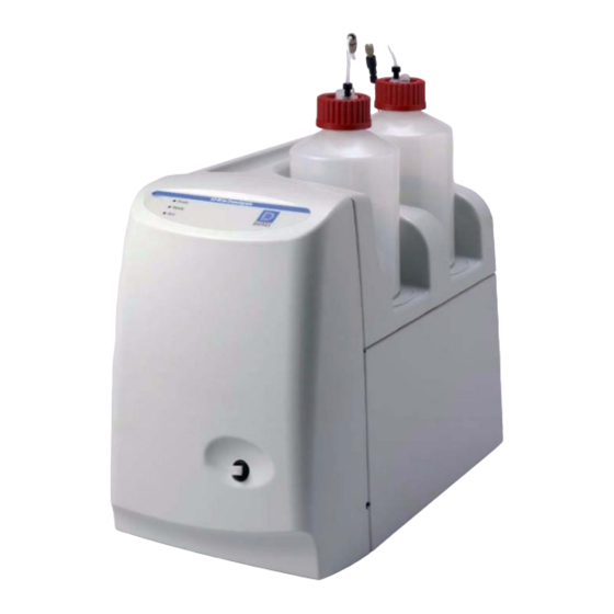
Figure 2-1 illustrates the front door and top cover of the ICS-90. The front door contains a sample injection port and LEDs that indicate the ICS-90 operating status. The top cover is molded to hold the eluent and regenerant reservoirs. LEDs There are three status LEDs on the ICS-90 front panel. - Page 19 2 • Description Eluent and Regenerant Reservoirs The ICS-90 top cover is molded to hold one eluent reservoir assembly (P/N 057711) and one regenerant reservoir assembly (anion, P/N 057712; cation, P/N 057713). • Eluent carries the sample through the ICS-90 and facilitates the ion separation process.
-
Page 20: Rear Panel
ICS-90 Ion Chromatography System 2.1.2 Rear Panel Figure 2-2 illustrates the ICS-90 rear panel. Figure 2-2. ICS-90 Rear Panel Power Switch The power switch provides on/off control of power to the ICS-90. Doc. 031851-05 12/04... - Page 21 The AC power outlet is located directly below the power switch. The power supply cord is used as the main disconnect device. Make sure the socket-outlet is located near the ICS-90 and is easily accessible. Le cordon d'alimentation principal est utilisé comme dispositif principal de débranchement.
- Page 22 The TTL output connector allows an AS40 Automated Sampler to receive TTL signals from the ICS-90. See Section B.17 for installation instructions. Tubing Connections Eight lines exit the ICS-90 from the lower left corner of the rear panel. These lines include: • 1 eluent line • 1 regenerant line •...
-
Page 23: Component Mounting Panel
Component Mounting Panel Figure 2-3 shows the user-accessible components installed inside the ICS-90. The component panel is accessed by opening the front panel door. All of the components that the user can service are located on this panel. DS5 Detection Stabilizer MMS™... - Page 24 Temperature compensation further improves baseline stability. Direct conductive heating is used in the ICS-90 to provide temperature control and compensation. A heat exchanger inside the ICS-90 cell regulates the temperature. All data is collected at 40 °C (104 °F).
- Page 25 2 • Description MMS III Suppressor The MMS III suppressor reduces the eluent conductivity and enhances the conductivity of the sample ions, thereby increasing detection sensitivity. As illustrated in Figure 2-5, a constant flow of regenerant over the membrane continually restores the suppression ability of the MMS III.
- Page 26 ICS-90 Ion Chromatography System accurate flow. Pressure limits are used to detect high or low pressure conditions that might require the pump to be shut down. The system backpressure should remain consistent. A significant increase in backpressure indicates a blockage in the liquid lines. A significant decrease in backpressure may indicate leaks or decreased pump flow due to an unprimed pump or insufficient eluent.
- Page 27 2 • Description Pump The ICS-90 uses a high-speed reciprocating pump with PEEK components. The flow rate can be set to between 0.5 and 4.5 mL/min. The recommended operating flow rate is between 0.5 and 2.0 mL/min. Prime Valve The prime valve is mounted on the pump head. The pump should be primed at installation and whenever the flow rate seems outside normal parameters.
-
Page 28: Fluid Schematic
ICS-90 Ion Chromatography System Fluid Schematic Figure 2-7 shows the flow path through the ICS-90 Ion Chromatography System. Figure 2-7. ICS-90 Flow Schematic Liquid flows through the ICS-90 along the following flow path: • Eluent from the eluent reservoir is pressurized by the gas, forced into the pump, and passes through the pressure transducer. -
Page 29: Displacement Chemical Regeneration (Dcr)
2 • Description • The eluent/sample mixture is pumped through the guard and separator columns, where the ions are separated by the ion exchange process (that is, different sample ions migrate through the columns at different rates, depending upon their interactions with the ion exchange sites). •... - Page 30 ICS-90 Ion Chromatography System Used eluent OUT to regenerant reservoir Regenerant IN from reservoir Regenerant OUT to waste Used Eluent Anion Regenerant W aste Figure 2-8. Anion ICS-90 Displacement Chemical Regeneration (DCR) 2-14 Doc. 031851-05 12/04...
-
Page 31: The Chromeleon Interface
• For automated control, you create a list of samples (a sequence) to be processed automatically. The sequence includes programs with commands and parameters for controlling the ICS-90, acquiring sample data, and producing reports. Section 3.5.5 describes automatic sample processing. -
Page 32: The Ics-90 Control Panels
ICS-90 Ion Chromatography System Figure 2-9. Chromeleon Browser 2.3.2 The ICS-90 Control Panels Chromeleon provides two kinds of Control panels for the ICS-90. System Control panels (see Figure 2-10) are used for controlling and monitoring ICS-90 operation. Wellness panels are used for performing calibration and diagnostic functions. - Page 33 2 • Description ICS-90 System Control panels contain the following information and controls. Sample Datasource Displays the database in which the chromatographic data for the sample is saved. Sequence Displays the sequence in which this sample is included. Sample Displays the name of the sample that is running.
- Page 34 On and Off buttons turn the pump on and off. Valve • Displays the position of the injection valve (LoadPosition or InjectPosition). • The Load and Inject buttons select the valve position. Plot Displays the ICS-90 detector signal plot. 2-18 Doc. 031851-05 12/04...
-
Page 35: Operation And Maintenance
ICS-90 Ship Kit. Preparing the Regenerant The type of regenerant used with the ICS-90 depends on the type of analysis to be run. A dilute sulfuric acid regenerant is used for anion analyses and a tetrabutylammonium hydroxide (TBAOH) regenerant is used for cation analyses. -
Page 36: Pressurizing The Eluent Reservoir
ICS-90 air regulator (see Figure 3-1). 2. Verify that the gas line from the eluent reservoir is connected to the ICS-90 air regulator outlet line. 3. Make sure the eluent and regenerant reservoirs are filled, the caps are tightly screwed onto the reservoirs, and the lines connecting the eluent and regenerant reservoirs to the ICS-90 lines are securely connected. -
Page 37: Preparing Samples
3 • Operation and Maintenance Do not pressurize the eluent reservoir above 70 kPa (10 psi). Ne mettez jamais les réservoirs d'éluants sous une pression supérieure à 0,07 MPa (10 lb/po²). Setzen Sie den Eluentbehälter auf keinen Fall einem Druck über 0,07 MPa (10 psi) aus. -
Page 38: Pretreating
Before injection, pretreat samples that may contain high concentrations of interfering substances by putting them through Dionex OnGuard™ cartridges. Refer to the Installation and Troubleshooting Guide for OnGuard Cartridges (Document No. 032943) for instructions. -
Page 39: Operation
4. Make sure the air regulator is adjusted to between 30 and 40 kPa (5 and 6 psi) (see Section 3.3). 5. Make sure the USB cable is connected to the USB port on the ICS-90 rear panel. See Section B.4 for installation instructions. -
Page 40: Starting Up Chromeleon
File menu to open it. Figure 3-2. Chromeleon Main Window and Browser 4. In the Browser, open the Dionex Templates\Panels\Dionex_IC\ICS- 90 System Panels folder and double-click one of the following ICS- 90 Control panels (depending on whether an AS40 autosampler will... -
Page 41: Preparing The Ics-90 For Operation
3 • Operation and Maintenance 5. Connect the ICS-90 to the Control panel by selecting Control>Connect to Timebase. Figure 3-3 is an example of the Dionex_ICS-90_System_AS40 Control panel. Figure 3-3. Chromeleon System Control Panel (ICS-90 with an AS40) 6. Check the Control panel for the following: •... -
Page 42: Manual Sample Processing
Control panel (see Figure 3-2). NOTE If the ICS-90 pump is running but no data is collected, the flow rate will remain constant indefinitely. However, if the ICS-90 receives no input from Chromeleon (you do not turn the pump on or off, run a sequence, toggle the injection valve position, etc.) for 6 hours after data is collected, the... -
Page 43: Automatic Sample Processing
For automated control, you create a list of samples (a sequence) to be processed automatically. For each sample, the sequence includes a program with commands and parameters for controlling the ICS-90, acquiring sample data, and generating reports. Additional sample processing parameters are included in the sequence (for example, the sample name, sample type, injection volume, etc.). -
Page 44: Sample Injection
S (5) on the injection valve (see Figure 3-4). 2. Fill the 1 cc syringe (P/N 016388) provided in the ICS-90 Ship Kit (P/N 059947) with a calibration standard or sample. 3. Insert the syringe into the injection port on the ICS-90 front door. - Page 45 Teflon® tubing). 2. Place the free end of the line into the sample. 3. Insert the 1 cc syringe (P/N 016388) provided in the ICS-90 Ship Kit (P/N 059947) into the injection port on the ICS-90 front door (see Figure 2-1) and pull the plunger out to “suck”...
- Page 46 Chromeleon Control panel (see Inject Figure 3-3) to start the injection. • For automatic sample processing (see Section 3.5.5), the Chromeleon program contains commands that start the AS40 sample load cycle and switch the ICS-90 injection valve position. 3-12 Doc. 031851-05 12/04...
-
Page 47: Maintenance
3 • Operation and Maintenance Maintenance This section describes routine maintenance procedures for the ICS-90 that users may perform. All other maintenance procedures must be performed by Dionex personnel. As Needed • Make fresh eluent as needed. • Regularly check the eluent reservoir to see if it needs to be refilled. - Page 48 ICS-90 Ion Chromatography System 3-14 Doc. 031851-05 12/04...
-
Page 49: Troubleshooting
The remaining sections in this chapter describe other operating problems and how to resolve them. If you are unable to eliminate a problem, contact Dionex for help. In the U.S., call Dionex Technical Support at 1-800-346-6390. Outside the U.S., call the nearest Dionex office. - Page 50 LOAD/INJECT VALVE ERROR If the injection valve fails to switch positions within 1 second of being toggled, the ICS-90 Moduleware will report an error to Chromeleon and the following error message will be displayed in the Audit Trail: Load/inject valve error.
- Page 51 4 • Troubleshooting • OVER CONDUCTIVITY This message usually appears for the first few minutes after the ICS-90 is started. If the message appears at other times, it indicates a problem. Conductivity exceeds limit. To troubleshoot: 1. Perform the suppressor QuickStart procedure: a.
-
Page 52: Liquid Leaks
• Leaking pressure transducer Make sure the liquid line connections into the pressure transducer are tight. Refer to Installation of Dionex Liquid Line Fittings (Document No. 031432) for tightening requirements. Replace any damaged fittings. • Leaking pump head waste valve Make sure the waste valve is closed. -
Page 53: Pump Difficult To Prime Or Loses Prime
4 • Troubleshooting • Leaking MMS III Refer to the suppressor manual for troubleshooting procedures. The suppressor manual is included on the Dionex Reference Library CD-ROM (P/N 055405), located in the ICS-90 Ship Kit. • Leaking injection valve Make sure the liquid line connections to the transducer are tight. Refer to Installation of Dionex Liquid Line Fittings (Document No. -
Page 54: Pump Does Not Start
• Restriction in the system plumbing Check all liquid lines for crimping or blockage. Make sure the ferrule fittings are not overtightened onto tubing. Refer to Installation of Dionex Liquid Line Fittings (Document No. 031432) for details. Doc. 031851-05 12/04... -
Page 55: Peak "Ghosting
B.14). • Clogged column bed supports Refer to the instructions in the column manual for troubleshooting guidance. The column manual is included on the Dionex Reference Library CD-ROM (P/N 055405), located in the ICS-90 Ship Kit. • Contaminated columns Clean the columns as instructed in the column manual. -
Page 56: Nonreproducible Peak Height Or Retention Time
• Contaminated column 1. Clean the column as instructed in the column manual. The column manual is included on the Dionex Reference Library CD-ROM (P/N 055405), located in the ICS-90 Ship Kit. 2. If cleaning is unsuccessful, replace the column. -
Page 57: No Ds5 Response
Section 4.1. Refer to the suppressor manual for additional troubleshooting guidance. The suppressor manual is included on the Dionex Reference Library CD-ROM (P/N 055405), located in the ICS-90 Ship Kit. • Sample concentration too high Dilute the sample (see Section 3.4.3). -
Page 58: Baseline Noise Or Drift
• Flow system leak; erratic baseline Check all fittings and liquid lines for leaks. Tighten or, if necessary, replace all liquid line connections. Refer to Installation of Dionex Liquid Line Fittings (Document No. 031432) for tightening requirements. • Trapped gases Release any trapped gases in the cell by loosening the lines to and from the cell and then retightening them. -
Page 59: Service
Chapter 4 isolate the cause of the problem. When ordering replacement parts, please include the ICS-90 model number and serial number. To contact Dionex in the U.S., call 1-800-346-6390. Outside the U.S., call the nearest Dionex office. Substituting non-Dionex parts may impair ICS-90 performance, thereby voiding the product warranty. - Page 60 Use the Wellness panel to monitor and/or perform the following functions: • System Status The check box to the left of the ICS-90 LED indicates the connectivity status. When the check box is gray, there is no connectivity between the ICS-90 and the Chromeleon computer.
- Page 61 5 • Service • Calibration Pressure Transducer • The offset, slope, and date of the last calibration are displayed. • The Measured field is in the slope calibration. See Section 5.1.1 for instructions. • The Calibrate Offset and Calibrate Slope buttons are used to calibrate the pressure transducer.
-
Page 62: Calibrating The Pressure Transducer
ICS-90 Control panel in Chromeleon. This removes any air or contaminant buildup in the injection valve loop. 1. Turn off the pump flow from the ICS-90 Control panel in Chromeleon. 2. Open the waste valve on the front of the pump head (see... - Page 63 Stabilizer Pressure Transducer Pump Head Waste Valve Figure 5-2. ICS-90 Interior Components 5. Close the waste valve. 6. Connect a pressure gauge between the pump outlet and the pressure transducer (see Figure 5-2). Turn on the pump and let the system stabilize.
-
Page 64: Calibrating The Cell
Use 0.076-mm (0.003-in) ID yellow PEEK at least 7 MPa (1000 psi) tubing (P/N 049715). 1. Open the ICS-90 Wellness panel in Chromeleon. To do this: a. In the Chromeleon Browser, expand the Dionex Templates folder, and then the Panels and the Wellness folder. - Page 65 After calibration, the conductivity reading should be 147.00 ± µ S/cm. If this is not the case, call Dionex for assistance. 12. Flush the KCl solution from the system by pumping DI water through the cell. When the conductivity drops to near zero, stop the pump flow.
-
Page 66: Replacing Tubing And Fittings
ICS-90 Ion Chromatography System Replacing Tubing and Fittings The ICS-90 is plumbed with the tubing and tubing assemblies listed below. Tubing Size and Type Used For 0.125-mm (0.005-in) ID PEEK Connection from pump pulse damper to (P/N 044221) injection valve 0.25-mm (0.010-in) ID PEEK... -
Page 67: Changing The Sample Loop
Figure 5-3. Injection Valve Plumbing 1. Turn off the pump from the ICS-90 Control panel in Chromeleon. 2. Open the ICS-90 front door. 3. Disconnect the sample loop from ports L and L on the injection valve (see Figure 5-3). -
Page 68: Isolating A Restriction In The Liquid Plumbing
Section B.13). If the pump does not stay primed, go to the next step. 2. Turn off the power switch on the ICS-90 rear panel and disconnect the power cord. 3. Open the front door of the ICS-90. 4. Disconnect the tube fittings from both the inlet and outlet pump check valve... - Page 69 Overtightening may damage the pump head or the check valve housing and crush the check valve seats. 9. Reconnect the liquid lines. Close the front door. 10. Reconnect the power cord, and turn on the power switch on the ICS-90. 11. Prime the pump (see Section B.13).
-
Page 70: Replacing A Pump Piston Seal
Flow rates will be unstable and there may be baseline noise. 1. Turn off the power switch on the ICS-90 rear panel and disconnect the power cord. 2. Open the ICS-90 front door. - Page 71 5 • Service 5. Slowly release the head, allowing it to separate from the housing. CAREFULLY disengage the head from the sapphire piston by pulling the head straight off and away from the mounting guides (see Figure 5-5). Be especially careful not to snap the piston if the internal spring sticks to the piston guide.
- Page 72 ICS-90 Ion Chromatography System Figure 5-7. Piston Assembly 13. Clean and inspect the piston. If it is scored or scratched, replace it (see Section 5.7). 14. Reinstall the retainer ring, spring retainer, piston, spring guide, and spring in the pump housing.
-
Page 73: Replacing A Pump Piston
Continued leaking from around the pump head after replacing the piston seal indicates a scratched or broken piston. 1. Turn off the power switch on the ICS-90 rear panel and disconnect the power cord. 2. Open the ICS-90 front door. - Page 74 ICS-90 Ion Chromatography System 9. Carefully slide the spring retainer onto the piston assembly. 10. Slide the assembled piston back into the piston housing. 11. Slide the spring over the piston, positioning it flush against the spring retainer. 12. Carefully slide the pump head straight onto the alignment rods. Guide the spring over the piston guide.
-
Page 75: Replacing The Waste Valve O-Ring
Replacing the Waste Valve O-Ring A damaged O-ring causes leakage around the base of the waste valve knob. 1. Turn off the pump from the ICS-90 Control panel in Chromeleon. 2. Open the front door of the ICS-90. 3. Turn off the gas pressure to the eluent reservoir. -
Page 76: Rebuilding The Injection Valve
NOTE Substitution of non-Dionex parts may impair valve performance and void the product warranty. 1. Turn off the pump from the ICS-90 Control panel in Chromeleon. 2. Open the front door of the ICS-90. 3. Disconnect each liquid line connected to the injection valve. -
Page 77: Installing A New Ds5 Detection Stabilizer
5 • Service 5.10 Installing a New DS5 Detection Stabilizer 1. Turn off the power on the ICS-90 rear panel and disconnect the power cord. 2. Open the ICS-90 front door. 3. Disconnect the line from the port on the... -
Page 78: Installing A New Suppressor
The suppressor manual is included on the Dionex Reference Library CD-ROM (P/N 055405), located in the ICS-90 Ship Kit. 1. Turn off the pump from the ICS-90 Control panel in Chromeleon. 2. Open the front door of the ICS-90. 3. Disconnect the four eluent and regenerant lines from the suppressor. -
Page 79: Changing The Main Power Fuses
1. Turn off the main power and disconnect the power cord. 2. The fuse holder is part of the main power receptacle on the ICS-90 rear panel. Note the recessed lock located on each side of the fuse holder (see Figure 5-10). - Page 80 3. Replace the two fuses in the holder with new IEC 127 fast-blow fuses rated 3.15 amps (P/N 054745). Dionex recommends always replacing both fuses. 4. Reinsert the fuse holder into its compartment. The fuse holder is keyed to fit only in its proper orientation.
-
Page 81: A • Specifications
A • Specifications A.1 Electrical Main Power Two voltage/frequency configurations (not user-selectable): 110–120 VAC/60 Hz 220–240 VAC/50 Hz 100 VAC/50 Hz Fuses Two fast-blow IEC 127 fuses rated 3.15 A (P/N 954745) A.2 Physical Dimensions Height without reservoirs: 32.125 cm (12.85 in) (with reservoirs Height with reservoirs and cap tubing: 59.63 cm (23.85 in) and tubing) -
Page 82: Environmental
Off: No power On: Power present • Ready Off: Not connected to Chromeleon On: System check passed and the ICS-90 is connected to Chromeleon Flashing: System check failed (occurs if system check executes for 10 minutes without success) • Off: Not running... -
Page 83: Rear Panel
Link LED The Link LED displays the communication status between the ICS-90 and Chromeleon: Off: There is no communication link between the ICS-90 and Chromeleon. On: The communication link between the ICS-90 and Chromeleon is activated, but data is not being transmitted or received. -
Page 84: Detector
ICS-90 Ion Chromatography System A.8 Detector Digital signal range of 0 to 1000 µS Range Temperature Preset for accurate reading at 40 ºC Compensation Cell Drive 8 kH square wave -999 to 999 µS Auto Offset Control and Provided by Chromeleon software. Communication with the ICS- Data Evaluation 90 is via USB (Universal Serial Bus). -
Page 85: B • Installation
• Allow at least 15 cm (6 in) behind the ICS-90 for power connections and ventilation. For optimal performance, install the ICS-90 in a draft-free location, out of the path of air conditioning and heating vents. -
Page 86: Unpacking The Ics-90 System
3. Remove the foam cover. 4. Using the cardboard side handles, carefully remove the ICS-90 from the box. You may need to remove the foam at the sides of the ICS-90 before you can lift the instrument from the box. -
Page 87: Removing The Pump Shipping Screw
B.2.2 Removing the Pump Shipping Screw 1. Carefully lay the ICS-90 on its back or side. 2. Locate the middle screw on the bottom of the ICS-90 (see Figure B-1). This screw secures the pump in place during shipment. 3. Use a Phillips screwdriver to remove the shipping screw. -
Page 88: Unpacking The Computer (North America Only
Unpacking the Computer (outside North America) 1. Refer to Installing the Chromeleon Chromatography Management System with a Dionex Ion Chromatograph (Document No. 031883) to verify that the computer being used meets Chromeleon specifications. 2. Remove the central processing unit (CPU), keyboard, mouse, and all documentation from the computer box and place these items on a workbench. -
Page 89: Installing Chromeleon
B • Installation B.3 Installing Chromeleon NOTES • Windows 2000 is required for controlling the ICS-90. • To install Chromeleon, you must log onto Windows 2000 with administrator or power user privileges. Administrator privileges are not required to run Chromeleon. -
Page 90: Connecting The Ics-90 To The Computer
Figure B-4) provides a USB receptacle for connecting the ICS-90 to a USB port on the Chromeleon PC or a USB hub. Before connecting the USB cable and turning on the ICS-90 power, verify that Chromeleon is installed on the PC (see Section B.3). - Page 91 Figure B-3. Example Connections: One ICS-90 Connected to the Computer 3. If there are no unused USB ports on the PC, connect the ICS-90 to an external USB hub (P/N 060392) and connect the Chromeleon PC to the hub (see Figure B-4).
-
Page 92: Connecting The Power Cord
(32 yds) from the PC. B.5 Connecting the Power Cord 1. A label on the ICS-90 rear panel indicates the line frequency (60 Hz or 50 Hz) and voltage (110 to 120 VAC or 220 to 240 VAC) for which the system is designed. -
Page 93: Turning On The Ics-90 Power
1. Turn on the computer power. Log onto Windows 2000 as an administrator or power user. 2. Turn on the power to the ICS-90. Windows 2000 automatically detects the new USB device. A message flashes on the screen to inform you that the device was detected. -
Page 94: Setting Up Chromeleon
B.7.1 Installing the Chromeleon Software License For the Chromeleon computer to control the ICS-90, a valid software license must be installed. To install the license, you first install a dongle on the computer and then enter a license “Key Code” in Chromeleon. (A dongle is an adapter that is connected to the parallel PC interface or USB port. - Page 95 B • Installation • If Chromeleon was not pre-installed, the Server Monitor status displays “Chromeleon Server is running idle (Evaluation Mode).” (see Figure B-5) If this is the case, go on to Step 3. Figure B-5. Server Evaluation Mode 3. Open the Chromeleon Server Configuration program (select Start>Chromeleon>Server Configuration).
-
Page 96: Creating A Timebase
ICS-90 Ion Chromatography System 5. Check the Server Monitor status. It should now display “Chromeleon Server is running idle.” (see Figure B-7). Figure B-7. Server Running 6. Click to close the Server Monitor window. Close B.7.2 Creating a Timebase 1. In the Server Configuration program, select Edit>Add Timebase. - Page 97 3. Select Edit>Add Device. The Add device to timebase dialog box appears. Figure B-9. Add Device Dialog Box 4. Select Dionex ICS-90 System from the list and click OK. A dialog box appears. Figure B-10. ICS-90 Configuration Properties: Live Mode B-13 Doc.
-
Page 98: Connecting The Ics-90 To A Chromeleon Control Panel
5. On the General tab page, Live Mode is selected by default. Select the ICS-90 serial number from the drop-down list. If you are installing more than one ICS-90, you can verify the serial number for each ICS-90 by checking the label at the top of the component panel (see Figure B-19). -
Page 99: In The Browser, Open The Dionex Templates\Panels\Dionex_Ic\Ics
Dionex_ICS-90_System_AS40 3. If a “Cannot connect to timebase…” message appears, click OK to close it. NOTE If the timebase was named “ICS-90” when it was created, the Control panel opens and connects automatically to the ICS-90 timebase. 4. If the Control panel opens with the controls not yet active (see... - Page 100 ICS-90 Ion Chromatography System 5. A dialog box appears (see Figure B-13). Figure B-13. Connect to Timebase 6. Click the ‘+’ sign beside My Computer on the right side of the dialog box and select the timebase you created in Section B.7.2.
-
Page 101: Verifying Chromeleon Communication
B • Installation B.7.4 Verifying Chromeleon Communication Verify that Chromeleon is communicating with the ICS-90 by clicking the and then the button on the Control panel, while Disconnect Connect observing the ICS-90 front panel LEDs. If Chromeleon and the ICS-90 are communicating correctly, the... -
Page 102: Connecting The Waste Lines
ICS-90 Ion Chromatography System B.8 Connecting the Waste Lines Untape the coiled waste and liquid lines from the rear panel. Place the ends of the three waste lines into a waste container. The waste lines siphon off prime waste from the pump head, sample overflow from the injection valve, and system waste from the suppressor. -
Page 103: Connecting The Gas Source
B.9 Connecting the Gas Source 1. Locate the barbed fitting (P/N 030071), pipe thread reducer (P/N 030087), 1/8-in ID tubing (P/N 040793), and ICS-90 air regulator accessory (P/N 060054) in the ICS-90 Ship Kit. 2. Use the barbed fitting and pipe thread reducer to connect the 1/8-in ID tubing to a clean gas source, regulated to between 0.55 and 0.83 MPa (80 and... -
Page 104: Setting Up The Eluent And Regenerant Reservoirs
The regenerant reservoir must be filled all the way to the top at all times. e. Insert the stopper assembly tubing into the reservoir and tighten the stopper. Do not shake the regenerant reservoir to mix the contents. The ICS-90 will stratify the contents. B-20 Doc. 031851-05 12/04... - Page 105 6. Install the caps on the eluent and regenerant reservoirs and hand tighten. 7. Place the reservoirs in the holders on the top cover of the ICS-90. 8. Connect the liquid lines from the ICS-90 to the lines exiting the eluent and regenerant reservoir caps (see...
-
Page 106: Installing And Plumbing The Columns And Suppressor
For flow rates of 2 mL/min or more, remove one of the backpressure coils. NOTE Refer to the flier Backpressure Coil Pressure Test for Dionex Suppressors (Document No. 031759) (shipped with the suppressor) for details about suppressor operating pressure requirements. - Page 107 Cell Out Union Do not Verify that 1 remove or 2 back- pressure coils are installed (not shown in photo) Column In/Out Union (remove) Guard In/Out Union (remove) Figure B-19. ICS-90 Component Panel (Door not shown) B-23 Doc. 031851-05 12/04...
- Page 108 Guard Column line Figure B-20. ICS-90 with Columns and Suppressor Installed 4. To ensure the correct operating pressure for the suppressor, either one or two backpressure coil(s) (P/N 045877) must be installed between the cell outlet and the regenerant reservoir inlet. The number of coils required depends upon...
-
Page 109: Pressurizing The Eluent Reservoir
For flow rates of 2 mL/min or more, remove one of the backpressure coils. NOTE Refer to the flier Backpressure Coil Pressure Test for Dionex Suppressors (Document No. 031759) (shipped with the suppressor) for details about suppressor operating pressure requirements. -
Page 110: Priming The Pump
Section B.14 to set the flow rate for your application. 6. Turn on the pump from the ICS-90 Control panel in Chromeleon. Allow the pump to run with the waste valve open for 30 seconds. 7. Close the waste valve knob. - Page 111 B • Installation Pulse Damper Pump Head Waste Valve Pump Flow Rate Knob Figure B-21. ICS-90 Interior Components B-27 Doc. 031851-05 12/04...
-
Page 112: Setting The Pump Flow Rate
ICS-90 Ion Chromatography System B.14 Setting the Pump Flow Rate 1. Locate the production test chromatogram on the Dionex Quality Assurance Report (supplied with the separator column). Note the backpressure and flow rate listed for the column. 2. Pull out the flow rate knob on the component mounting panel (see... - Page 113 B • Installation Volumetric Method 1 (Recommended): Using a Syringe and Adapter a. Locate the following items in the ICS-90 Ship Kit: luer fitting (P/N 024305), luer coupler (P/N 042806), 1 mL syringe (P/N 016388), and 10 mL syringe (P/N 016387). You will also need a stopwatch or a clock or watch with a second hand (the computer’s clock can be used),...
- Page 114 ICS-90 Ion Chromatography System Volumetric Method 2: Using a Graduated Cylinder a. Disconnect the line from the port on the ELUENT IN ELUENT IN suppressor. b. Using a clock or watch with a second hand (the computer’s clock can be...
-
Page 115: Record The Measured Flow Rate In Chromeleon
Control>Command. 2. Expand the Pump_ECD group and select MeasuredFlowRate (see Figure B-23). Figure B-23. ICS-90 Chromeleon Commands: MeasuredFlowRate 3. Enter the flow rate and click Execute. Click Close. The measured flow rate is now shown on the Control panel. B-31... -
Page 116: Equilibrating The System
ICS-90 Ion Chromatography System B.15 Equilibrating the System 1. After priming the pump and adjusting the flow rate, leave the pump on and flush the system for about 5 minutes to equilibrate. 2. Monitor the system pressure from the Control panel to make sure the pressure is between 107 and 153 MPa (1600 and 2300 psi). -
Page 117: Connecting The As40 Automated Sampler (Optional
B • Installation B.17 Connecting the AS40 Automated Sampler (Optional) 1. Open the front door of the ICS-90 and thread the outlet line from the AS40 through the side slot near the lower ICS-90 door hinge (see Figure B-20). 2. Connect the outlet line from the AS40 to port S (5) of the injection valve (see Figure B-24). -
Page 118: Operating The Ics-90
3.5. B.19 Installation Troubleshooting Problem: When the ICS-90 power is turned on for the first time, a Windows message box appears asking for a USB configuration file (cmwdmusb.inf). Possible Cause: The USB cable was connected and the power turned on before Chromeleon was installed. -
Page 119: C • Reordering Information
C • Reordering Information Part Number Item Pump 057853 Pump head assembly 055870 Main piston seal 036901 Backup piston seal 035776 O-ring 047661 Outlet check valve assembly, 10-32 047660 Inlet check valve assembly, 1/4-28 057233 Backup washer assembly 035030 Piston guide 036904 Piston 035014... - Page 120 ICS-90 Ion Chromatography System Part Number Item Reagent Reservoir Assemblies 057711 Eluent reservoir assembly (includes stopper and cap) 057712 Anion regenerant reservoir assembly (includes stopper and cap) 057713 Cation regenerant reservoir assembly (includes stopper and cap) 059068 O-ring for eluent or regenerant reservoir stopper...
-
Page 121: D • Faq
D • FAQ D.1 How do I hook up an AS40 Automated Sampler? For instructions on how to connect the ICS-90 to an AS40, see Section B.17 this manual. Also see the AS40 Automated Sampler Operator’s Manual (Document No. 034970). -
Page 122: D.6 When Should I Remake Standards?
D.11 How do I shut off the system? In Chromeleon, turn off the pump from the ICS-90 Control panel (see Figure 2-10). On the ICS-90, turn off the power switch on the rear panel (see Figure 2-2). D.12 How do I store columns? Columns should be stored in eluent. -
Page 123: D.13 How Do I Know When A Column Is Dirty?
D.13 How do I know when a column is dirty? See the troubleshooting section of the column manual. The column manual is included on the Dionex Reference Library CD-ROM (P/N 055405), located in the ICS-90 Ship Kit. D.14 How do I clean a column? See the troubleshooting section of the column manual. - Page 124 ICS-90 Ion Chromatography System Doc. 031851-05 12/04...
- Page 125 E • Glossary Analytical Column Synonymous with Separator Column. Band Spreading The broadening of the sample band as it travels through the column. Band spreading can also occur in the injection valve, detector cell, and interconnecting tubing. Calibration Curve A graph showing detector response in peak height or area versus analyte concentration.
- Page 126 ICS-90 Ion Chromatography System The value of k depends upon the surface area of, and distance between, the electrode faces in the conductivity detector cell. l A ⁄ Where: l = length A = area of one electrode (the other electrode is equal to...
- Page 127 E • Glossary contained between two opposite charged electrodes. Conductivity is a characteristic of ions in solution. Units are siemens. Counterion Ions carrying a charge opposite that of the sample ions (e.g., Na ) may be the counterion of a Cl analyte.
- Page 128 ICS-90 Ion Chromatography System Pellicular Resin A resin with a solid, nonporous core coated with a thin layer of more porous material. The exchange sites of pellicular ion exchange resins are located only on the surface layer of the bead. These resins have a low ion-exchange capacity.
- Page 129 E • Glossary Suppressor A device used to minimize eluent conductivity and convert sample species to a common form, thus increasing detection sensitivity. Temperature Coefficient The percent of change in the conductivity of a solution with a 1 C change in temperature.
- Page 130 ICS-90 Ion Chromatography System Doc. 031851-05 12/04...
- Page 131 Chromeleon Auto offset requirements, A-4 Alarm conditions, 4-1 Autozero, 2-17, 3-8 Browser, 2-15 Communication with ICS-90, 2-5 Error conditions, 4-1 ICS-90 Control panel, 2-15, 3-8 Interface, 2-15 Background conductivity License, B-10 High, 4-3, 4-9 Menu, 2-15, 3-8 Offsetting, 3-7, 3-10...
- Page 132 Cell body, A-4 Prime valve, 2-11 Electrodes, A-4 Pump, 2-11 Maximum pressure, A-4 Computer Dummy cell, 4-9, 5-3 Connecting to the ICS-90, B-6 Unpacking, B-4 Conductivity, 2-17 Causes of high conductivity, D-3 Temperature effect, 2-8 See Electrochemical detector conductivity Conductivity cell, 2-7...
- Page 133 Rear panel, 2-4 Status, 2-2 Top cover, 2-2 License (Chromeleon), B-10 Weight, B-2 Lifting the ICS-90, B-2 ICS-90 Control panel (Chromeleon), 2-15, 3-8 Line frequency, B-8 Important icon, 1-5 Linearity requirements, A-4 Injecting sample Link LED, 2-5, A-3 Syringe injection, 3-10...
- Page 134 ICS-90 Ion Chromatography System Loop, 2-10 Front panel, 2-2 Changing, 5-9 Rear panel, 2-4 Parameters, 2-15, 3-9 Peak ghosting, 4-7 Peak height Troubleshooting, 4-8 Main power receptacle, 2-5 PEEK cell body, 2-7 Maintenance, 3-13 Physical specifications Daily, 3-13 Decibel level, A-1...
- Page 135 Index Pump head waste valve Leaking, 4-4 Safety labels, 1-7 Pump specifications Safety messages and icons, 1-5 – 1-6 Flow rate, A-3 Sample injection Operating pressure, A-3 AS40 injection, 3-12 Operation mode, A-3 Via syringe, 3-10 Type, A-3 Via vacuum syringe, 3-11 Sample loop, 2-10 Changing, 5-9 Injecting, 2-10...
- Page 136 ICS-90 Ion Chromatography System Detector, A-4 Error conditions, 4-1 DS5 Detection Stabilizer, A-4 Excessive backpressure, 4-6 Electrical, A-1 Flow rate, 4-6 Environmental, A-2 High DS5 output, 4-9 Injection valve, A-4 Liquid leaks, 4-4 Physical, A-1 No DS5 response, 4-9 Pump, A-3...
- Page 137 Index Waste valve O-ring Replacing, 5-17 Water samples, 3-4 Weight, A-1 Wellness panel, 5-1 Audit Trail, 5-2 Calibrations, 5-3 Diagnostics, 5-3 Dummy cell, 5-3 ECD conductivity, 5-2 System pressure, 5-2 System status, 5-2 Zeroing the baseline At injection, 3-10 Index-7 Doc.
- Page 138 ICS-90 Ion Chromatography System Index-8 Doc. 031851-05 12/04...
Need help?
Do you have a question about the ICS-90 and is the answer not in the manual?
Questions and answers