
Subscribe to Our Youtube Channel
Related Manuals for Dionex ICS-900


Summary of Contents for Dionex ICS-900
- Page 1 ICS-900 Ion Chromatography System Operator’s Manual Document No. 065215 Revision 02 September 2009...
- Page 2 Dionex Corporation, 1228 Titan Way, Sunnyvale, California 94088-3603 U.S.A.
-
Page 3: Table Of Contents
Overview of the ICS-900 ........ - Page 4 Operation Overview ........27 Turning On the ICS-900 Power .......28 Connecting to Chromeleon or Chromeleon Xpress .
- Page 5 Contents 3.11.4 Loading and Injecting Samples with an Autosampler ..44 3.11.5 Loading and Injecting Samples with a Syringe ... . 46 3.11.6 Example Chromeleon Commands for Loading and Injecting Samples .
- Page 6 ICS-900 Operator’s Manual 5.1.2 Wellness Panel Features ......67 5.1.3 Calibrating the Pressure Transducer .....69 5.1.4...
- Page 7 Contents Suppressors ..........95 Column Heater/Thermostat .
- Page 8 ICS-900 Operator’s Manual How do I delete data? ........114 D.10 How do I shut off the system? .
-
Page 9: Introduction
Dionex chromatography instruments, but does not include data management capabilities. For communication between the ICS-900 and the PC on which Chromeleon or Chromeleon Xpress is installed, the ICS-900 must be connected to a USB (Universal Serial Bus) port on the PC or a USB hub. For details, refer to the ICS-900 Ion Chromatography System Installation Instructions (Document No. -
Page 10: The Ics-900 Operator's Manual
ICS-900 Operator’s Manual The ICS-900 Operator’s Manual 1.2.1 Overview The electronic version (i.e., PDF file) of the ICS-900 operator’s manual contains numerous hypertext links that can take you to other locations within the file. These links include: • Table of contents entries •... -
Page 11: Safety And Regulatory Information
527 Lakeside Drive, Sunnyvale, CA 94088-3603 U.S.A. The ICS-900 is designed for IC (ion chromatography) applications and should not be used for any other purpose. Operation of an ICS-900 in a manner not specified by Dionex may result in personal injury. - Page 12 ICS-900 Operator’s Manual Indicates a potentially hazardous situation which, if not avoided, may result in minor or moderate injury. Also used to identify a situation or practice that may seriously damage the instrument, but will not cause injury. Indicates that the function or process of the instrument may be impaired.
-
Page 13: Safety Symbols
1.3.2 Safety Symbols These symbols appear on the ICS-900 or on ICS-900 labels: Alternating current Primary protective conductor terminal Secondary protective conductor terminal Power supply is on Power supply is off Indicates a potential hazard. -
Page 14: Declaration Of Conformity
ICS-900 Operator’s Manual 1.3.3 Declaration of Conformity The cETLus and CE marks on the ICS-900 model/data label indicate that the ICS-900 is in compliance with the following standards. Doc. 065215-02 9/09... -
Page 15: Description
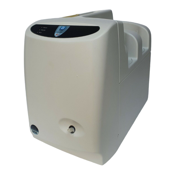
2 • Description Operating Features 2.1.1 Front Door and Top Cover Figure 2-1 illustrates the front door and top cover of the ICS-900 Ion Chromatography System (ICS-900). Eluent Bottle Regenerant Bottle Status LEDs Injection Port Figure 2-1. ICS-900 Ion Chromatography System... - Page 16 Injection Port The injection port can be connected to the injection valve inside the ICS-900. The sample to be analyzed is injected into the injection port using a syringe. For automated sample injections, the ICS-900 injection valve can be connected to an autosampler, instead of to the injection port.
-
Page 17: Component Mounting Panel
2 • Description performed. For example, an ICS-900 configured for anion analyses uses carbonate eluent, while an ICS-900 configured for cation analyses uses methanesulfonic acid (MSA) eluent. • Regenerant renews the suppressor’s ability to suppress eluent conductivity. An ICS-900 configured for anion analyses uses dilute sulfuric acid regenerant. - Page 18 Pump Heads The ICS-900 includes a dual-piston serial pump. The flow rate can be set from 0.01 mL/min to 5.00 mL/min. However, for optimum performance, set the flow rate to between 0.20 and 3.00 mL/min. Setting the flow rate to 0.00 mL/min turns off the pump.
-
Page 19: Rear Panel
Chromeleon or Chromeleon Xpress is installed. For the standard system configuration of one ICS-900 connected to a PC, connect a USB cable between the USB connector on the ICS-900 and a USB port on the PC. For detailed connection instructions, refer to the ICS-900 Ion Chromatography System Installation Instructions (Document Doc. - Page 20 ICS-900 and the PC on which Chromeleon or Chromeleon Xpress is installed. LED Status Description The ICS-900 and the PC are linked, but no data is currently being transmitted or received Flashing The ICS-900 and the PC are linked and data is being...
- Page 21 Stellen Sie sicher, daß sich die Steckdose nahe am Gerät befindet und leicht zugänglich ist. Plumbing and Waste Lines The following lines exit the ICS-900 through the tubing chase on the lower left corner of the rear panel. • Eluent •...
-
Page 22: Fluid Schematic
ICS-900 Operator’s Manual Fluid Schematic Figure 2-4 shows the flow path through the ICS-900. From cell outlet To pump inlet Backpressure Coil Regenerant (1 or 2, depending on flow rate) Eluent Conductivity Cell (in DS5 Detection Stabilizer) To cell inlet... - Page 23 2 • Description Liquid flows through the ICS-900 along the following flow path. Refer to Figure 2-4 for the flow path number locations. • Eluent from the eluent bottle is drawn into the pump . The pump pushes the eluent through the pressure transducer , which measures the system pressure, and through a pulse damper , which smooths minor pressure variations from the pump to minimize baseline noise.
-
Page 24: System Component Details
ICS-900 Operator’s Manual System Component Details 2.3.1 Pump The ICS-900 pump is a microprocessor-based isocratic eluent delivery system. Its variable speed, dual-piston series design ensures pulse-free pumping for the most demanding applications. Primary Pump Head The primary pump head pumps eluent into the secondary head (see Figure 2-5). -
Page 25: Pressure Transducer
2 • Description 2.3.2 Pressure Transducer The pressure transducer measures the system pressure at the point that the eluent flows from the pump head outlet check valve. Pressure readings indicate that the pumping system is delivering smooth, accurate flow. Pressure readings can be monitored from Chromeleon or Chromeleon Xpress. -
Page 26: Injection Valve With Sample Loop
ICS-900 Operator’s Manual 2.3.3 Injection Valve with Sample Loop The injection valve is a six-port, electrically-activated Rheodyne valve. A 10 μL sample loop (P/N 042949) is installed on the valve at the factory. The valve has two operating positions: Load and Inject. Eluent flows through either the Load or Inject path, depending on the valve position. -
Page 27: Mms 300 Micromembrane Suppressor
See Section 2.3.5 for details. For more information about the MMS 300, refer to the suppressor manual. Suppressor manuals are included on the Dionex Reference Library CD- ROM (P/N 053891). Figure 2-7. MMS 300 Suppressor Flow Doc. 065215-02 9/09... -
Page 28: Displacement Chemical Regeneration (Dcr)
(in DS5 Detection Stabilizer) Anion Eluent Regenerant out to cell Regen Out Eluent Out Regenerant in AMMS 300 from reservoir Regen In Eluent In Eluent in from column Regenerant out to waste Figure 2-8. Anion ICS-900 Displacement Chemical Regeneration (DCR) Doc. 065215-02 9/09... -
Page 29: Conductivity Cell And Ds5 Detection Stabilizer
(anion regenerant bottle assembly, P/N 068222; cation regenerant bottle assembly, P/N 068223). For detailed installation instructions, refer to the DCR Kit Installation Instructions (Document No. 031664), provided on the Dionex Reference Library CD- ROM (P/N 053891). 2.3.6... - Page 30 Direct conductive heating is used in the ICS-900 conductivity cell to provide temperature control and compensation. A heat exchanger inside the ICS-900 cell regulates the temperature. All data is collected at 40 °C (104 °F). The cell is housed inside a DS5 Detection Stabilizer (P/N 067761) (see...
-
Page 31: Chromeleon And Chromeleon Xpress Software
An ICS-900 Control panel (see Figure 2-11) provides access to ICS-900 functions. The label on the tab for this panel is the name of the timebase in which the ICS-900 is configured. Figure 2-11. ICS-900 Panel on the Panel Tabset... -
Page 32: Software Control Modes
A Status panel shows the overall system status. • An autosampler panel provides access to autosampler functions. This panel is present only if the timebase in which the ICS-900 is configured includes an autosampler. To open the panel tabset, use one of the methods below: •... -
Page 33: System Wellness And Predictive Performance
Predictive Performance provides functions for monitoring the usage of replaceable parts and for planning service procedures. Predictive Performance lets you monitor the following functions: • The number of hours the ICS-900 has been in use • The number of times the injection valve has cycled •... - Page 34 ICS-900 Operator’s Manual (InjectValveCycles, PumpPistonStrokes, SealWear, SuppressorVolume, ColumnVolume) (see Figure 2-12). Figure 2-12. Predictive Performance Commands: InjectValveCycles If you do not wish to receive these warning or error messages, you can disable them by setting the Warning and Limit parameter for each Predictive Performance function to Off.
-
Page 35: Operation And Maintenance
3 • Operation and Maintenance This chapter describes routine operating and maintenance procedures for the ICS- 900 Ion Chromatography System (ICS-900). Operation Overview Figure 3-1 illustrates the basic steps for routine operation of the ICS-900. Turn on the ICS-900 power Connect to Chromeleon... -
Page 36: Turning On The Ics-900 Power
Default Panel Tabset toolbar button. If Chromeleon Xpress is installed, starting the application automatically displays the panel tabset. 5. To display the ICS-900 Control panel, select the tab labeled with the ICS-900 timebase name (see Figure 3-2). Doc. 065215-02 9/09... -
Page 37: Preparing The Eluent
The ICS-900 determines the eluent usage by monitoring the flow rate and the length of time the pump is on. As the eluent is used up, the ICS-900 updates the slider and gauge. A warning appears in the Audit Trail when Eluent Remaining the level falls below 200 mL, and then again when the level falls bellow 100 mL. -
Page 38: Preparing The Regenerant
Figure 3-3. Setting the Eluent Level Preparing the Regenerant The type of regenerant used with the ICS-900 depends on the type of analysis to be run. A dilute sulfuric acid regenerant is used for anion analyses; a tetrabutylammonium hydroxide (TBAOH) regenerant is used for cation analyses. - Page 39 6. Fill the bottle almost to the top with deionized water and then place the bottle in the tray on the top of the ICS-900. NOTE To avoid staining the ICS-900, be careful not to spill TBAOH on the instrument.
-
Page 40: Priming The Pump
After the analysis begins, do not mix the contents of the regenerant bottle. 10.Verify that the liquid lines from the bottles are ELUENT REGEN connected to the corresponding lines from the ICS-900 (see Figure 3-4). ELUENT Bottle Out REGEN REGEN Bottle Out Bottle In Figure 3-4. - Page 41 Commands dialog box (press F8), select the Pump command, and select the Prime option. The pump will begin pumping at approximately 3 mL/min. 5. Continue priming the ICS-900 until no air bubbles are exiting the pump waste line. 6. Click Pump Off 7.
- Page 42 ICS-900 Operator’s Manual Priming the Eluent Line with a Syringe (Optional) A syringe can be used to facilitate priming when the eluent line is empty or the pump heads are completely dry. 1. Verify that the pump is turned off.
-
Page 43: Equilibrating The System
Equilibrating the System 1. Turn on the pump and run at the flow rate recommended for the column. 2. Allow the system to equilibrate. The ICS-900 Control panel displays the background conductivity (the conductivity of the eluent without the offset performed by the autozero command). -
Page 44: Configuring Standby Mode
ICS-900 Operator’s Manual Configuring Standby Mode You can configure the ICS-900 to enter standby mode after a period of inactivity (a period of time in which no data collection and no input from Chromeleon or Chromeleon Xpress has occurred). In standby mode, the pump flow rate is reduced. -
Page 45: Preparing Samples
Filter groundwater and wastewater samples through 0.45 μm filters before injection, unless samples were filtered after collection. A Dionex High Pressure Inline Filter (P/N 044105) is available for removing particulates down to 0.45 micron from samples. Connect the inline filter between the autosampler outlet and the sample inlet port on the injection valve. -
Page 46: Diluting
For instructions, refer to Installation and Troubleshooting Guide for OnGuard Cartridges (Document No. 032943). The manual is included on the Dionex Reference Library CD-ROM (P/N 053891). 3.10.3 Diluting Because the concentrations of ionic species in different samples can vary widely from sample to sample, no single dilution factor can be recommended for all samples of one type. -
Page 47: Processing Samples
3 • Operation and Maintenance 3.11 Processing Samples 3.11.1 Overview Samples can be run manually (one at a time), or they can be grouped and run automatically in batches. Figure 3-8 shows the typical steps for manual and batch sample processing. Manual Sample Batch Sample Processing... -
Page 48: Manually Processing Samples
3.11.4) or a syringe (see Section 3.11.5). 6. The signal plot is displayed on the ICS-900 Control panel (see Figure 3-9). Monitor the chromatogram and when sample data has been collected, click the Acq Off button on the Sequence Control... - Page 49 3 • Operation and Maintenance panel (or click the Acquisition On/Off button on the Chromeleon toolbar). Figure 3-9. Manual Data Acquisition Saving Manual Data NOTE Chromeleon Xpress does not allow data to be saved. If you are using Chromeleon, data from manual processing is saved in the manual sequence under the timebase folder in the local datasource.
-
Page 50: Automatically Processing Samples (Batch Processing)
Autosampler manuals are provided on the Dionex Reference Library CD-ROM (P/N 053891). 3. If an autosampler is not installed, load the sample into the injection valve sample loop through the sample port on the ICS-900 front door (see Section 3.11.5). - Page 51 3 • Operation and Maintenance b. Select an application template from the list (see Figure 3-10). Figure 3-10. Application Wizard c. Click Next> and select the in a new sequence via Sequence Wizard option. d. Click Next> to go to the Sequence Wizard. e.
-
Page 52: Loading And Injecting Samples With An Autosampler
The manuals are included on the Dionex Reference Library CD-ROM (P/N 053891). The ICS-900 Installation Instructions are also included in the ICS-900 Ship Kit (P/N 067768). 2. Prepare and fill the sample vials and place them in the autosampler tray or cassette. - Page 53 3 • Operation and Maintenance Autosampler Setup Notes Follow the steps below to verify that the ICS-900 injection valve is controlled by the correct device. 1. Open the Chromeleon Server Configuration program. 2. Open the ICS-900 Properties dialog box and click Inject Valve.
-
Page 54: Loading And Injecting Samples With A Syringe
Section 3.11.4. Loading Samples with a Syringe (Push Method) 1. Verify that the sample loading port on the front of the ICS-900 is connected to sample port on the injection valve (see S (5) Figure 3-14). - Page 55 3 • Operation and Maintenance Loading Samples with a Vacuum Syringe (Pull Method) 1. Verify that the sample loading port on the front of the ICS-900 is connected to sample port on the injection valve (see S (5) Figure 3-14).
-
Page 56: Example Chromeleon Commands For Loading And Injecting Samples
ICS-900 Operator’s Manual 6. Use one of the following methods to inject the sample onto the column: • Manually: click the Inject button on the ICS-900 Control panel. Section 3.11.2 for details about manually processing samples. • Automatically: Include the Inject command in a Chromeleon or Chromeleon Xpress program. -
Page 57: Maintenance
4. Switch the valve to Inject for 30 seconds. 5. Stop data acquisition. 3.12 Maintenance This section describes routine maintenance procedures for the ICS-900 that users may perform. All other maintenance procedures must be performed by Dionex personnel. As Needed •... - Page 58 For instructions on how to replace the sampling tip, see the AS40 Automated Sampler Operator’s Manual (Document No. 034970). The manual is included on the Dionex Reference Library CD-ROM (P/N 053891). Doc. 065215-02 9/09...
-
Page 59: Troubleshooting
Section 4.13 describe other operating problems and how to resolve them. If you are unable to eliminate a problem, contact Dionex for help. In the U.S., call Dionex Technical Support at 1-800-346-6390. Outside the U.S., call the nearest Dionex office. - Page 60 56 The system pressure has exceeded the high pressure limit. Conductivity exceeds limit. This message may appear at when the ICS-900 power is turned on. If the message appears at other times, it indicates a problem. To troubleshoot: 1. Perform the suppressor inline quick start procedure: a.
-
Page 61: Flow Rate Calibration Error
1 mL/min. For flow rate calibration instructions, see Section 5.1.5. Load/inject valve error. If the injection valve fails to switch positions within 1 second of being toggled, the ICS-900 Moduleware reports an error to Chromeleon or Chromeleon Xpress and this error message is displayed. Doc. 065215-02 9/09... -
Page 62: Module Data Buffer Overflow. Data May Have Been Lost
1. If a sequence is being executed, terminate the sequence by selecting Stop on the Batch menu. 2. Turn off the ICS-900 power briefly and then restart. 3. Try to toggle the valve from Load to Inject by clicking the Inject button on the ICS-900 Control panel. -
Page 63: Pump Pressure Slope Calibration Error
For the eluent level to be accurate, you must enter the level on the ICS-900 Control panel each time the bottle is filled. After filling the bottle, move the Eluent Remaining slider on the... -
Page 64: The System Pressure Is Below The Low Pressure Limit
2. Check for liquid leaks (see Section 4.2). 3. Prime the pump (see Section 3.6). 4. Restart the pump from the ICS-900 Control panel (see Section 3.6). For additional troubleshooting information about pump priming, see Section 4.3. The system pressure has exceeded the high pressure limit. -
Page 65: Liquid Leaks
Leaking pressure transducer Make sure the liquid line connections into the pressure transducer are tight. Refer to Installation of Dionex Liquid Line Fittings (Document No. 031432), included on the Dionex Reference Library CD-ROM (P/N 053891), for tightening requirements. Replace any damaged fittings. -
Page 66: Pump Difficult To Prime Or Loses Prime
Leaking injection valve Make sure the liquid line connections to the valve are tight. Replace any damaged fittings. Refer to Installation of Dionex Liquid Line Fittings (Document No. 031432) for tightening requirements. The manual is included on the Dionex Reference Library CD-ROM (P/N 053891). -
Page 67: Pump Does Not Start
The USB cable is not connected correctly. For connection instructions, see the ICS-900 Ion Chromatography System Installation Instructions (Document No. 065214), provided on the Dionex Reference Library CD-ROM (P/N 053891) and in the ICS-900 Ship Kit (P/N 067768). No Flow •... -
Page 68: Excessive System Backpressure
Restriction in system plumbing Check all liquid lines for crimping or blockage. Make sure the ferrule fittings are not overtightened onto tubing. Refer to Installation of Dionex Liquid Line Fittings (Document No. 031432) for details. The manual is included on the Dionex Reference Library CD-ROM (P/N 053891). -
Page 69: Nonreproducible Peak Height Or Retention Time
Incorrect or contaminated standards Remake standards. • Incorrect or contaminated eluent Remake the eluent (see Section 3.4). • Malfunctioning injection valve Contact Dionex for assistance. Nonreproducible Peak Height or Retention Time • Column overloading Dilute the sample (see Section 3.10.3). • Liquid leaks... -
Page 70: No Detector Response
ICS-900 Operator’s Manual • Contaminated column 1. Clean the column as instructed in the column manual. Column manuals are included on the Dionex Reference Library CD-ROM (P/N 053891). 2. If cleaning is unsuccessful, replace the column. 4.11 No Detector Response •... -
Page 71: Baseline Noise Or Drift
Flow system leak; erratic baseline Check all fittings and liquid lines for leaks. Tighten or, if necessary, replace all liquid line connections. Refer to Installation of Dionex Liquid Line Fittings (Document No. 031432) for tightening requirements. The manual is included on the Dionex Reference Library CD-ROM (P/N 053891). - Page 72 Install the tubing on the end of the suppressor waste line. For connection instructions, see the ICS-900 Ion Chromatography System Installation Instructions (Document No. 065214), provided on the Dionex Reference Library CD-ROM (P/N 053891) and in the ICS-900 Ship Kit (P/N 067768). Doc. 065215-02 9/09...
-
Page 73: Service
Procedures not included here, including electronics-related repair procedures, must be performed by Dionex personnel. For assistance, contact Dionex Technical Support. In the U.S., call 1- 800-346-6390. Outside the U.S., call the nearest Dionex office. - Page 74 ICS-900 Operator’s Manual 2. Double-click Dionex_ICS-900_wellness.pan (see Figure 5-2). Figure 5-1. Opening the Wellness Panel The Wellness panel opens (see Figure 5-2). Figure 5-2. ICS-900 Wellness Panel Doc. 065215-02 9/09...
-
Page 75: Wellness Panel Features
Wellness panel are disabled. • Click the Pump button to turn the pump on and off. • Click the Log Serial # button to record the ICS-900 serial number in the Audit Trail. • The Calibration or Diagnostic box is green while a calibration or diagnostic procedure is running. - Page 76 ICS-900 Operator’s Manual • Calibration Pressure Transducer • Use the Calibrate Offset and Calibrate Slope buttons when performing the pressure transducer calibration procedure (see Section 5.1.3). • The Offset and Slope values and the date of the last calibration are displayed.
-
Page 77: Calibrating The Pressure Transducer
Calibrating the Pressure Transducer 1. Toggle the injection valve position a few times by clicking the Load and Inject buttons on the ICS-900 Control panel. This removes any air or contaminant buildup in the injection valve loop. 2. Wait about 10 minutes and then continue to Step 3. -
Page 78: Calibrating The Cell
1. Use an Allen wrench to remove the two screws securing the conductivity cell housing to the ICS-900 component mounting panel (see Figure 5-4). Save the screws. Remove Screws Figure 5-4. ICS-900 Interior Components: Removing the Conductivity Cell Housing Doc. 065215-02 9/09... - Page 79 2. Pull the cell housing straight out from the component mounting panel to unplug the cell from its electronics. Let the cell housing hang by the tubing. 3. Open the ICS-900 Wellness panel (see Section 5.1). 4. Under Conductivity Cell, click the Calibrate Offset button (see Figure 5-2).
-
Page 80: Calibrating The Flow Rate
Balance capable of weighing more than 10 g with 0.001 g readability • Tared beaker To calibrate: 1. Open the ICS-900 Wellness panel (see Section 5.1). 2. Under Pump Flow Rate Calibration, click Calibration Procedure. A panel with instructions and command buttons will open. -
Page 81: Replacing Tubing And Fittings
5 • Service Replacing Tubing and Fittings The ICS-900 is plumbed with the tubing and tubing assemblies listed below. Tubing Size and Type Used For 0.125-mm (0.005-in) ID PEEK, red Connection from pump pulse damper to (P/N 044221) pressure transducer 0.25-mm (0.010-in) ID PEEK, black... -
Page 82: Isolating A Restriction In The Liquid Plumbing
Isolating a Restriction in the Liquid Plumbing A restriction in the liquid plumbing will cause excessive system backpressure. 1. Begin pumping eluent through the system (including the columns). 2. Follow the ICS-900 flow schematic (see Figure 2-4) and work backward through the system, beginning at the cell exit. -
Page 83: Eluent In
Eluent Out MMS 300 To MMS Regen In Regen In Eluent In Pulse Damper Pressure Transducer Eluent in from pulse damper Secondary Primary Sample in Injection Pump Valve Heads To Waste To Waste Figure 5-5. ICS-900 Flow Schematic Doc. 065215-02 9/09... -
Page 84: Cleaning Eluent Bottles
10 μL PEEK sample loop. If you are using a 2 mm column, refer to the column manual for the size of loop required. Column manuals are included on the Dionex Reference Library CD-ROM (P/N 053891) 1. Turn off the pump from the ICS-900 Control panel. -
Page 85: Cleaning And Replacing Pump Check Valves
If new check valves are not available, follow the instructions for cleaning. To replace the check valves: 1. Turn off the ICS-900 power switch and disconnect the power cord. 2. To prevent contamination of pump parts, put on a pair of powder-free gloves before disassembling the pump head. - Page 86 ICS-900 Operator’s Manual Outlet Check Valve Secondary Primary Pump Head Pump Head Inlet Check Valve Figure 5-7. Pump Heads NOTE The inlet check valve assembly housing has a 1/4-28 port. The outlet check valve assembly housing has a 10-32 port.
- Page 87 Overtightening may damage the pump head and check valve housing and crush the check valve seats. 8. Reconnect the liquid lines and the power cord. Turn on the ICS-900 main power. 9. Prime the pump (see Section 3.6).
-
Page 88: Replacing A Pump Piston Seal And Backup Seal
ICS-900 Operator’s Manual Replacing a Pump Piston Seal and Backup Seal A damaged seal allows leakage past the piston, as well as leakage from the piston seal wash housing. The pump may be difficult to prime, flow rates may be unstable, and there may be baseline noise. - Page 89 5 • Service the shaft of the piston (near the base), tilt the piston slightly, and pull the piston away from the pump. Refer to Figure 5-9 Figure 5-10 when disassembling and reassembling the pump head. Outlet Check Valve Assembly (P/N 045721) Piston Seal (P/N 055870)
- Page 90 ICS-900 Operator’s Manual To install the new backup piston seal: 1. Lift the spacer off the pump head. 2. To remove the seal holder from the spacer, use one of the following methods: • With the seal holder facing up, cup the spacer...
- Page 91 5 • Service The piston backup piston seal is made of soft plastic. Do not press on the seal with anything hard or sharp, including your fingernail. If the seal is nicked or gouged, it will not seal properly and may result in leaks.
- Page 92 ICS-900 Operator’s Manual To install the new piston seal: 1. If this is the secondary pump head, open the waste valve knob by turning the knob one-half turn counterclockwise. 2. Lubricate the seal and the pump head opening with a small amount of isopropyl Piston Seal alcohol to facilitate insertion.
- Page 93 To reinstall the head and piston: Dionex recommends reinstalling the head and piston as a single assembly, so that the piston centers itself onto the magnetic follower. 1. Hold the assembled spacer and guide with the drain tube aligned vertically and press the spacer into the head until it is flush with the indented surface of the head.
-
Page 94: Replacing A Pump Piston
ICS-900 Operator’s Manual To complete the procedure: 1. Reconnect all liquid lines to the pump head. 2. Close the waste valve knob. 3. Turn on the ICS-900 power switch. 4. Prime the pump (see Section 3.6). 5. Reset the seal wear counter in Chromeleon or Chromeleon Xpress: a. -
Page 95: Replacing The Waste Valve Seal
5 • Service Replacing the Waste Valve Seal A damaged seal causes leakage around the base of the waste valve knob. 1. Turn off the ICS-900 power switch. 2. To remove the waste valve from the pump head (see Figure... -
Page 96: Rebuilding The Injection Valve
4. Follow the instructions provided in the Injection Valve Maintenance Kit to replace the rotor seal, isolation seal, and stator face. 5. Reconnect all liquid lines to the injection valve. 6. Close the ICS-900 front door. 7. Turn on the pump from the ICS-900 Control panel. Doc. 065215-02 9/09... - Page 97 5 • Service 8. Reset the injection valve cycle counter in Chromeleon or Chromeleon Xpress: a. Press F8 to open the Commands dialog box. b. Expand the list of commands under Pump_ECD and scroll to the ResetInjValveCounter command (see Figure 5-14).
-
Page 98: Replacing The Conductivity Cell
ICS-900 Operator’s Manual 5.11 Replacing the Conductivity Cell 1. Turn off the ICS-900 power switch. 1. Disconnect the power cord. 2. Open the ICS-900 front door. 3. Disconnect the black line from the port on the ELUENT OUT ELUENT OUT... -
Page 99: Replacing The Suppressor
5 • Service 11. Reconnect the power cord and turn on the ICS-900 power. 12. Calibrate the cell (see Section 5.1.4). 5.12 Replacing the Suppressor Refer to the suppressor manual for guidance about when to replace a suppressor. Suppressor manuals are included on the Dionex Reference Library CD-ROM (P/N 053891). -
Page 100: Changing The Main Power Fuses
1. Turn off the ICS-900 power switch. 2. Disconnect the power cord. HIGH VOLTAGE—Disconnect the main power cord from its source and also from the rear panel of the ICS-900. HAUTE TENSION—Débranchez le cordon d'alimentation principal de sa source et du panneau arrière du ICS-900. -
Page 101: A • Specifications
A • Specifications A.1 Electrical Main Power 100 to 240 Vac, 50 to 60 Hz, autoranging Maximum input power: 90 W Maximum line draw: 1.5 A Fuses Two fast-blow IEC 127 fuses rated 3.15 A (P/N 954745) A.2 Physical Dimensions Height without bottles: 33 cm (13 in) Height with bottles and cap tubing: 60 cm (24 in) Width: 24 cm (9.5 in) -
Page 102: Front And Rear Panel Leds
Front Panel LEDs Power Indicates when the power is on. Ready Indicates when the ICS-900 is ready to acquire data; flashes if the system check fails. Indicates when the ICS-900 is running/acquiring data; flashes if an error occurs. Rear Panel LED... -
Page 103: Injection Valve
A • Specifications Vacuum Optional with external vacuum degasser Degasser Gradient Optional with RFC-30 Capabilities Eluent Optional with RFC-30 Generation A.6 Injection Valve Injection Valve Two-position, six-port, electrically-activated Rheodyne valve A.7 Suppressors Chemical 2 mm and 4 mm anion and cation Suppression Displacement 2 mm and 4 mm anion and cation... -
Page 104: Column Heater/Thermostat
ICS-900 Operator’s Manual SRS 300 (4 mm): <50 μL Void Volume SRS 300 (2 mm): <15 μL MMS 300 (4 mm): <50 μL MMS 300 (2 mm): <15 μL AMMS ICE 300 (4 mm): <50 μL AMMS ICE 300 (2 mm): <15 μL Anion AES: <35 μL... -
Page 105: Autosampler
A • Specifications Control and Provided by Chromeleon or Chromeleon Xpress software; Data Evaluation communication with the ICS-900 is via USB (Universal Serial Bus) Cell Body PEEK Cell Electrodes Passivated 316 stainless steel 1 μL Cell Active Volume Maximum Cell... -
Page 106: System Software
ICS-900 Operator’s Manual A.11 System Software Software Chromeleon Chromatography Management System or Chromeleon Xpress; validated for use with Windows Vista, Windows XP, or Windows 2000 Automated Procedure Standard feature Wizards System Wellness and Standard feature Predictive Performance • Virtual Column... -
Page 107: B • Reordering Information
B • Reordering Information Part Number Item Pump 067701 Primary pump head assembly 067703 Secondary pump head assembly 045721 Outlet check valve assembly, 10-32 045722 Inlet check valve assembly, 1/4-28 055870 Piston seal 014895 O-ring 063382 Backup piston seal 067706 Seal holder 052840 Piston... - Page 108 ICS-900 Operator’s Manual Part Number Item Reagents 057559 Anion regenerant concentrate (75 mL of 2.0 N sulfuric acid) 057555 4-pack of anion regenerant concentrate 057561 Cation regenerant concentrate (100 mL of 2.06 M TBAOH) 057556 4-pack of cation regenerant concentrate...
-
Page 109: C • Ttl And Relay Control
C • TTL and Relay Control A 12-pin connector strip for TTL/relay control is located on the ICS-900 rear panel. The connector provides two relay outputs, two TTL outputs, and four TTL inputs (see Figure C-1). Pin Function Description Solid State Relay Contacts Output... -
Page 110: Connecting A Ttl Or Relay
Plug the connector into the 12-pin connector on the ICS-900 rear panel. c. Connect the wires from the ICS-900 connector plug to the TTL or relay connector pins on the other module(s). Additional connector plugs are provided with other Dionex modules. -
Page 111: Selecting Ttl Input Control Modes And Functions
1. Start the Chromeleon Server Configuration program (click Start on the Windows taskbar and select All Programs (or Programs) > Chromeleon > Server Configuration). 2. Right-click the ICS-900 device in the timebase and select Properties. 3. Click the TTL Inputs tab (see Figure C-3). - Page 112 Normal Edge signals provided by Dionex modules. If the device connected to the ICS-900 does not send a normal edge signal, select the appropriate control mode. Refer to the documentation provided with the controlling device and the information below to select the correct type.
- Page 113 C • TTL and Relay Control • Normal Edge: In normal edge Action Off or No Effect operation, the negative (falling) edge of +5 V a signal turns on the function. For NORMAL example, for the function, Load/Inject EDGE +0 V the negative edge switches the injection Action On valve position to Load.
-
Page 114: Configuring Relay Output 1 Or 2 To Respond To The Pump Flow
1. Start the Chromeleon Server Configuration program (click Start on the Windows taskbar and select All Programs (or Programs) > Chromeleon > Server Configuration). 2. Right-click the ICS-900 device in the timebase and select Properties. 3. Click the State Devices tab (see Figure C-5). - Page 115 Figure C-6. ICS-900 Server Configuration Properties: Flow Zero Configuration 5. Select the Flow Zero check box and click OK. The ICS-900 will now open this relay output when the pump flow stops and The relay can then be used turn a close the relay when the flow starts.
-
Page 116: Controlling Ttl And Relay Outputs
ICS-900 Operator’s Manual C.4 Controlling TTL and Relay Outputs The ICS-900 provides two TTL outputs and two relay contacts for control of functions in external devices, such as an autosampler. The relay outputs can be used to switch any low-voltage control. Switched current must be less than 200 mA and 60 V peak blocking. - Page 117 C • TTL and Relay Control To program control of TTL and relay outputs: Add commands for controlling the TTL and relay outputs to the Chromeleon or Chromeleon Xpress program. You can enter the commands on the Relay and State Devices page in the Program Editor or Program Wizard (see Figure C-8).
-
Page 118: Controlling An As40 Automated Sampler With A Relay
Figure C-9. Example AS40 Automated Sampler Connection Figure C-10 shows example commands for controlling Relay Out 1 on the ICS-900. This relay is connected to the Load relay on an AS40. The command Pump_ECD_Relay_1.Closed closes Relay Out 1, which starts the AS40 sample Doc. 065215-02 9/09... - Page 119 C • TTL and Relay Control Load cycle. After 138 seconds (Duration=138.00), the AS40 Load cycle is complete and the relay is opened. Relay Out 1 closed. The When the AS40 Load cycle ends, Relay Out 1 opened. AS40 Load cycle starts. Figure C-10.
- Page 120 ICS-900 Operator’s Manual Doc. 065215-02 9/09...
-
Page 121: D • Faq
D • FAQ D.1 How do I connect to an autosampler? • For instructions on how to connect the ICS-900 to an AS or AS40 autosampler, see the ICS-900 Ion Chromatography System Installation Instructions (Document No. 065214). • For instructions on how to connect the ICS-900 to an AS-DV Autosampler, see the AS-DV Autosampler Operator’s Manual (Document No. -
Page 122: How Do I Adjust Retention Times
ICS-900 Operator’s Manual D.4 How do I adjust retention times? Retention times are calculated during calibration. The Use Recently Detected Retention Time parameter in the Chromeleon QNT Editor (General tab) can be used to compensate for some types of retention time drifts; for example, evaporation of volatile components in pre-mixed solvents or an aging column. -
Page 123: How Do I Shut Off The System
D • FAQ D.10 How do I shut off the system? In Chromeleon or Chromeleon Xpress, turn off the pump from the ICS-900 Control panel (see Figure 2-11). On the ICS-900, turn off the power switch on the rear panel (see Figure 2-3). - Page 124 ICS-900 Operator’s Manual Doc. 065215-02 9/09...
-
Page 125: E • Introduction To Ion Chromatography (Ic)
The Dionex ICS-900 Ion Chromatography System (ICS-900) performs isocratic ion analyses using suppressed conductivity detection. An ion chromatography system like the ICS-900 typically consists of a liquid eluent, a high-pressure pump, a sample injector, a separator column, a chemical suppressor, and a conductivity cell. - Page 126 • As the eluent and sample are pumped through the separator column, the sample ions are separated. In the ICS-900, the mode of separation is called ion exchange and it is based on the premise that different sample ions migrate through the IC column at different rates, depending upon their interactions with the ion exchange sites.
-
Page 127: F • Glossary
F • Glossary Analytical Column Synonymous with Separator Column. Band Spreading The broadening of the sample band as it travels through the column. Band spreading can also occur in the injection valve, detector cell, and interconnecting tubing. Calibration Curve A graph showing detector response in peak height or area versus analyte concentration. - Page 128 ICS-900 Operator’s Manual The value of k depends upon the surface area of, and distance between, the electrode faces in the conductivity detector cell. l A ⁄ Where: l = length A = area of one electrode (the other electrode is equal to...
- Page 129 F • Glossary contained between two opposite charged electrodes. Conductivity is a characteristic of ions in solution. Units are siemens. Counterion Ions carrying a charge opposite that of the sample ions (e.g., Na ) may be the counterion of a Cl analyte.
- Page 130 ICS-900 Operator’s Manual Pellicular Resin A resin with a solid, nonporous core coated with a thin layer of more porous material. The exchange sites of pellicular ion exchange resins are located only on the surface layer of the bead. These resins have a low ion-exchange capacity.
- Page 131 F • Glossary Suppressor A device used to minimize eluent conductivity and convert sample species to a common form, thus increasing detection sensitivity. Temperature Coefficient The percent of change in the conductivity of a solution with a 1 C change in temperature.
- Page 132 ICS-900 Operator’s Manual Doc. 065215-02 9/09...
-
Page 133: Index
Index Backpressure coils, 63 Backup seal Acquisition On/Off button, 40 – 41 Replacing, 80 Air particulate samples, 37 Baseline conductivity, 35 Alarms, 8, 51 Baseline drift, 63 See also Error messages Baseline noise, 15, 63 Ambient temperature, 63 Batch processing of samples, 39, 42 Anion regenerant, 9 Blockages Bottle assembly, 21... - Page 134 Application Wizard, 42 Cell body, 96 Audit Trail, 51 Chemical compatibility, 96 Commands dialog box, 25 Electrodes, 96 Communication with ICS-900, 12 Maximum pressure, 96 Connecting to, 28 Temperature, 96 Error messages, 51 Conductivity exceeds limit error, 52 Overview, 23...
- Page 135 Diagnostics, 65, 68 Moduel data buffer overflow, 54 Dimensions, 93 Pump motor lost control, 54 Dionex Reference Library CD-ROM, 12, 21 – Pump pressure hardware error, 54 Pump pressure slope calibration error, 55 Dionex Technical Support, 3 Remaining eluent below 200 mL, 55...
- Page 136 Rear panel, 9 Loading samples, 18, 46 Software control, 1, 23 With a syringe, 46 Top cover, 7 With a vacuum syringe, 47 ICS-900 Control panel, 23, 28 With an autosampler, 44 Inactivity Loop, 18 Reducing flow rate during, 36 Changing, 76...
- Page 137 Panels System backpressure, 17 Component mounting panel, 9, 23 Primary pump head, 16, 81 Front panel, 7 Priming, 32, 35 ICS-900 Control panel, 23 Troubleshooting, 58 ICS-900 Wellness panel, 65 With a syringe, 34 Rear panel, 11 Processing samples, 39 Parameters Automatically (batch), 39, 42 –...
- Page 138 ICS-900 Operator’s Manual Programs (Chromeleon/Chromeleon Xpress), Ready LED, 8 AS example, 48 Rear panel, 9, 11 AS40 example, 49, 111 Fuses, 12 Autosampler control, 44, 46, 48 Link LED, 12 Creating programs, 42 Power receptacle, 12 Pull method, 47 Power switch, 12...
- Page 139 Index Rheodyne valve, 18 Replacing the suppressor, 92 Run LED, 8 Replacing tubing and fittings, 73 Restriction in liquid lines, 56, 74 Service chase, 11 Service procedures, 78 – 79 Backup seal replacement, 80 Safety messages, 3 Check valve cleaning, 78 – 79 Sample loading Eluent bottle cleaning, 76 With a syringe, 46 –...
- Page 140 ICS-900 Operator’s Manual Suppressor, 10, 19 Diagnostics, 65 Leaking, 58 Error messages, 51 Off-line regeneration procedure, 53 Excessive backpressure, 60 QuickStart procedure, 52 Flow rate, 59 Replacing, 91 – 92 High cell output, 62 Supressor specifications Liquid leaks, 57 Chemical suppression, 95...
- Page 141 Index Waranty, voiding, 65 Waste lines, 13 Blocked, 57 Waste valve, 16 Opening, 16, 80 Seal replacement procedure, 87 Water samples, 37 Weight, 93 Wellness, 25 Wellness panel, 65 Audit Trail, 67 Diagnostics, 68 Dummy cell, 68 Features, 67 Opening, 65 System status, 67 Index-9 Doc.
- Page 142 ICS-900 Operator’s Manual Index-10 Doc. 065215-02 9/09...
Need help?
Do you have a question about the ICS-900 and is the answer not in the manual?
Questions and answers