Table of Contents
Advertisement
Quick Links
Advertisement
Table of Contents

Related Manuals for METREL GammaPAT MI 3311


Summary of Contents for METREL GammaPAT MI 3311
- Page 1 GammaPAT MI 3311 Instruction manual Ver. 1.7, Code no. 20 751 624...
- Page 2 Mark on your equipment certifies that this equipment meets the requirements of the EU (European Union) concerning safety and electromagnetic compatibility regulations No part of this publication may be reproduced or utilized in any form or by any means without permission in writing from METREL.
-
Page 3: Table Of Contents
MI 3311 GammaPAT Table of contents Table of contents General description....................5 Warnings .......................6 Battery and charging .....................7 New battery cells or cells unused for a longer period ..........8 Standards applied....................9 Instrument description ..................10 Front panel ......................10 Connector panel ....................11 Back side ......................12 Meaning of symbols and messages on the instrument display......13 Battery indication .....................14 Technical specifications..................15... - Page 4 MI 3311 GammaPAT Table of contents Substitute leakage ...................33 Substitute leakage - P..................34 Polarity test ......................36 5.10 Functional test....................37 5.11 Voltage TRMS....................38 Automatic test sequences..................39 Simple test......................39 Shortcut test sequences ..................39 Selecting the autotest shortcut sequence ............40 Carrying out (Simple, Shortcut) test sequences ..........41 Visual inspection ....................41 Earth continuity measurement .................41 Insulation resistance measurement ..............42...
-
Page 5: General Description
(USB and RS232C) for communication with PC, barcode reader, printer and RFID reader/writer; built in real time clock; fully compatible with new METREL PATLink PRO PC software package; In built calibration unit. Powerful functions for fast and efficient periodic testing are included: ... -
Page 6: Warnings
MI 3311 GammaPAT General description 1.1 Warnings In order to reach a high level of operator safety while carrying out various measurements using the instrument, as well as to keep the test equipment undamaged, it is necessary to consider the following general warnings: ... -
Page 7: Battery And Charging
If the instrument is not to be used for a long period of time, remove all batteries from the battery compartment. Alkaline or rechargeable Ni-Cd or Ni-MH batteries (size AA) can be used. Metrel recommends only using rechargeable batteries with a capacity of 2100mAh or higher. -
Page 8: New Battery Cells Or Cells Unused For A Longer Period
Cd cells can be subjected to these chemical effects (sometimes called the memory effect). As a result the instrument operation time can be significantly reduced during the initial charging/discharging cycles of the batteries. In this situation, Metrel recommend the following procedure to improve the battery lifetime: Procedure Notes ... -
Page 9: Standards Applied
MI 3311 GammaPAT General description 1.4 Standards applied The Gamma PAT is manufactured and tested in accordance with the following regulations: Electromagnetic compatibility (EMC) EN 61326 Electrical equipment for measurement, control and laboratory use – EMC requirements Class (Hand-held equipment used controlled environments) -
Page 10: Instrument Description
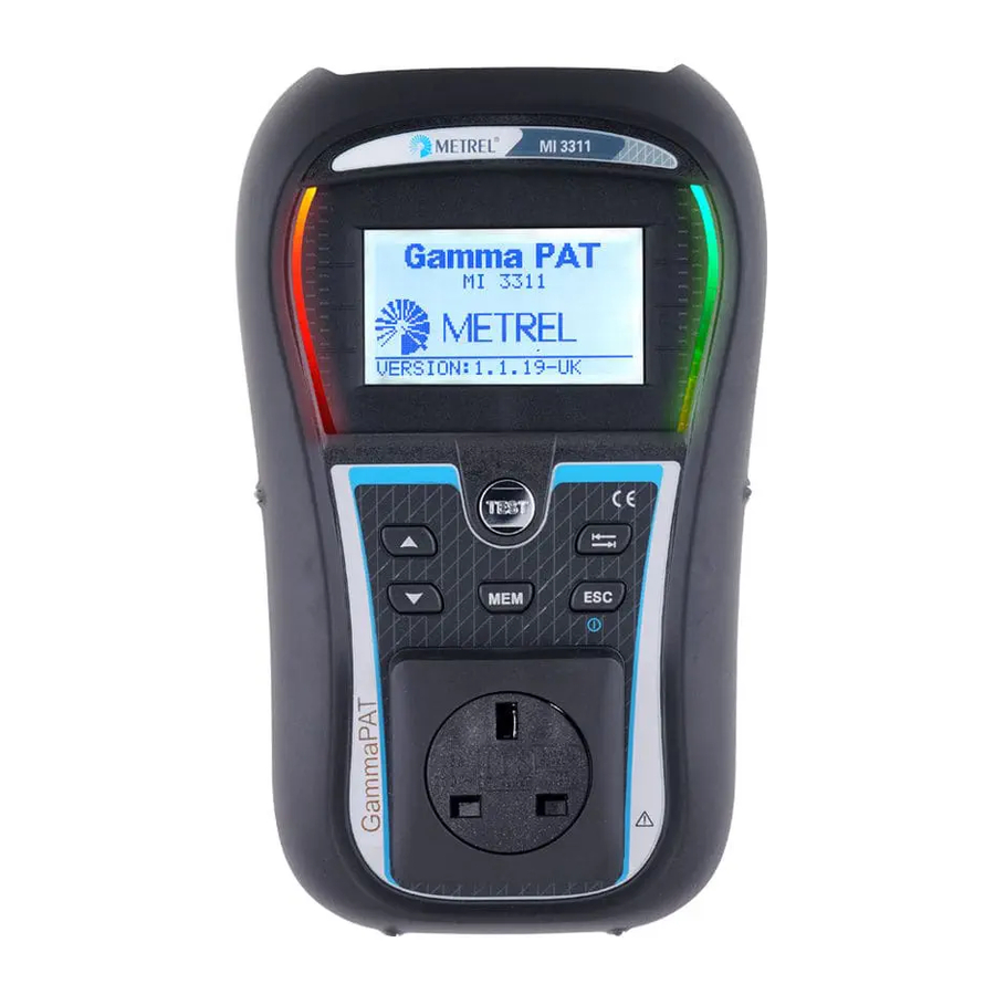
MI 3311 GammaPAT Instrument description 2 Instrument description 2.1 Front panel Figure 1.1: Front panel Legend: 128 x 64 dots matrix display with backlight. FAIL Red indicator Indicates PASS/ FAIL of result. PASS Green indicator TEST Starts testing / confirms selected option Selects parameter / changes value of selected parameter. -
Page 11: Connector Panel
MI 3311 GammaPAT Instrument description 2.2 Connector panel Figure 1.2: Connector panel Legend: 1 S/EB1 Probe and Earth continuity terminal 2 IEC IEC / Voltage input 3 Protection cover 4 Charger socket For connection of external charger 5 USB connector Communication with PC USB (1.1) port Communication with barcode reader Communication with printer... -
Page 12: Back Side
MI 3311 GammaPAT Instrument description 2.3 Back side Figure 1.3: Back side Legend: Inserts for side belt Battery compartment cover Fixing screw for battery compartment cover Back side information label Holder for inclined position of the instrument Figure 1.4: Battery compartment Legend: Battery cells Size AA, alkaline or rechargeable NiMH / NiCd... -
Page 13: Meaning Of Symbols And Messages On The Instrument Display
MI 3311 GammaPAT Instrument description 2.4 Meaning of symbols and messages on the instrument display Before performing a measurement, the instrument performs a series of pre-tests to ensure safety and to prevent any damage. These safety pre-tests are checking for any external voltage and load condition on test terminals. -
Page 14: Battery Indication
MI 3311 GammaPAT Instrument description WARNING! A high insulation test voltage will be present on the output of the instrument! WARNING! A high insulation test voltage is present on the output of the instrument. Measurement in progress. Test result can be saved. Connect the test lead to the S/EB1 test socket. -
Page 15: Technical Specifications
MI 3311 GammaPAT Technical specifications 3 Technical specifications 3.1 Earth continuity Range Resolution Accuracy 0.00 19.99 0.01 (5 % of reading + 3 digits) 20.0 199.9 0.1 Indication only 200 1999 1 ... -
Page 16: Substitute Leakage Current
MI 3311 GammaPAT Technical specifications 3.3 Substitute leakage current Range Resolution Accuracy 0.00 mA 9.99 mA 0.01 mA (5 % of reading + 3 digits) 10.0 mA 19.9 mA 0.1 mA Open circuit voltage ....<50 V AC at rated mains voltage Short circuit current.... -
Page 17: Checkbox Specification
MI 3311 GammaPAT Technical specifications 3.6 Checkbox specification Instrument Function Reference value Accuracy Earth continuity 0.50 +/- 1 % of value Earth continuity 2.00 +/- 1 % of value Substitute leakage current 5.90 mA +/- 1 % of value Substitute leakage current 0.50 mA +/- 1 % of value... - Page 18 MI 3311 GammaPAT Technical specifications Memory..........1500 memory locations The error in operating conditions could be at most the error for reference conditions (specified in the manual for each function) +1 % of measured value + 1 digit, unless otherwise specified in the manual for particular function. Communication transfer speed RS232 interface ........
-
Page 19: Main Menu And Test Modes
MI 3311 GammaPAT Main menu and test modes 4 Main menu and test modes 4.1 Instrument Main menu From the main menu of the instrument there are three operation modes, Help and Setup that can be selected. Figure 1.5: Instrument Main menu Keys: ... -
Page 20: Shortcut Menu
MI 3311 GammaPAT Main menu and test modes 4.3 Shortcut menu In this menu are all the most popular pre-defined autotest sequences that can be selected and performed (shown in Appendix C). When an autotest sequence has been completed, the measurement results can be stored into instrument internal memory. Figure 1.7: Autotest shortcut menu example See chapter 6.3 Carrying out (Simple, Shortcut) test sequences. -
Page 21: Setup Menu
MI 3311 GammaPAT Main menu and test modes 4.6 Setup menu In the Setup menu different parameters and settings of the instrument can be viewed or set. Figure 1.10: Setup menu Keys: / Select the setting to adjust or view: <MEMORY>... -
Page 22: Lcd Contrast And Backlight
MI 3311 GammaPAT Main menu and test modes Returns to Setup menu without changes. 4.9 LCD contrast and backlight In this menu the contrast and backlight mode of the LCD can be set. Figure 1.13: LCD menu Backlight modes: AUTO The high backlight level is active for 30 seconds after last pressing of any key. - Page 23 MI 3311 GammaPAT Main menu and test modes The Checkbox starting screen is displayed first. In the REF column the Checkbox reference values are displayed. Figure 1.14: Checkbox starting screen Keys: Starts instrument calibration procedure. TEST / Switches between Checkbox screens. Returns to Setup menu without changes.
-
Page 24: Nominal Voltage Selection
MI 3311 GammaPAT Main menu and test modes Checking the IEC test cord The connection for checking the IEC test cord is displayed. Before conducting the check, connect the IEC test cord. Figure 1.17: IEC test cord check starting screen Keys: TEST Starts IEC test cord checking procedure. -
Page 25: Shortcut Setup
Shortcuts makes all shortcuts available from the Shortcut Menu. Figure 1.15: Original settings menu Options: BASIC A limited list of (most popular) test sequences is set. ADVANCED The complete list of test sequences (supported by METREL) is set. Keys: / Selects the list. TEST Confirms selection and returns to Setup menu. -
Page 26: Setting Date And Time
MI 3311 GammaPAT Main menu and test modes Note: When enabling the fast mode then Visual Inspection and Functional Test will automatically be set to PASS. 4.14 Setting date and time Date and time can be set in this menu. Figure 1.21: Date and time menu Keys: Selects the field to be changed. -
Page 27: Instrument Data
MI 3311 GammaPAT Main menu and test modes TEST Selects the next letter. Confirms name and returns to User data menu. Deletes last letter. Returns to User data menu without changes. Notes: The selected user name will be printed on the simple label (initials). ... -
Page 28: Single Test
MI 3311 GammaPAT Single test 5 Single test In a Single test mode individual tests can be performed. This is especially helpful for troubleshooting. 5.1 Performing measurements in single test mode Select appropriate Single test in Single test Main menu. Figure 1.22: Single test Main menu Keys: ... -
Page 29: Measurements And Inspections
MI 3311 GammaPAT Single test 5.2 Measurements and inspections 5.3 Visual inspection A thorough visual check must be carried out before each electrical safety test. The following items should be checked: Inspection of device under test for sign of damage. ... -
Page 30: Earth Continuity Resistance
MI 3311 GammaPAT Single test 5.4 Earth continuity resistance This test ensures that the connections between the protective conductor terminal in the mains plug of the device under test and earthed accessible conductive parts of the device under test are satisfactory and of sufficiently low resistance. This test has to be performed on Class I (earthed) appliances. -
Page 31: Insulation Resistance
MI 3311 GammaPAT Single test 5.5 Insulation resistance The insulation resistance test checks the resistance between live conductors and earthed (or isolated) accessible metal parts of a device under test. This test can disclose faults caused by pollution, moisture, deterioration of the insulation material etc. The instrument measures the insulation resistance between: ... -
Page 32: Insulation Resistance - P
MI 3311 GammaPAT Single test Notes: When S/EB1 probe is connected during the test then the current through it is also considered. Consider any warning on the display before starting the measurement! Do not touch or disconnect the device under test during the measurement or before it is fully discharged! The message »Udisch …«... -
Page 33: Substitute Leakage
MI 3311 GammaPAT Single test Figure 1.33: Example of insulation resistance - P measurement results Displayed results: Main result ..... Insulation resistance (LN – P) Notes: The currents flowing through the PE terminal of the mains test socket will NOT be considered. -
Page 34: Substitute Leakage - P
MI 3311 GammaPAT Single test Substitute leakage measurement procedure Select the SUB. LEAKAGE function. Set the test parameters. Connect device under test to the instrument (see figure 5.14). Press the TEST key for measurement. Store the result by pressing MEM key (optional). Figure 1.36: Example of substitute leakage current measurement results Displayed results: Main result ..... - Page 35 MI 3311 GammaPAT Single test Test circuits for substitute leakage - P measurement Figure 1.38: Measurement of Substitute leakage - P current Substitute leakage - P measurement procedure Select the SUB. LEAKAGE-P function. Set the test parameters. Connect device under test to the instrument (see figure 5.17).
-
Page 36: Polarity Test
MI 3311 GammaPAT Single test 5.9 Polarity test This test checks the polarity of supply cords. The following faults can be detected: L OPEN, N OPEN, PE OPEN, L-N CROSS and MULTIPLE FAULT. Figure 1.40: Polarity test menu Test circuit for polarity test Figure 1.41: Polarity test of IEC cord Polarity test procedure ... -
Page 37: Functional Test
MI 3311 GammaPAT Single test 5.10 Functional test In its simplest form a functional test is a check to ensure that the appliance is working properly. Note: This test should only be performed once the appliance has passed all other tests applicable to the device under test. -
Page 38: Voltage Trms
MI 3311 GammaPAT Single test 5.11 Voltage TRMS It is a simple function that continuously measures the voltage across the IEC cord connector. Test circuit for voltage measurement Figure 1.44: IEC cord voltage measurement Voltage TRMS procedure Select the VOLTAGE TRMS function. ... -
Page 39: Automatic Test Sequences
All limits and tests are in compliance with currently valid standards and regulations. In case of any changes, new firmware will be available at your distributor or from Metrel directly. The number of autotest shortcut sequences that are offered by the instrument can be set in the SHORTCUT SETUP menu. -
Page 40: Selecting The Autotest Shortcut Sequence
MI 3311 GammaPAT Autotest sequences - a Substitute leakage - P and Insulation resistance - P test if Touch leakage test is selected. The operator must decide by itself if the alternative tests are applicable. Refer to chapter 1.1 Warnings for more information. 6.3 Selecting the autotest shortcut sequence Select SHORTCUT MENU in Main menu. -
Page 41: Carrying Out (Simple, Shortcut) Test Sequences
MI 3311 GammaPAT Autotest sequences 6.4 Carrying out (Simple, Shortcut) test sequences General meaning of keys during a Simple or Shortcut test sequence: TAB, / Sets option. Sets limit value in selected (highlighted) item. Cancels test sequence and returns to the top of the test menu without changes. -
Page 42: Insulation Resistance Measurement
MI 3311 GammaPAT Autotest sequences Options in Earth continuity result screen: NEXT Proceeds to next step. REPEAT Repeat the test (use in case of multiple earthed points). Highest result will be stored. 6.7 Insulation resistance measurement The test is offered if it is applicable according to the autotest setting. The Insulation starting screen is displayed first. -
Page 43: Insulation Resistance - P Measurement
MI 3311 GammaPAT Autotest sequences 6.9 Insulation resistance - P measurement The test is offered if it is applicable according to the autotest setting. The Insulation resistance - P starting screen is displayed first. Measurement and options in Insulation resistance - P starting screen are described in chapter 5.2.4 Insulation resistance - P. Figure 1.56: Insulation resistance - P starting screen After the measurement is carried out the Insulation resistance - P result screen is displayed. -
Page 44: Polarity Test
MI 3311 GammaPAT Autotest sequences 6.11 Polarity test The test is offered if it is applicable according to the autotest setting. The Polarity test starting screen is displayed first. Measurement and options in Polarity test starting screen are described in chapter 5.2.7 Polarity test. Figure 1.60: Polarity test starting screen After the measurement is carried out the Polarity test result screen is displayed. -
Page 45: Handling Autotest Results
MI 3311 GammaPAT Autotest sequences 6.13 Handling autotest results After the Simple / Shortcut autotest is finished, the Main autotest result screen will be displayed including an overall / indication. Figure 1.63: Main autotest result screen Options in Autotest results screen: Views individual results. -
Page 46: Working With Autotest Results
MI 3311 GammaPAT Working with autotest results 7 Working with autotest results 7.1 Saving autotest results After selecting Save results in Autotest results menu, the autotest results will be stored in the internal memory of the instrument. The appliance ID number and NAME can be added to the test results before the results are saved: Figure 1.66: Save results menu (Appliance ID) Keys:... -
Page 47: Recalling Results
MI 3311 GammaPAT Working with autotest results 7.2 Recalling results Saved autotest results can be recalled, printed or deleted from the Memory menu. Enter the Memory menu from the Setup menu. Figure 1.69: Memory menu To enter the Recall results menu select Recall results in Memory menu. A list of Appliance ID’s and NAMES are displayed in a chronological order (last performed measurement is displayed at the top of the list). -
Page 48: Deleting Individual Autotest Results
MI 3311 GammaPAT Working with autotest results 7.3 Deleting individual autotest results To enter the Delete results menu select Delete results in Memory menu. A list of Appliance ID’s and NAMES are displayed in a chronological order (last performed measurement will be displayed at the top of the list). In the lower window of the display the following data is displayed: ... -
Page 49: Printing And Rfid Tagging Of Individual Autotest Results
MI 3311 GammaPAT Working with autotest results 7.5 Printing and RFID tagging of individual autotest results To print labels or results and write RFID tags select Print data / RFID in Memory menu. A list of Appliance ID’s and NAMES are displayed in a chronological order (last performed measurement will be displayed at the top of the list). -
Page 50: Communication
MI 3311 GammaPAT Communication 8 Communication The instrument can communicate with the PATLink PRO PC software. The following actions are supported: Saved results can be downloaded and stored to a PC. Checkbox results can be downloaded and stored to the PC. ... -
Page 51: Measuring 110 V Appliances
MI 3311 GammaPAT Measuring 110V appliances 9 Measuring 110 V appliances The GammaPAT instrument allows measurements to be performed on 110 V appliances. When the 110 V adapter is used only the following measurements can be performed: Earth continuity resistance, ... -
Page 52: Maintenance
MI 3311 GammaPAT Maintenance Maintenance 10.1 Periodic calibration It is essential that all measuring instruments are regularly calibrated in order for the technical specification listed in this manual to be guaranteed. We recommend an annual calibration. The calibration should be done by an authorized technical person only. 10.2 Service For repairs under or out of warranty please contact your distributor for further information. -
Page 53: Instrument Set And Accessories
MI 3311 GammaPAT Instrument set and accessories Instrument set and accessories Standard set of the instrument Instrument GammaPAT Small soft carrying bag Soft hand strap Test lead with crocodile clip (1.5 m, black) IEC cord 2 m ... -
Page 54: Appendix A - Barcode Formats
MI 3311 GammaPAT Appendix A – Barcode formats Appendix A – Barcode formats The instrument GammaPAT supports two barcode formats (single and double). Autotest shortcut code and appliance ID Autotest shortcut codes are represented as a three digit code. These autotest codes can also be represented by the barcode. -
Page 55: Appendix B - Simple Test Codes (Uk)
MI 3311 GammaPAT Appendix B – Autotest shortcut codes (UK) Appendix B – Simple test codes (UK) Type Class Earth continuity Insulation S. Leakage Polarity Limit Limit Limit CLASS I 0.20 Ω 200 mA 1.00 MΩ 500 V 0.75 mA CLASS II 2.00 MΩ... -
Page 56: Appendix C - Autotest Shortcut Codes (Uk)
MI 3311 GammaPAT Appendix C – Autotest shortcut codes (UK) Appendix C – Autotest shortcut codes (UK) Autotests marked bold are available if SHORTCUT setup is set to BASIC. Refer to chapter 4.6.6 Shortcut Setup for more information. Type Class Fuse Cord Earth Bond Insulation S. - Page 57 MI 3311 GammaPAT Appendix C – Autotest shortcut codes (UK) Type Class Fuse Cord Earth Bond Insulation S. Leakage Leakage T. Leakage Code Limit Limit Limit Limit Limit Heating and Cooking short 0.10Ω 10 A - 0.75 mA short 0.10 Ω 10 A 1.00 mA 10 A short 0.10 Ω...
- Page 58 MI 3311 GammaPAT Appendix C – Autotest shortcut codes (UK) 2.00 MΩ 500 V 0.25 mA 2.00 MΩ 500 V IEC leads Surge protected = OFF / RCD protected = OFF Length Earth Bond Insulation Polarity Code Limit Limit 0.5mm / 3A ...
- Page 59 MI 3311 GammaPAT Appendix C – Autotest shortcut codes (UK) IEC leads Surge protected = ON RCD protected ? = OFF Length Earth Bond Insulation Polarity Code Limit Limit 0.5mm / 3A <=5 m 0.30 Ω 10 A 1.00 MΩ 250 V ...
- Page 60 MI 3311 GammaPAT Appendix C – Autotest shortcut codes (UK) Type Portable RCD Earth Bond Leakage Polarity Code Limit Limit 0.10 Ω 25 A 0.75 mA 30mA Auto active Type Class III equipment Visual Code Meaning of symbols used in autotest shortcut codes tables: test/measurement enabled, ...
Need help?
Do you have a question about the GammaPAT MI 3311 and is the answer not in the manual?
Questions and answers