Table of Contents
Advertisement
Advertisement
Table of Contents

Related Manuals for METREL EasiPLUS MI 3000


Summary of Contents for METREL EasiPLUS MI 3000
-
Page 1: Instruction Manual
EasiPLUS MI 3000 Instruction manual Version 1.0, HW 3; Code No. 20 752 201... - Page 2 Mark on your equipment certifies that this equipment meets the requirements of the EU (European Union) concerning safety and interference causing equipment regulations. No part of this publication may be reproduced or utilized in any form or by any means without permission in writing from METREL.
-
Page 3: Table Of Contents
MI 3000 EasiPLUS Table of contents Preface ......................5 Safety and operational considerations ............. 6 Warnings and notes ..................6 Batteries ..................... 9 Charging ..................... 9 Precautions on charging of new battery cells or cells unused for a longer period ...................... - Page 4 MI 3000 EasiPLUS Table of contents 5.4.1 Fault loop impedance ................39 5.4.2 The fault loop impedance test for RCD protected circuits ....41 Line impedance and prospective short-circuit current ......43 Phase sequence testing ................45 Voltage and frequency ................
-
Page 5: Preface
1 Preface Congratulations on your purchase of the EasiPLUS instrument and its accessories from METREL. The instrument was designed on a basis of rich experience, acquired through many years of dealing with electric installation test equipment. The EasiPLUS instrument is professional, multifunctional, hand-held test instrument intended to perform all the measurements required in order for a total inspection of electrical installations in buildings. -
Page 6: Safety And Operational Considerations
2.1 Warnings and notes In order to maintain the highest level of operator safety while carrying out various tests and measurements, Metrel recommends keeping your EasiPLUS instruments in good condition and undamaged.. When using the instrument, consider the following general warnings: symbol on the instrument means »Read the Instruction manual... - Page 7 MI 3000 EasiPLUS Safety and operational considerations Warnings related to measurement functions Insulation resistance Insulation resistance measurement should only be performed on de-energized objects! When measuring the insulation resistance between installation conductors, all loads must be disconnected and all switches closed! Do not touch the test object during the measurement or before it is fully ...
- Page 8 MI 3000 EasiPLUS Safety and operational considerations RCD functions Parameters set in one function are also kept for other RCD functions! The measurement of contact voltage does not normally trip an RCD. However, the trip limit of the RCD may be exceeded as a result of leakage current flowing to the PE protective conductor or a capacitive connection between L and PE conductors.
-
Page 9: Batteries
If the instrument is not to be used for a long period of time, remove all batteries from the battery compartment. Alkaline or rechargeable Ni-Cd or Ni-MH batteries (size AA) can be used. Metrel recommends only using rechargeable batteries with a capacity of 2100mAh or above. - Page 10 MI 3000 EasiPLUS Safety and operational considerations In this situation, Metrel recommend the following procedure to improve the battery lifetime: Completely charge the batteries for at least 14h via the instrument built-in charger. Completely discharge the batteries (this can be performed by using the ...
-
Page 11: Standards Applied
MI 3000 EasiPLUS Safety and operational considerations 2.5 Standards applied The EasiPLUS instrument is manufactured and tested in accordance with the following regulations: Electromagnetic compatibility (EMC) BS EN 61326 Electrical equipment for measurement, control and laboratory use – EMC requirements Class B (Hand-held equipment used in controlled EM environments) Safety (LVD) -
Page 12: Instrument Description
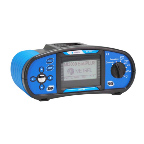
MI 3000 EasiPLUS Instrument description 3 Instrument description 3.1 Front panel Figure 3.1: Front panel Legend: 1..ON/OFF key, to switch the instrument on and off. The instrument will automatically switch off 10 minutes after the last key press / function switch rotation. - Page 13 MI 3000 EasiPLUS Instrument description Connector panel > 550V Figure 3.2: Connector panel Legend: 1..Test connector. Warning! Maximum allowed voltage between test terminals and ground is 600V! Maximal allowed voltage between test terminals is 550 V! 2..Power supply socket. 3..
-
Page 14: Back Panel
MI 3000 EasiPLUS Instrument description 3.2 Back panel Figure 3.3: Back panel Legend: 1..Battery/fuse compartment cover. 2..Information label. 3..Fixing screws for battery/fuse compartment cover. Fuse Fuse Fuse S/N XXXXXXXX SIZE AA SIZE AA SIZE AA Figure 3.4.: Battery and fuse compartment... -
Page 15: Bottom View
MI 3000 EasiPLUS Instrument description Legend: 1..Fuse F1. 2..Fuse F2. 3..Fuse F3. 4..Serial number label. 5..Battery cells (size AA). 6..Battery holder. 3.3 Bottom view Continuity (EN 61557-4) RCD (EN 61557-6) Low Contact voltage ... -
Page 16: Carrying The Instrument
MI 3000 EasiPLUS Instrument description 3.4 Carrying the instrument The neck strap supplied in standard set allows the instrument to be carried in a variety of different ways.. The operator can choose the most appropriate method based on the tasks they are performing. See the following examples: The instrument can be hung around operator's neck allowing the... -
Page 17: Instrument Operation
MI 3000 EasiPLUS Instrument operation 4 Instrument operation 4.1 Meaning of symbols and messages on the instrument display The instrument display is divided into four sections: Figure 4.1: Display outlook Legend: 1..Function and parameter line. In the top line of the display, the measuring function/sub-function and parameters are displayed. -
Page 18: Message Field - Battery Status
MI 3000 EasiPLUS Instrument operation 4.1.2 Message field – battery status Battery power indication. Low battery indication. Battery pack is too weak to guarantee correct result. Replace the batteries. Recharging is running (if power supply adapter is connected). 4.1.3 Message field – measurement warnings/messages Warning! High voltage is applied to the test terminals. -
Page 19: Result Field
MI 3000 EasiPLUS Instrument operation Fuse F1 (continuity circuit) blown or not inserted. S SF F Single fault condition in IT system. 4.1.4 Result field Measurement passed. Measurement failed. Measurement is aborted. Check the conditions at the input terminal. 4.1.5 Other messages Instrument settings and measurement parameters/limits are set to initial (factory) values. -
Page 20: Function And Parameter Line
MI 3000 EasiPLUS Instrument operation 4.1.7 Function and parameter line Figure 4.2: Function selector switch and belonging parameter line Legend: 1……Main function name. 2……Function or sub-function name. 3……Measuring parameters and limit values. 4.2 Selecting measurement function/ subfunction The following measurements can be selected with the function selector switch: Voltage and frequency, ... -
Page 21: Setup Menu
MI 3000 EasiPLUS Instrument operation Press the HELP key again to see further Help screens (if available) or to return to the function menu. Figure 4.3: Example of help menu 4.5 Setup menu In the Setup menu, the following actions can be taken: Supply system selection, ... -
Page 22: Impedance Scaling Factor Adjustment
MI 3000 EasiPLUS Instrument operation 4.5.2 Impedance scaling factor adjustment Select SET Z FACTOR in Setup menu by using and keys and press the TEST key to enter the Impedance scaling factor adjustment menu. Figure 4.6: Scaling factor adjustment menu Use the ... -
Page 23: Recalling Original Settings
MI 3000 EasiPLUS Instrument operation 4.5.5 Recalling original settings The following parameters and settings can be automatically set back to initial (factory) values: Test parameters and limit values, Contrast, Impedance scaling factor, Supply system, Support for remote commanders ... -
Page 24: Measurements
Resistance of semi-conductive (antistatic) floors. For additional information concerning insulation resistance measurements refer to Metrel’s handbook Measurements on electric installations in theory and practice. How to perform an insulation resistance measurement Select Insulation function with the function selector switch.The following... - Page 25 MI 3000 EasiPLUS Measurements Check the displayed warnings and online voltage/terminal monitor before Step 4 starting the measurement. If OK, press and hold the TEST key until the result has stabilised. Actual measured results are shown on the display during measurement.
-
Page 26: Continuity
MI 3000 EasiPLUS Measurements 5.2 Continuity Two continuity sub-functions are available: RLow, 200mA continuity test with automatic polarity reversal Low current (ca 7mA) continuous continuity test, useful when testing inductive systems (e.g. motors, see section 5.2.2 for more details). 5.2.1 R LowΩ... - Page 27 MI 3000 EasiPLUS Measurements 2. Press the TEST key in order to perform regular measurement. The displayed result should be close to 0.00 .(depending on the length of test leads used). 3. Press the CAL key. After performing test leads compensation the compensated test leads indicator Co will be displayed on the top line.
-
Page 28: Low Current Continuity Test
-meter with low-test current. The function can also be used to test inductive components such as motors and coiled cables. For additional information concerning continuity measurements refer to the Metrel’s handbook Measurements on electric installations in theory and practice. - Page 29 MI 3000 EasiPLUS Measurements Set the following limit value: Step 2 High limit resistance value. Connect test cable to the instrument and the item under test. Follow the Step 3 connection diagram shown in figures 5.10 and 5.11 to perform the Continuity measurement.
-
Page 30: Testing Rcds
MI 3000 EasiPLUS Measurements Notes: If a voltage of higher than 10 V exists between test terminals, the continuity measurement will not be performed. Before performing a continuity measurement, compensate for the test lead resistance (if necessary). The compensation is performed in Continuity sub- function R LowΩ. -
Page 31: Testing Selective (Time-Delayed) Rcds
N Uc 1.05 2 2 I N Table 5.1: Relationship between Uc and I For additional general information concerning contact voltage measurement refer to Metrel’s handbook Measurements on electric installations in theory and practice . - Page 32 MI 3000 EasiPLUS Measurements How to perform contact voltage measurement Select RCD function with the function selector switch first. Use the / keys to Step 1 select contact voltage function (Uc). The following menu will be displayed: Figure 5.14: Contact voltage measurement menu Set the following measuring parameters and limit values: Step 2 Nominal residual current,...
-
Page 33: Trip-Out Time
Test current of ½ I cannot cause trip-out of the RCDs. N For additional information concerning trip-out time measurement refer to the Metrel handbook Measurements on electric installations in theory and practice . How to perform trip-out time measurement Select the RCD function with the function selector switch and use the /... -
Page 34: Trip-Out Current
/ 2.2 I =10 mA) N N N N N for pulsating DC residual currents), until the RCD trips. For additional information concerning the trip-out current measurement, refer to Metrel’s handbook Measurements on electric installations in theory and practice . - Page 35 MI 3000 EasiPLUS Measurements How to perform trip-out current measurement Select RCD function with the function selector and use the / keys to select Step 1 the Trip-out current (RCD ) function. The following menu is displayed: Figure 5.19: Trip-out current measurement menu By using cursor keys the following parameters can be set in this Step 2 measurement:...
-
Page 36: Autotest
MI 3000 EasiPLUS Measurements 5.3.9 Autotest The purpose of the autotest function is to perform a complete RCD testing and measurement of most important associated parameters (contact voltage, fault loop resistance and trip-out time at different fault currents) with one press of a button. If a faulty parameter is noticed during the autotest, the test will stop to highlight the need for further investigation. - Page 37 MI 3000 EasiPLUS Measurements After re-activating the RCD, the autotest sequence automatically proceeds with step 2. 2. Trip-out time measurement with the following measurement parameters: Test current of I N Test current started with the negative half-wave at 180 ...
- Page 38 MI 3000 EasiPLUS Measurements 5. Trip-out time measurement with the following measurement parameters: Test current of ½ I N Test current started with the positive half-wave at 0 Measurement does not normally trip an RCD. The following menu is displayed: Figure 5.26: Step 5 RCD autotest results After performing step 5 the RCD autotest sequence automatically proceeds...
-
Page 39: Fault Loop Impedance And Prospective Fault Current
L-PE For additional information concerning fault loop impedance measurement refer to Metrel’s handbook Measurements on electric installations in theory and practice . 5.4.1.1 How to perform fault loop impedance measurement Select the LOOP function with the function selector switch and use the /... - Page 40 MI 3000 EasiPLUS Measurements The complete list of available fuse types can be found in Appendix A. Connect the test leads to the instrument and follow the connection diagram Step 3 shown in the figure 5.29 to perform fault loop impedance measurement. Figure 5.29: Connection of plug cable and universal test cable Check for any warnings displayed on the screen and check the online Step 3...
-
Page 41: The Fault Loop Impedance Test For Rcd Protected Circuits
L-PE For additional information concerning fault loop impedance measurement refer to Metrel’s handbook Measurements on electric installations in theory and practice . 5.4.2.1 How to perform RCD trip-lock measurement Select the LOOP function with the function selector switch and use the /... - Page 42 MI 3000 EasiPLUS Measurements Check for warnings on the display and check the online voltage/terminal Step 4 monitor before starting the measurement. If everything is ok, press the TEST key. After performing the measurement the results will appear on the display. Figure 5.32: Example of fault loop impedance measurement results using trip-lock function Displayed result:...
-
Page 43: Line Impedance And Prospective Short-Circuit Current
(264 V U 440 V) L-PE For additional information concerning line impedance refer to Metrel’s handbook Measurements on electric installations in theory and practice . How to perform line impedance measurement Select the LINE function with function selector switch. The following menu is... - Page 44 MI 3000 EasiPLUS Measurements Figure 5.34: Phase-neutral or phase-phase line impedance measurement Check for warnings displayed on the screen and check the online Step 4 voltage/terminal monitor before starting the measurement. If everything is ok, press the TEST key. After performing the measurement, the results will appear on the display together with the PASS/FAIL indication (if applicable).
-
Page 45: Phase Sequence Testing
This is why it is advisable to test phase rotation before connection is made. For information concerning phase sequence testing refer to Metrel’s handbook Measurements on electric installations in theory and practice . -
Page 46: Voltage And Frequency
MI 3000 EasiPLUS Measurements Figure 5.38: Example of phase sequence test result Displayed results: Ph ...Phase sequence, 1.2.3..Correct connection, 2.3.1..Invalid connection, -.-.- ..Irregular voltages. 5.7 Voltage and frequency Voltage measurements should be carried out regularly while dealing with electric installations (carrying out different measurements and tests, looking for fault locations, etc.). - Page 47 MI 3000 EasiPLUS Measurements Check the displayed warnings. The Voltage and Frequency test continually Step 3 runs, showing fluctuantions as they occur, these results are shown on the display during measurement. Figure 5.41: Examples of voltage and frequency measurements Displayed results: Ul-n..Voltage between phase and neutral conductors, Ul-pe..Voltage between phase and protective conductors, Un-pe ..Voltage between neutral and protective conductors.
-
Page 48: Testing The Pe Terminal
This test should be performed before a mains supply voltage is applied to the instrument circuitry and before installation is used. For additional information concerning PE terminal test, refer to Metrel’s handbook Measurements on electric installations in theory and practice . - Page 49 MI 3000 EasiPLUS Measurements Reversed phase and protection conductors! MOST DANGEROUS SITUATION! Figure 5.43: Connection of universal test cable to load connection terminals with reversed L and PE conductors Touch the PE test probe (TEST key) for a few seconds. If PE terminal is Step 3 connected to phase voltage a warning message will be displayed and instrument buzzer will sound.
-
Page 50: Maintenance
MI 3000 EasiPLUS Maintenance 6 Maintenance 6.1 Replacing fuses There are three fuses under back battery cover of the EasiPLUS instrument. M 0.315 A / 250 V, 20 5 mm This fuse protects internal circuitry of low-value resistance function if test probes are connected to the mains supply voltage by mistake. -
Page 51: Technical Specifications
MI 3100 EurotestEASI Fuse base tables 7 Technical specifications 7.1 Insulation resistance Insulation resistance (nominal voltages 100 V and 250 V Measuring range according to EN61557-2 is 0.017 M 199.9 M . Measuring range (M ) Resolution (M ... -
Page 52: Low Current Continuity
MI 3000 EasiPLUS Maintenance 9 V Open-circuit voltage......6.5 V Measuring current......min. 200 mA into load resistance of 2 Test lead compensation....up to 5 The number of possible tests with a new set of batteries ....up to 5500 Automatic polarity reversal of the test voltage. -
Page 53: Contact Voltage
MI 3000 EasiPLUS Maintenance 7.3.2 Contact voltage Measuring range according to EN61557-6 is 3.0 V 49.0 V for limit contact voltage 25 Measuring range according to EN61557-6 is 3.0 V 99.0 V for limit contact voltage 50 Measuring range (V) Resolution (V) Accuracy 0.0 ... -
Page 54: Fault Loop Impedance And Prospective Fault Current
MI 3000 EasiPLUS Maintenance 30 mA) Trip-out current (I N Measurement range corresponds to EN61557-6 requirements. Specified accuracies are valid for complete operating range. Accuracy Measuring range I Resolution I 0.2 I 1.1 I 0.05 ... -
Page 55: Line Impedance And Prospective Short-Circuit Current
MI 3000 EasiPLUS Maintenance Prospective fault current (calculated value) Measuring range (A) Resolution (A) Accuracy 0.00 19.99 0.01 20.0 99.9 Consider accuracy of fault 100 999 loop resistance measurement 1.00k 9.99k 10.0 24.4k No trip out of RCD. 7.5 Line impedance and prospective short-circuit current Line impedance Measuring range according to EN61557-3 is 0.25 ... -
Page 56: Online Voltage Monitor
MI 3000 EasiPLUS Maintenance 7.8 Online voltage monitor Measuring range (V) Resolution (V) Accuracy 0 500 (2 % of reading + 2 digits) Nominal frequency range....0 Hz, 45 Hz 65 Hz If voltage greater than 500 V is applied to the test terminals, online voltage monitor is used as voltage indicator only. -
Page 57: A Fuse Base Tables
MI 3000 EasiPLUS Maintenance Fuse base tables Fuse type B Fuse type C Rated Disconnection time [s] Rated Disconnection time [s] current current Max. loop impedance () Max. loop impedance () 12,264 12,264 6,136 6,136 3,064 3,064 3,68 3,68 1,84 1,84 2,296 2,296... -
Page 58: Bit Supply Systems
IT supply systems IT supply systems In order for the operator to be familiar with the measurements and their typical applications on IT supply systems, it is advisable to read Metrel’s handbook Measurements on IT power supply systems . Standard references... - Page 59 MI 3000 EasiPLUS IT supply systems either at the neutral point or at midpoint of the system or at an artificial neutral point. The latter may be connected directly to earth if the resulting impedance to earth is sufficiently high at the system frequency. Where no neutral point or mid-point exists a line conductor may be connected to earth through high impedance.
- Page 60 MI 3000 EasiPLUS IT supply systems Measurement guides The user has to select the IT supply system in the instrument before testing it. The procedure for selecting the IT supply system is defined in chapter 4.4.1 Supply system setup . Once the IT system is selected the instrument can be used immediately. The instrument keeps selected IT system when it is turned off.
- Page 61 MI 3000 EasiPLUS IT supply systems B.3.2 Line impedance See chapter 5.5 Line impedance and prospective short-circuit current , the measurement is the same; only terminal voltage monitor indication corresponds to IT system. B.3.3 RCD testing RCD testing is performed in the same way as in TN/TT system (See chapter 5.3 Testing RCDs ), with the following exception: Contact voltage measurement is not relevant.
-
Page 62: C Reduced Low Voltage Supply Systems
Reduced low voltage supply systems Standard reference BS7671 Fundamentals Special supply systems are applied where inherent protection against electric shock is required but no SELV used. Reduced low voltage supply with ground reference can be used for this purpose. There are two options with 110 V nominal voltage. - Page 63 MI 3000 EasiPLUS IT supply systems Line resistance Line resistance Resistance R L1-L2 Prospective short circuit for U = 110 V. L1-L2 current Fault loop resistance Fault loop resistance Both fault loops, R (L1-PE) and R (L2-PE). Prospective fault current and I for both fault loops.
- Page 64 MI 3000 EasiPLUS IT supply systems C.3.3 Line resistance and prospective short circuit current Measured resistance represents Line-Line resistance (R ). Nominal system voltage L1-L2 for calculation of I is set to 110 V. Nominal system voltage range for line resistance measurement is 90 V to 121 V. If input voltage is out of range it is displayed on terminal voltage monitor, together with the indicator of disabled test C.3.4 Fault loop resistance and prospective fault current...
- Page 65 MI 3000 EasiPLUS IT supply systems Technical specifications Only those technical specifications are listed below that are different to specifications from chapter 7 of this document. C.4.1 RCD testing C.4.2 General data Nominal residual current....10 mA, 30 mA, 100 mA, 300 mA, 500 mA, 1000 mA Nominal residual current accuracy..
- Page 66 MI 3000 EasiPLUS IT supply systems Trip-out time Complete measurement range corresponds to EN61557-6 requirements. Specified accuracies are valid for complete operating range. General (non-delayed) RCDs Measuring range (ms) Resolution (ms) Accuracy 0 300 (½ I N N ...
- Page 67 MI 3000 EasiPLUS IT supply systems C.4.4 Fault loop resistance and prospective fault current Rs sub-function Measuring range according to EN61557-3 is 0.32 1999 . Measuring range ( ) Resolution ( ) Accuracy 0.00 19.99 0.01 20.0 ...
- Page 68 MI 3000 EasiPLUS IT supply systems C.4.5 Line resistance and prospective short-circuit current Line resistance Measuring range according to EN61557-3 is 0.25 1999 . Measuring range ( ) Resolution ( ) Accuracy 0.00 19.99 0.01 20.0 ...
Need help?
Do you have a question about the EasiPLUS MI 3000 and is the answer not in the manual?
Questions and answers