Table of Contents
Advertisement
Advertisement
Table of Contents

Related Manuals for METREL MI 3200


Summary of Contents for METREL MI 3200
- Page 1 TeraOhm 10 kV MI 3200 User Manual Version 4.0; Code No. 20 751 097...
- Page 2 Mark on your equipment certifies that this equipment meets the requirements of the EU (European Union) concerning safety and interference causing equipment regulations © 2015 Metrel No part of this publication may be reproduced or utilized in any form or by any means without permission in writing from METREL.
-
Page 3: Table Of Contents
MI 3200 TeraOhm 10 kV Table of contents Table of contents 1. General introduction ....................4 1.1. Features ........................ 4 1.2. Applied Standards ....................4 2. Instrument Description ..................... 5 2.1. Instrument Casing ....................5 2.2. Operator’s Panel ....................5 2.3. -
Page 4: General Introduction
MI 3200 TeraOhm 10 kV General introduction 1. General introduction 1.1. Features The TeraOhm 10 kV Tester is a portable battery / mains powered test instrument intended for the testing of Insulation Resistance by using high test voltages of up to 10kV. -
Page 5: Instrument Description
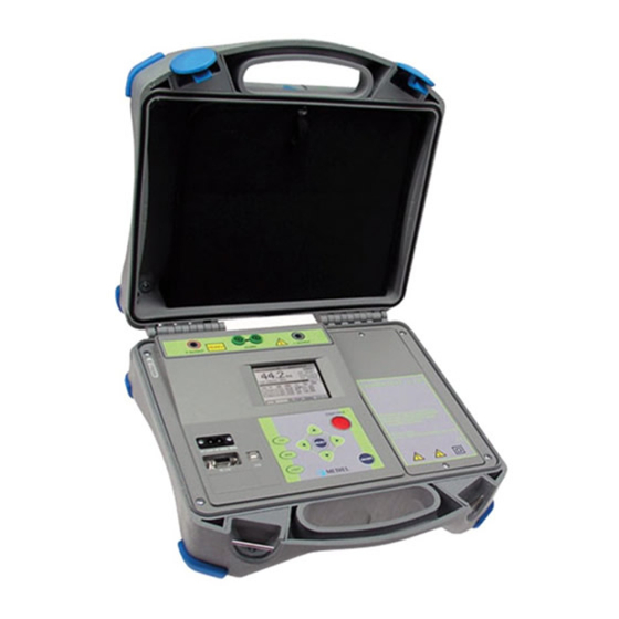
MI 3200 TeraOhm 10 kV Instrument Description 2. Instrument Description 2.1. Instrument Casing The instrument is housed in a plastic box that maintains the protection class defined in the general specifications. 2.2. Operator’s Panel The operator’s panel is shown in the figure below (Fig.1). -
Page 6: Accessories
The accessories consist of standard and optional accessories. Optional accessories can be delivered upon request. See attached list for standard configuration and options or contact your distributor or see the METREL home page: http://www.metrel.si. 2.4. Test leads The standard length of test leads is 2m, optional lengths are 8m and 15m. For more details see attached list for standard configuration and options or contact your distributor or see the METREL home page: http://www.metrel.si. -
Page 7: High Voltage Shielded Test Lead With High Voltage Tip
MI 3200 TeraOhm 10 kV Instrument Description 2.4.1. High voltage shielded test lead with High voltage tip Application notes: This test lead is designed for hand held testing of insulation. Insulation ratings: High voltage tip (red): 10kV d.c (double insulation);... -
Page 8: Warnings And Notes
3. Warnings and notes In order to maintain the highest level of operator safety while carrying out various tests and measurements Metrel recommends keeping your TeraOhm 10 kV test equipment in good condition and undamaged. When using this test equipment, consider the following general warnings: ... - Page 9 Note: For manual discharge Metrel recommends the use of A 1513 Discharge link. The internal discharge resistors of A 1513 ensure a damped discharge up to 10 uF at 10 kV.
-
Page 10: Performing Measurements
MI 3200 TeraOhm 10 kV Performing measurements 4. Performing measurements 4. 1. Switching on the instrument Autocalibration The instrument is switched ON by pressing the ON/OFF key. After turning on, the instrument will execute the autocalibration (Fig. 3). Note: If batteries are defective or missing and the instrument is powered from mains supply, the instrument will not turn ON Measuring test leads should be disconnected during autocalibration. -
Page 11: Configuration
MI 3200 TeraOhm 10 kV Performing measurements Mains powered instrument operation If you connect instrument to the mains supply when instrument is turned OFF, internal charger will begin to charge the batteries but instrument will remain turned OFF. In button left angle of LCD, flashing battery indicator will appear to indicate that the batteries are charging. -
Page 12: Setup
MI 3200 TeraOhm 10 kV Performing measurements 1. Highlight the Memory Clear option using and arrows. 2. Press the SELECT key, (“Press MEM to confirm!” message will be displayed). 3. Press the MEM key to clear all memory locations or ESC to cancel the activity. - Page 13 MI 3200 TeraOhm 10 kV Performing measurements Parameter Value Note Contrast 0%..100% Adjustment of the LCD contrast Time Set real time (hour: minute) Date Set current date (day-month-year) Com Port RS 232 2400, Set communication mode and rate. RS 232 4800,...
-
Page 14: Measurements
MI 3200 TeraOhm 10 kV Measurements 5. Measurements 5.1. Generally Information about High DC voltage testing The purpose of insulation tests Insulating materials are important parts of almost every electrical product. The material’s properties depend not only on its compound characteristics but also on temperature, pollution, moisture, ageing, electrical and mechanical stress, etc. - Page 15 MI 3200 TeraOhm 10 kV Measurements and R - the surface resistivity (position of optional guard connection) iss1 iss2 – the actual insulation resistance of material – capacitance of material - represents polarization effects. The Fig. 7 shows typical currents for that circuit.
- Page 16 In general, insulators that are in good condition will show a “high” polarization index while insulators that are damaged will not. Note that this rule is not always valid. Refer to Metrel’s handbook Insulation Testing Techniques for more information. General applicable values:...
-
Page 17: Guard Terminal
MI 3200 TeraOhm 10 kV Measurements Withstanding voltage test Some standards allow the use of a DC voltage as an alternative to AC withstanding voltage testing. For this purpose the test voltage has to be present across the insulation under test for a specific time. The insulation material only passes if there is no breakdown or flash over. -
Page 18: Filter Options
MI 3200 TeraOhm 10 kV Measurements +OUT +OUT -OUT GUARD -OUT Fig. 8. Connection of GUARD terminal to measured object where: Ut ..Test voltage ..Leakage current (resulted by surface dirt and moisture) ..Material current (resulted by material conditions) .. -
Page 19: Voltage Measurement
MI 3200 TeraOhm 10 kV Measurements THE PURPOSE OF FILTERING In simple terms the filters smooth the measured currents by means of averaging and bandwidth reduction. There are various sources of disturbance: AC currents at the mains frequency and its harmonics, switching transients etc, cause the results to become unstable. -
Page 20: Insulation Resistance Measurement
MI 3200 TeraOhm 10 kV Measurements Press the START key to start the measurement, continuous measurement starts to run. Press the START key again to stop the measurement. The result (see the right figure in the Fig. 9) can optionally be saved by pressing the MEM key twice, see chapter 6.1 Store, Recall and Clear Operation. - Page 21 MI 3200 TeraOhm 10 kV Measurements Initial display - graphical mode Display with results - graphical mode Fig. 11. Insulation Resistance function display states - Graph R(t) enabled Measurement procedure: Connect the test leads to the instrument and to the test object.
- Page 22 MI 3200 TeraOhm 10 kV Measurements Setting up parameters for Insulation Resistance: Press the SELECT key, the set-up menu will appear on the display, see the Fig.12. Select the parameter (line) to be set using the and keys;...
- Page 23 MI 3200 TeraOhm 10 kV Measurements Fig. 14 . Set-up menu of the Graph R(t) Notes: If the Timer is OFF is not possible to Enable the Graph R(t). The time duration of Graph R(t) is equal to the value of Timer.
-
Page 24: Diagnostic Test
MI 3200 TeraOhm 10 kV Measurements 5.6. Diagnostic test Selecting this function displays the following states (initial state and state with results after the completion of the measurement). The Fig. 15 shows states when Graph R(t) is disabled. Initial display – numerical mode Display with results –... - Page 25 MI 3200 TeraOhm 10 kV Measurements Diagnostic test is a long duration test for evaluating the quality of the insulation material under test. The results of this test enable the decision to be made on the preventive replacement of the insulation material. DIELECTRIC ABSORPTION RATIO (DAR) DAR is ratio of Insulation Resistance values measured after 15s and after 1 minute.
- Page 26 MI 3200 TeraOhm 10 kV Measurements PI Note: When determining Riso (1min) pay close attention to the capacitance of the object under test. It has to be charged-up in the first time section (1 min). Approximate maximum capacitance using: ...
- Page 27 MI 3200 TeraOhm 10 kV Measurements The result can optionally be saved by pressing the MEM key twice, see the chapter 6.1. Store, Recall and Clear Operation. Legend of displayed symbols: DIAGNOSTIC TEST Name of selected function Fil0 (Fil1, Fil2, Fil3)
- Page 28 MI 3200 TeraOhm 10 kV Measurements Legend of displayed symbols: DIAGNOSTIC TEST Name of selected function SETTING PARAMETERS: Unominal 5000V Set test voltage – step 25 V Time1 01min Time node to take R1min result Time node to take R2min result and...
- Page 29 MI 3200 TeraOhm 10 kV Measurements Fig. 20. Set-up menu of the Graph R(t) Notes: The time duration of Graph R(t) is equal to the value of Timer 3. The Timer value could be very long (up to 100 minutes), so the Special automatic decimation algorithm is use to write the Graph R(t) to the LCD.
-
Page 30: Step Voltage Insulation Resistance Testing
MI 3200 TeraOhm 10 kV Measurements 5.7. Step Voltage Insulation Resistance testing Selecting this function displays the following states (initial state and state with results after the completion of the measurement). The Fig. 21 shows states when Graph R(t) is disabled. - Page 31 MI 3200 TeraOhm 10 kV Measurements In this test, the insulation is measured in five equal time periods with test voltages from one fifth of the final test voltage up to full voltage (see the Fig. 23). This function illustrates the relationship of a materials Insulation resistance and its applied voltage.
- Page 32 MI 3200 TeraOhm 10 kV Measurements U1=1077V step voltage step voltage U2=2142V step voltage U3=3239V U4=4283V step voltage U5=5308V step voltage Notes: Timer information is displayed from the start of the measurement until the completion of each step measurement. Timer information shows the complete measurement period after the completion of the measurement.
-
Page 33: Withstanding Voltage
MI 3200 TeraOhm 10 kV Measurements Fig. 26. Set-up menu of the Graph R(t) Notes: The time duration of Graph R(t) is equal to the value of Step Time Multiplied by 5. The Timer value could be very long (up to 150 minutes), so the Special automatic decimation algorithm is use to write the Graph R(t) to the LCD. - Page 34 MI 3200 TeraOhm 10 kV Measurements Ustep ... Voltage step approx. 25 V (fixed value - not presetable) Ustart .. Starting voltage Tstep ... Test voltage duration per step Tend ..Constant test voltage duration after reaching End value t ... Time Ub ..
- Page 35 MI 3200 TeraOhm 10 kV Measurements Legend of displayed symbols: WITHSTANDING VOLTAGE DC Name of selected function SETTING PARAMETERS: Ustart 2000V Start test voltage, step = 25 V Ustop 7000V Stop test voltage, step = 25 V Tstep 00min 00s...
-
Page 36: Working With Your Results
MI 3200 TeraOhm 10 kV Operation with Results 6. Working with your Results 6.1. Storing, Recalling and Clearing Results The instrument contains battery supported storage memory to retain results when power is disconnected. This enables the test engineer to make the measurements and then to recall them later on. - Page 37 MI 3200 TeraOhm 10 kV Operation with Results Function List of stored data Function name Voltage Measured voltage Frequency the measured voltage Ser. number of stored result Date * Time * Function name Insulation resistance Measured insulation resistance value Set test voltage...
-
Page 38: Transferring Data To A Pc
MI 3200 TeraOhm 10 kV Operation with Results Step voltage Function name Last measured insulation resistance Set test voltage Actual test voltage - measured value Actual test current - measured value Capacitance of the tested object Complete duration of the measurement... -
Page 39: Maintenance
MI 3200 TeraOhm 10 kV Maintenance 7. Maintenance 7.1. Inspection To maintain the operator’s safety and to ensure the reliability of the instrument it is advisable to inspect the instrument on a regular basis. Check that the instrument and its accessories are not damaged. - Page 40 MI 3200 TeraOhm 10 kV Maintenance Battery cells are stored in the bottom section of the instrument casing under the battery cover (see Fig. 31). In case the batteries become defective please note the following: Turn the power off and disconnect any measurement accessories or mains supply cable connected to the instrument before opening the battery cover to avoid electric shock.
-
Page 41: Cleaning
MI 3200 TeraOhm 10 kV Maintenance 7.3. Cleaning Use a soft cloth, slightly moistened with soapy water or spirit to clean the surface of the instrument and leave the instrument to dry totally before using it. Notes! Do not use liquids based on petrol or hydrocarbons! ... -
Page 42: Specifications
MI 3200 TeraOhm 10 kV Specifications 8. Specifications 8.1. Measurement specifications Note: All data regarding accuracy is given for nominal (reference) environment condition. Insulation resistance Nominal test voltage: Any within 500 and 10000 V Current capability of test generator: >1 mA 5 mA ... - Page 43 MI 3200 TeraOhm 10 kV Specifications Noise current rejection (resistive load) Filter option Maximum current @ 50Hz (mA r.m.s). Fil0 Fil1 Fil2 Fil3 Generator Capability vs Resistance [ M ] Utest=10kV Utest=5kV Dielectric absorption ratio DAR Display range DAR Resolution Accuracy 0.01 ...
- Page 44 MI 3200 TeraOhm 10 kV Specifications Display range Test voltage (V) Resolution Accuracy 0 9999 V (3 % of reading + 3 V) 10 kV (3 % of reading) 0.1 kV Withstanding voltage DC DC test voltage: Voltage value: Any value within 500V and 10kV.
-
Page 45: General Specifications
MI 3200 TeraOhm 10 kV Specifications 8.2. General specifications Battery power supply ........7.2 V DC (6 × 1.2V NiMH D size) Mains power supply ........90-260 V AC, 45-65 Hz, 70 VA ............... (300V CAT III) Protection classification ........double insulation Over-voltage category ........ - Page 46 MI 3200 TeraOhm 10 kV Specifications CLOCK Built-in Real time clock ........Displayed permanently and stored as a parameter in combination with the result.
Need help?
Do you have a question about the MI 3200 and is the answer not in the manual?
Questions and answers