
Related Manuals for METREL SigmaGT MI 3310


Summary of Contents for METREL SigmaGT MI 3310
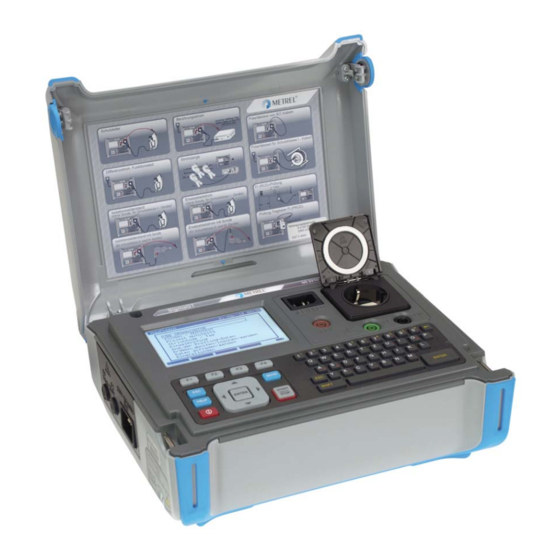
- Page 1 SigmaGT MI 3310 / MI 3310A Instruction Manual Version: 2.2, HW 2, Code no. 20 751 946...
- Page 2 Mark on your equipment certifies that this equipment meets the requirements of the EU (European Union) regulations concerning safety and electromagnetic compatibility No part of this publication may be reproduced or utilized in any form or by any means without permission in writing from METREL.
-
Page 3: Table Of Contents
MI 3310 / MI 3310A SigmaGT Table of contents General description .................... 7 Warnings ......................8 Warning markings on connector panel .............. 8 Standards applied ..................... 8 Battery and charging ..................10 ... - Page 4 MI 3310 / MI 3310A SigmaGT Table of contents 4.2.8.7 Reset instrument settings ................38 4.2.8.8 Communication settings .................. 39 4.2.8.9 Password ......................41 4.2.8.10 Calibration unit – checkbox (optional) ............42 Single tests ......................45 Performing measurements in single test mode ..........45 ...
- Page 5 MI 3310 / MI 3310A SigmaGT Table of contents 6.4.2 Reading autotest code from barcode / QR code ........92 6.4.3 Reading barcode for working with results ..........92 Performing autotest sequences – for appliances ..........93 ...
- Page 6 MI 3310 / MI 3310A SigmaGT Table of contents C.1 List of country modifications ................129 F.2 Modification issues - NL ..................129 F.2.1 Autotest organizer ..................129 F.2.2 Example of creating a test sequence with autotest organizer ....130 ...
-
Page 7: General Description
Soft touch keyboard with cursor keys, Built in real time clock, Built in calibration unit – checkbox (optional), Fully compatible with new METREL PATLink PRO PC software package. Powerful functions for fast and efficient periodic testing are included: Pre-programmed test sequences,... -
Page 8: Warnings
MI 3310 / MI 3310A SigmaGT General description Warnings In order to reach high level of operator safety while carrying out various measurements using SigmaGT instrument, as well as to keep the test equipment undamaged, it is necessary to consider the following general warnings: Read this user manual carefully, otherwise use of the instrument may be ... - Page 9 MI 3310 / MI 3310A SigmaGT General description Electromagnetic compatibility (EMC) EN 61326-1 Electrical equipment for measurement, control and laboratory use - EMC requirements -- Part 1: General requirements Class B (Portable equipment used in controlled EM environments) Safety (LVD) EN 61010-1 Safety requirements for electrical equipment for measurement, control, and laboratory use –...
-
Page 10: Battery And Charging
If the instrument is not to be used for a long period of time, remove all batteries from the battery compartment. Alkaline or rechargeable Ni-Cd or Ni-MH batteries (size C) can be used. Metrel recommends only using rechargeable batteries with a capacity of 4000 mAh or higher. - Page 11 MI 3310 / MI 3310A SigmaGT General description Repeat the charge / discharge cycle Four cycles are recommended in order to at least 2-4 times. restore the batteries to their normal capacity. Notes: The charger in the instrument is a pack cell charger. This means that the battery ...
-
Page 12: Instrument Description
MI 3310 / MI 3310A SigmaGT Instrument description 2 Instrument description Front panel Front panel Legend: 1 240 128 dots graphic matrix display with backlight 2 Function keys intended for displayed defined options. 3 ESCAPE key 4 HELP key 5 ON / OFF key To switch off the instrument press and hold ON/OFF key for about 2 seconds. -
Page 13: Connector Panels
MI 3310 / MI 3310A SigmaGT Instrument description Warning! These sockets are intended only for the connection to de-energized devices. 12 Test socket Warning! Dangerous voltage is present on the test socket during the measurement. Maximum output current is 16 A, test only devices with maximum rated supply current no higher than 16 A! Note: For devices incorporated high reactive loading, e.g. -
Page 14: Safety Pre-Tests
MI 3310 / MI 3310A SigmaGT Instrument description Right side connector panel 18 Current clamp adapter input sockets Warnings! Do not connect any voltage source on this input. It is intended only for connection of current clamp with current output. Maximum input current is 30 mA! Green socket is connected to the functional earth of the system and is ... -
Page 15: Warnings, Messages And Symbols
MI 3310 / MI 3310A SigmaGT Instrument description 2.4 Warnings, messages and symbols Warnings and messages Warning for improper supply voltage condition. Possible causes: Mains voltage is not No earth connection or other wiring problem on correct or PE not supply socket. - Page 16 MI 3310 / MI 3310A SigmaGT Instrument description Dangerous leakage current (higher than 3.5 mA) will flow if Leakage LN-PE high! power would be connected to DUT. Select YES or NO with Y or N key. Are you sure to Proceed with testing only if all safety measures have been proceed (Y/N)? taken.
- Page 17 MI 3310 / MI 3310A SigmaGT Instrument description Warning! More than 80 % of Instrument memory is almost full. Download stored results to memory is occupied. Stored data should be downloaded to PC. Warning! Recalibration of the instrument is required. Contact your Calibration has been dealer.
- Page 18 MI 3310 / MI 3310A SigmaGT Instrument description Warning symbols Remove the EB/S connection, especially if it is connected to any part that will begin to rotate or move when power is applied. Connect the test lead to the EB/S test socket. Warning! A high voltage is / will be present on the instrument output! (Insulation test voltage, or mains voltage).
- Page 19 MI 3310 / MI 3310A SigmaGT Instrument description Battery and mains supply indication Battery capacity indication. Low battery! Battery is too weak to guarantee correct result. Replace or recharge battery cells. Instrument connected to the mains supply voltage. When instrument is in idle mode recharging process is in progress. Recharging in progress (if instrument is connected to the mains supply voltage).
-
Page 20: Technical Specifications
MI 3310 / MI 3310A SigmaGT Technical specifications 3 Technical specifications Earth bond resistance Test current set to 10 A (MI 3310A only) Range Resolution Accuracy 0.00 1.99 0.01 (5 % of reading + 3 digits) 2.00 ... -
Page 21: Subleakage Current, Subleakage - S Current
MI 3310 / MI 3310A SigmaGT Technical specifications Power by: ......battery or mains Nominal voltages: .... 250 V DC, 500 V DC (- 0 %, + 10 %) Measuring current: ... min. 1 mA at 250 k (250 V), 500 k (500 V) Short circuit current: .. -
Page 22: Touch Leakage Current
MI 3310 / MI 3310A SigmaGT Technical specifications Powered by: ..... mains Test duration [s]: ....2 s, 3 s, 5 s, 10 s, 30 s, 60 s, 120 s, 180 s, none Test terminals: ....mains test socket Touch leakage current Range Resolution Accuracy... -
Page 23: Prcd And Rcd Testing
MI 3310 / MI 3310A SigmaGT Technical specifications Temperature coefficient outside reference temperature limits is 1 % of measured value per C. PRCD and RCD testing 3.9.1 Portable RCD trip-out time/current AC and A type PRCD trip-out time: Range Resolution Accuracy 0 ms ... -
Page 24: Calibration Unit - Checkbox (Optional)
MI 3310 / MI 3310A SigmaGT Technical specifications Powered by: ..... mains via tested RCD Test current type: ..... AC (sine-wave), A (pulsed), B (smooth DC) Test current: ....½I , 5I N N N Start angle: ...... 0 (+), 180 (-), both (+,-) Test modes: ..... - Page 25 MI 3310 / MI 3310A SigmaGT Technical specifications Protection classification Power supply: ......Class I, mains supply Class II, only battery supply Pollution degree: ....... 2 Degree of protection: ....IP 30 (closed and locked cover) IP 20 main test socket Case: ........
-
Page 26: Main Menu And Test Modes
For testing 3-phases appliances and/or welding machines the 3-phase operation mode must be enabled and the SigmaGT must be connected to a Metrel A1322 or A1422 3-phase Active GT / Machine adapter (Plus). Refer to 3-phase adapter for detailed information. -
Page 27: Instrument Main Menu
MI 3310 / MI 3310A SigmaGT Main menu and test modes Instrument main menu From the Main menu all the instrument functions can be selected. Instrument main menu Keys in instrument main menu: / Select one of the following menu items: <AUTOTEST ORGANIZER>, pre-defined autosequences, covering requirements of standard;... -
Page 28: Autotest Custom Menu
MI 3310 / MI 3310A SigmaGT Main menu and test modes Autotest organizer menu See chapter 6 Autotest sequences for detailed description of this test mode. 4.2.2 Autotest custom menu The menu contains a list of custom prepared autosequences. Two sets (one for portable appliances and one for welding machines) of pre- programmed often used autotest sequences are added to the list by default. -
Page 29: Project Autotests Menu
MI 3310 / MI 3310A SigmaGT Main menu and test modes 4.2.3 Project autotests menu The Project autotest is a tool that simplifies and speeds up periodic testing of DUTs. The main idea is to re-use known and stored data about the DUT. Project autotest starting menu example See chapter 6.3 Project autotests for detailed description about this autotest mode. -
Page 30: Edit Appliance Data Menu
MI 3310 / MI 3310A SigmaGT Main menu and test modes See chapter 5 Single tests for detailed description about the single test mode. Note: 3-Phase adapter A1422 combined with the SigmaGT instrument should be used for welding machine tests. 4.2.5 Edit appliance data menu In this menu lists of user and appliance data default names can be edited. -
Page 31: Item Editing Menu
MI 3310 / MI 3310A SigmaGT Main menu and test modes 4.2.5.1.1 Item editing menu The menu is intended for editing new/existing fields. Item editing menu – example edit users Keys in item editing menu: Alphanumeric keys Entering item name. SAVE (F1) Confirms entry and returns back. -
Page 32: Test Sites Submenu
MI 3310 / MI 3310A SigmaGT Main menu and test modes 4.2.5.3 Test sites submenu In this menu default lists of object names (up to 100) can be edited. The list can be also downloaded to/ uploaded from the PC SW PATlinkPRO. For more information refer to chapter 7.5 Data upload / download. -
Page 33: Recall / Delete / Send Memory Menu
MI 3310 / MI 3310A SigmaGT Main menu and test modes 4.2.6 Recall / delete / send memory menu Manipulation with stored data is allowed in this menu. Stored results can be recalled according to DUT name and date, deleted or send to PC or printers. Recall results menu See chapters 7.2 Recalling results, 7.3 Deleting results and 7.4 Downloading and printing results for more information. -
Page 34: Setting Date And Time
MI 3310 / MI 3310A SigmaGT Main menu and test modes Setup menu Keys in Setup menu: / Selects the setting to adjust or view: <DATE/TIME>, day and time, see 4.2.8.1; <LANGUAGE>, instrument language, see 4.2.8.2; <PRINT HEADER>, printed header options, see 4.2.8.3; <INSTRUMENT DATA>, data related to the SigmaGT, see 4.2.8.4;... -
Page 35: Language Selection
MI 3310 / MI 3310A SigmaGT Main menu and test modes Notes: Date is attached to each PAT autotest measurement results! Date format is DD-MM-YYYY (day–month–year). Date entry is checked for regularity and is not accepted in case of irregular date! ... -
Page 36: Viewing Of Instrument Data
MI 3310 / MI 3310A SigmaGT Main menu and test modes 4.2.8.4 Viewing of instrument data In this menu the following instrument data are shown: Producer name, Instrument name, Calibration date, Serial number, Firmware version. Instrument data menu Keys in instrument data menu: MORE (F1) Switches between multiple screens. -
Page 37: Instrument Settings
MI 3310 / MI 3310A SigmaGT Main menu and test modes 4.2.8.6 Instrument settings When an autotest is completed, different data about DUT and other associated data can be added to the autotest results before saving them. In the Instrument settings submenu, the various data and data types can be customized. -
Page 38: Reset Instrument Settings
MI 3310 / MI 3310A SigmaGT Main menu and test modes Keys: / Modifies highlighted parameter. SAVE (F1) Saves setting of selected item, UNDO (F2) Recovers currently modified setting. Returns to main settings menu. Notes: If blank is selected for a particular item, then the appropriate field will initially appear ... -
Page 39: Communication Settings
Keys in set communication type menu: / Selects the option to be set. Selects initialization of Metrel Bluetooth dongle A 1436 for printer (offered if dongle is needed for selected option). EDIT (F1)/ Enters selection of device and communication type. - Page 40 Returns to Set communication type menu without changes. Initialization of Bluetooth dongle A1436 (MI 3310A only) If Zebra BT is selected as printer the Metrel Bluetooth dongle A 1436 has to be connected to the printer in order to communicate with the instrument via Bluetooth.
-
Page 41: Password
MI 3310 / MI 3310A SigmaGT Main menu and test modes SEARCH (F2) Searches for Bluetooth devices within the range. Once Bluetooth devices were found, instrument displays their names and Bluetooth addresses. Up to 6 Bluetooth devices can be displayed. List of detected Bluetooth devices Set selected Bluetooth device as printer or scanner... -
Page 42: Calibration Unit - Checkbox (Optional)
MI 3310 / MI 3310A SigmaGT Main menu and test modes Keys in password menu: Alphanumeric keys Entering password. ENTER Accepts the password* and returns to Setup menu. Discards modifications and returns to Setup menu. Please take a note of this password and keep it in a safe place. Notes: If there is no password protection, the instrument will request that you enter a new ... - Page 43 MI 3310 / MI 3310A SigmaGT Main menu and test modes Checkbox starting screen Keys: START Starts instrument calibration procedure. / Switches between Checkbox screens. Returns back to Setup menu without changes. Carrying out the instrument calibration The checkbox instrument calibration starting screen is displayed first. Before conducting calibration, connect accessories as displayed.
- Page 44 MI 3310 / MI 3310A SigmaGT Main menu and test modes Keys: START Starts IEC test cord checking procedure. Skips IEC test cord check. After all steps were carried out the measured values together with an overall indication are displayed. Example of Checkbox result screen Meaning of indications: ...
-
Page 45: Single Tests
For testing 3-phase appliances or welding machines the 3-phase operation mode must be enabled and the SigmaGT must be connected to a Metrel 3-phase adapter: - A1322 – for 3-phase appliances, - A1422 – for 3-phase appliances and single phase or 3-phase welding machines. -
Page 46: Measurements - Single Tests For Appliances
Measurements MI 3310 / MI 3310A SigmaGT Measurements – Single tests for appliances 5.2.1 Earth bond resistance This test ensures that the connections between the protective conductor terminal in the mains plug of the DUT and earthed accessible conductive parts of the DUT (metal housing) are satisfactory and of sufficiently low resistance. -
Page 47: Compensation Of Test Leads Resistance (Firmware Release 1.24 And Up)
Measurements MI 3310 / MI 3310A SigmaGT Examples of earth bond resistance measurement results Displayed results: Main result ..... earth bond resistance Note: Consider displayed warnings before starting measurement! 5.2.1.1 Compensation of test leads resistance (firmware release 1.24 and up) Test leads compensation is required to eliminate the influence of test leads resistance and instrument’s internal resistance. - Page 48 Measurements MI 3310 / MI 3310A SigmaGT Insulation menu Test parameters for insulation resistance measurement OUTPUT Test voltage [250 V, 500 V] LIMIT Minimum resistance [0.01 M, 0.10 M, 0.25 M, 0.30 M, 0.50 M, 1.00 M, 2.00 M, 4.00 M, 7.00 M, 10.0 M, none] TIME Measuring time [2 s, 3 s, 5 s, 10 s, 30 s, 60 s, 120 s, 180 s, none]...
- Page 49 Measurements MI 3310 / MI 3310A SigmaGT Test circuits for insulation resistance measurement Measurement of insulation resistance of Class I DUT Measurement of insulation resistance of fixed installed DUTs of Class I Insulation resistance measurement procedure Select the Insulation function. ...
-
Page 50: Insulation Resistance - S Probe
Measurements MI 3310 / MI 3310A SigmaGT Notes: Leakage currents into the EB/S and PE test inputs will influence insulation resistance measurement. When EB/S or PE probes are connected during the test then the current through them is also considered. The DUT should be de-energized before the measurement! ... - Page 51 Measurements MI 3310 / MI 3310A SigmaGT Test circuits for Insulation - S resistance measurement Measurement of insulation resistance of class II DUT Measurement of insulation resistance of accessible isolated conductive parts of fixed installed DUTs Insulation resistance – S probe measurement procedure Select the Insulation resistance-S probe function.
-
Page 52: Substitute Leakage Current
Measurements MI 3310 / MI 3310A SigmaGT Example of insulation-S probe resistance measurement results Displayed results: Main result ..... Insulation resistance (LN – S) Notes: If a Class I device is connected to the mains test socket the currents flowing through ... - Page 53 Measurements MI 3310 / MI 3310A SigmaGT Measurement of substitute leakage current of class I DUT Measurement of substitute leakage current of fixed installed DUTs of class I Substitute leakage measurement procedure Select the Substitute leakage function. Set test parameters. ...
-
Page 54: Substitute Leakage - S Probe
Measurements MI 3310 / MI 3310A SigmaGT Notes: Consider any displayed warning before starting measurement! Leakage currents into the EB/S and PE test inputs will influence substitute leakage current measurement. When EB/S or PE probes are connected during the test then the current through ... - Page 55 Measurements MI 3310 / MI 3310A SigmaGT Test circuits for substitute leakage –S probe measurement Measurement of substitute leakage current of class II DUT Measurement of substitute leakage of accessible isolated conductive parts of fixed installed DUTs Substitute leakage – S probe measurement procedure Select the Substitute leakage-S probe function.
-
Page 56: Differential Leakage Current
Measurements MI 3310 / MI 3310A SigmaGT Displayed results: Main result ..... substitute leakage current LN-S Notes: Consider any displayed warning before starting measurement! If a Class I device is connected to the mains test socket the currents flowing through ... -
Page 57: Touch Leakage Current
Measurements MI 3310 / MI 3310A SigmaGT Examples of differential current measurement result Displayed results: Main result ..... differential leakage current Notes: During the test, a mains voltage is connected to the DUT. If DUT contains moving parts, make sure that it is safely mounted or protected to prevent possible danger to the operator or damage to the DUT or surrounding environment! Consider any displayed warning before starting measurement! ... - Page 58 Measurements MI 3310 / MI 3310A SigmaGT Test circuits for touch leakage current measurement Measurement of touch leakage current Measurement of touch leakage current on a fixed installed DUT Touch leakage current measurement procedure Select the Touch leakage function. Set test parameters.
-
Page 59: Polarity Test
Measurements MI 3310 / MI 3310A SigmaGT Notes: During the test, a mains voltage is connected to the DUT. If DUT contains moving parts, make sure that it is safely mounted or protected to prevent possible danger to the operator or damage to the DUT or surrounding environment! Consider any displayed warning before starting measurement! ... -
Page 60: Clamp Current Test
Measurements MI 3310 / MI 3310A SigmaGT Polarity - Standard test procedure Select the Polarity test function. Select the normal test subfunction. Connect tested IEC cord to the instrument (see figure above). Press the START key for measurement. ... - Page 61 Measurements MI 3310 / MI 3310A SigmaGT Clamp current menu Test parameters for clamp current measurement LIMIT Maximum current [0.25 mA, 0.50 mA, 0.75 mA, 1.00 mA, 1.50 mA, 2.25 mA, 2.50 mA, 3.00 mA, 3.50 mA, 5.00 mA, 9.00 mA, none] TIME Measuring time [2 s, 3 s, 5 s, 10 s, 30 s, 60 s, 120 s, 180 s, none]...
- Page 62 METREL offers high quality current clamps for this application. Green socket is intended for current clamp shield terminal, if exists. This will improve ...
-
Page 63: Rcd/Prcd Test
Measurements MI 3310 / MI 3310A SigmaGT 5.2.10 RCD/PRCD test The purpose of this test is to ensure the proper operation of the following residual current devices: Installed in electrical installation and Portable residual current devices (PRCD). Trip-out measurements verify the sensitivity of a RCD at selected residual currents. RCD test - single test menu PRCD test - autotest menu Test parameters for RCD/PRCD test... -
Page 64: Rcd Single Test
Measurements MI 3310 / MI 3310A SigmaGT Circuits for testing RCD Testing of standard RCD Testing of portable RCD (PRCD) 5.2.10.1 RCD single test Trip-out time/current measurement procedure Select the RCD test function. Select Single test mode. Set test parameters. ... - Page 65 Measurements MI 3310 / MI 3310A SigmaGT RCD autotest procedure RCD Autotest steps Notes Select the RCD test function. Set Auto test mode. Select test parameters. PRCD: Connect tested PRCD between test socket on the SigmaGT and IEC appliance connector (see figure above).
-
Page 66: Functional Test
Measurements MI 3310 / MI 3310A SigmaGT Step 5 and Step 6 Individual steps in RCD autotest The test passes if tested RCD: Does not trip out at ½I tests, and N Trips inside predefined time limits at I , and 5I tests. - Page 67 Measurements MI 3310 / MI 3310A SigmaGT Test parameters for the Functional test OUTPUT System voltage [230 V] TIME Measuring time [2 s, 3 s, 5 s, 10 s, 30 s, 60 s, 120 s, 180 s, none] Circuit for the functional test Functional test Functional test procedure Select the Functional test function.
-
Page 68: Measurements - Single Tests For Welding Machines
5.3 Measurements – Single tests for welding machines Note: For testing welding machines the 3-phase operation mode must be enabled and the SigmaGT must be connected to a METREL 3-Phase adapter (A1322 or A1422). Refer to 3-phase AktivGT/Machine adapter (A1322/A1422) user manual for detailed information. 5.3.1... -
Page 69: Insulation Resistance (Supply Circuit To Protective Circuit)
Measurements MI 3310 / MI 3310A SigmaGT Result screens: Examples of continuity measurement results Displayed results: Main result ..... resistance Note: Consider displayed warnings before starting measurement! For compensation of test leads Description in Chapter 5.2.1.1 Compensation of test ... -
Page 70: Insulation Resistance (Welding Circuit To Protective Circuit)
Measurements MI 3310 / MI 3310A SigmaGT For more information refer to chapter Measurements according to IEC/ EN 60974-4, paragraph Insulation resistance (supply circuit to protective circuit) in 3-phase adapter user manual. Result screens: Examples of Insulation LN-PE measurement results Displayed results: Main result ..... -
Page 71: Insulation Resistance (Supply Circuit To Welding Circuit)
Measurements MI 3310 / MI 3310A SigmaGT For more information refer to chapter Measurements according to IEC/ EN 60974-4, paragraph Insulation resistance (welding circuit to protective circuit) in 3-phase adapter user manual. Result screens: Examples of Insulation W-PE measurement results Displayed results: Main result ..... -
Page 72: Insulation Resistance (Supply Circuit Of Class Ii Equipment To Accessible Surfaces)
Measurements MI 3310 / MI 3310A SigmaGT For more information refer to chapter Measurements according to IEC/ EN 60974-4, paragraph Insulation resistance (supply circuit to welding circuit) in 3-phase adapter user manual. Result screens: Examples of Insulation LN-W measurement results Displayed results: Main result ..... -
Page 73: Welding Circuit Leakage Current
Measurements MI 3310 / MI 3310A SigmaGT For more information refer to chapter Measurements according to IEC/ EN 60974-4, paragraph Insulation resistance (supply circuit of class II to accessible surfaces) in 3-phase adapter user manual. Result screens: Examples of Insulation LN-P measurement results Displayed results: Main result ..... -
Page 74: Primary Leakage Current
Measurements MI 3310 / MI 3310A SigmaGT For more information refer to chapter Measurements according to IEC/ EN 60974-4, paragraph Welding circuit leakage current in 3-phase adapter user manual. Examples of welding circuit leakage current measurement results Displayed results: Main result ..... -
Page 75: Touch Leakage Current
Measurements MI 3310 / MI 3310A SigmaGT For more information refer to chapter Measurements according to IEC/ EN 60974-4, paragraph Primary leakage current in 3-phase adapter user manual. Examples of primary leakage current measurement results Displayed results: Main result ..... primary leakage current Notes: During the test, a mains voltage is connected to the welding machine. -
Page 76: Clamp Current Test
Measurements MI 3310 / MI 3310A SigmaGT Test circuit and measurement procedure for U no load measurement For more information refer to chapter Measurements according to IEC/ EN 60974-4, paragraph No load voltage in 3-phase adapter user manual. Examples of No load voltage measurement results Displayed results: Main result ..... -
Page 77: Autotest Sequences
MI 3310 / MI 3310A SigmaGT Autotest sequences 6 Autotest sequences Autotest is the fastest and easiest way to test DUTs. During the autotest preprogrammed measurements runs automatically in a sequential way. The complete autotest results can be stored together with their associated DUT name and all related information. - Page 78 MI 3310 / MI 3310A SigmaGT Autotest sequences ACP: accessible conductive part, not earthed With the autotest organizer any test sequence compatible with applied standard can be created. The sequences cover virtually any maintenance or periodic test, regardless of DUT type, safety class, supply cord length, fuse type, etc. All limits and tests comply with the currently valid standards and regulations.
-
Page 79: Autotest Organizer Operation
MI 3310 / MI 3310A SigmaGT Autotest sequences 6.1.1 Autotest organizer operation Select Autotest Organizer in main menu. Examples of Autotest organizer screen Keys: / Select organizer item. / Set parameter in selected (highlighted) item. Returns to previous menu. VIEW (F1) Enters View (test sequence) menu. -
Page 80: Example Of Creating A Test Sequence With Autotest Organizer
MI 3310 / MI 3310A SigmaGT Autotest sequences 6.1.2 Example of creating a test sequence with autotest organizer A periodic test of an iron will be performed. Type: flatiron ABC Un 230V, 50Hz, 1000 VA The iron can be classified as followed: For a periodic testing, e.g. -
Page 81: Custom Autotests
For testing welding machines the 3-phase operation mode must be enabled and the SigmaGT must be connected to a METREL 3-phase adapter (A1422). See A 1322 / A1422 user manual for more information. If more than 50 autotests are saved, »Out of memory« message is displayed. -
Page 82: Viewing, Modifying And Saving An Custom Autotest
MI 3310 / MI 3310A SigmaGT Autotest sequences When active polarity test is enabled in autotest sequence then mains supply voltage is applied on test socket during earth bond test (if selected in autotest sequence). 6.2.1 Viewing, modifying and saving an custom autotest An existing custom autotest sequence can be viewed, modified and saved. -
Page 83: Saving Autotest Sequences
MI 3310 / MI 3310A SigmaGT Autotest sequences during the autosequence. Continuous Up to 10 repetitive measurements can be performed. Test can be performed. Only visual test and polarity test Enable Modification parameters of selected test function Keys: / Select the parameter. -
Page 84: Deleting An Existing Custom Test Sequence
MI 3310 / MI 3310A SigmaGT Autotest sequences SAVE (F1) Confirms saving custom autotest sequence under entered name. UNDO (F2) Discards modifications and recover original entry. Returns back to custom autotest menu. 6.2.2 Deleting an existing custom test sequence Delete selected custom autotest sequence Keys: Y/ N Confirms or rejects deleting of selected custom autotest sequence. -
Page 85: Selecting A Project Autotest
MI 3310 / MI 3310A SigmaGT Autotest sequences Old test results are not occupying the instrument’s memory and can be temporarily uploaded only for the purpose of re-testing, Test results and DUT data can be moved / shared among different test instruments, DUT data can be pre-entered on the computer and then sent to the instrument. - Page 86 MI 3310 / MI 3310A SigmaGT Autotest sequences this parameter and go on to find all the DUTs that conform to data placed in the other filter fields. To find all stored results, enter »*« in the all fields (excluding DATE where the ...
-
Page 87: Starting A Project Autotest
MI 3310 / MI 3310A SigmaGT Autotest sequences View results menu examples Keys: / Scroll over stored results of particular functions for selected custom PgUp (F1) autotest sequence. PgDown (F2) Returns to Main menu. 6.3.2 Starting a project autotest Starting the project autotest will apply the sequence as is defined for selected device. -
Page 88: Comparison Of Results (Evaluation Of Result Trends)
MI 3310 / MI 3310A SigmaGT Autotest sequences 6.3.3 Comparison of results (evaluation of result trends) Viewing results of retested DUT offers not only to check results as they are but also an additional option TREND is offered. Trend enables evaluation of critical safety parameters of the DUT. -
Page 89: Working With Barcode / Rfid Tag
MI 3310 / MI 3310A SigmaGT Autotest sequences New earth bond result is higher than old one. Keys: / PgUp (F1) Scroll over comparison results of particular functions. PgDown (F2) Returns to Project autotest menu. Note: Trend operates only before saving the new results of autotest procedure and with ... -
Page 90: Working With Rfid Tags
MI 3310 / MI 3310A SigmaGT Autotest sequences Connecting the RFID tag reader/writer to the SigmaGT instrument After entering the BARCODE / TAG menu the following menu appears: Barcode / RFID tag autotest menu Barcode menu – welding machines Keys: ... - Page 91 MI 3310 / MI 3310A SigmaGT Autotest sequences Key: Returns to Barcode/tag menu. Once the data from RFID tag have been successfully received, the following menu is displayed: RFID tag menu Keys: / Select the option. ENTER Opens menu for selected option. Returns to Barcode/tag menu.
-
Page 92: Reading Autotest Code From Barcode / Qr Code
MI 3310 / MI 3310A SigmaGT Autotest sequences select TAG reader/writer option first and press ENTER key to confirm. Selected data from the instrument are loaded to the RFID tag using RFID reader/writer. See RFID reader/writer user manual for more information. Note: Because of limited memory space of RFID tags, the following data are not stored in ... -
Page 93: Performing Autotest Sequences - For Appliances
MI 3310 / MI 3310A SigmaGT Autotest sequences Performing autotest sequences – for appliances An autotest can be started from any of the Autotest menus by following simple procedures: In Autotest shortcut menu, select the test sequence to be executed by code (see 6.1.1 Selecting the autotest shortcut sequence). -
Page 94: Earth Bond Resistance Measurement
MI 3310 / MI 3310A SigmaGT Autotest sequences 6.5.2 Earth bond resistance measurement Measurement is described in chapter 5.2.1 Earth bond resistance. If the earth bond test fails or was skipped other tests will not be carried out because of safety. -
Page 95: Insulation Resistance - S Probe Measurement
MI 3310 / MI 3310A SigmaGT Autotest sequences Keys START Starts the insulation resistance measurement. Proceeds with the next insulation resistance measurement (in continuous mode). Proceeds to the next autotest sequence measurement (in single measurement mode only). ENTER Proceeds to the next autotest sequence measurement (in continuous measurement mode only). -
Page 96: Substitute Leakage - S Probe Measurement
MI 3310 / MI 3310A SigmaGT Autotest sequences Substitute leakage test menu Keys: START Starts the substitute leakage current measurement. Proceeds with the next substitute leakage current measurement (in continuous measurement mode only). Proceeds to the next autotest sequence measurement (in single measurement mode only). -
Page 97: Differential Leakage Current
MI 3310 / MI 3310A SigmaGT Autotest sequences 6.5.7 Differential leakage current Measurement is described in chapter 5.2.6 Differential leakage current. If the differential leakage test fails or was skipped other tests will not be carried out because of safety. Leakage current test menu Keys: START... -
Page 98: Polarity Test
MI 3310 / MI 3310A SigmaGT Autotest sequences measurement mode only). ENTER Proceeds to the next autotest sequence measurement (in continuous measurement mode only). REPEAT (F3) Repeats the touch leakage current measurement. SKIP (F4) Skips touch leakage current measurement. 6.5.9 Polarity test Measurement is described in chapter 5.2.8 Polarity test. -
Page 99: Rcd/Prcd Test
MI 3310 / MI 3310A SigmaGT Autotest sequences ENTER Proceeds to the next autotest sequence measurement (in continuous measurement mode only). REPEAT (F3) Repeats the TRMS current measurement. SKIP (F4) Skips TRMS current measurement. 6.5.11 RCD/PRCD test Measurement is described in chapter 5.2.10 RCD/PRCD test. If the RCD test fails or was skipped other tests will not be carried out because of safety. - Page 100 MI 3310 / MI 3310A SigmaGT Autotest sequences Keys: START Starts the POWER test (optional). Proceeds to the next autotest sequence measurement. PASS (F1) Commits a manual ticker and ends autotest. FAIL (F2) Commits a manual ticker and ends the autotest sequence. REPEAT (F3) Repeats the Functional test.
-
Page 101: Performing Autotest Sequences - For Welding Machines
MI 3310 / MI 3310A SigmaGT Autotest sequences 6.6 Performing autotest sequences – for welding machines 6.6.1 Visual inspection A thorough visual check must be carried out before each electrical safety test. Following items should be checked: Inspection of DUT for sign of damage. Inspection of flexible supply cable for damage. -
Page 102: Insulation Resistance (Supply Circuit To Protective Circuit)
MI 3310 / MI 3310A SigmaGT Autotest sequences Continuity autotest menu Keys: START Starts the continuity measurement. Proceeds with the next continuity measurement (in continuous mode). Proceeds to the next autotest sequence measurement (in single measurement mode only). ENTER Proceeds to the next autotest sequence measurement (in continuous measurement mode only). -
Page 103: Insulation Resistance (Welding Circuit To Protective Circuit)
MI 3310 / MI 3310A SigmaGT Autotest sequences measurement mode only). ENTER Proceeds to the next autotest sequence measurement (in continuous measurement mode only). REPEAT (F3) Repeats the insuation resistance measurement. SKIP (F4) Skips insulation resistance measurement. HELP Displays the insulation resistance test help screen. Ends the autotest sequence. -
Page 104: Insulation Resistance (Supply Circuit Of Class Ii Equipment To Accessible Surfaces)
MI 3310 / MI 3310A SigmaGT Autotest sequences Insulation LN - W autotest menu Keys START Starts the insulation resistance measurement. Proceeds with the next insulation resistance measurement (in continuous mode). Proceeds to the next autotest sequence measurement (in single measurement mode only). -
Page 105: Welding Circuit Leakage Current
MI 3310 / MI 3310A SigmaGT Autotest sequences REPEAT (F3) Repeats the insuation resistance measurement. SKIP (F4) Skips the insulation resistance measurement. HELP Displays the insulation resistance test help screens. Ends the autotest sequence. 6.6.7 Welding circuit leakage current Measurement is described in chapter 5.3.6 Welding circuit leakage current. If this leakage test fails or was skipped other tests will not be carried out because of safety. -
Page 106: Touch Leakage Current
MI 3310 / MI 3310A SigmaGT Autotest sequences Primary leakage current autotest menu Keys: START Starts the leakage current measurement. Proceeds with the next leakage current measurement (in continuous mode). Proceeds to the next autotest sequence measurement (in single measurement mode only). ENTER Proceeds to the next autotest sequence measurement (in continuous measurement mode only). -
Page 107: No Load Voltage
MI 3310 / MI 3310A SigmaGT Autotest sequences Proceeds to the next autotest sequence measurement (in single measurement mode only). CHG ON (F2) The instrument automatically changes L and N polarity of connected welding equipment during the test (suitable for 1-phase equipment with schuko plug). -
Page 108: Working With Autotest Results
MI 3310 / MI 3310A SigmaGT Working with results 7 Working with autotest results After the autotest sequence is completed, measurement results can be: Saved to the flash memory of the instrument. Before that they can be viewed and edited. Refer to chapter 7.1 Saving autotest results for more information. Send to PC or a test report can be printed out to serial printer. -
Page 109: Recalling Results
MI 3310 / MI 3310A SigmaGT Working with results 15ASN Name of tested device. Can also be selected from the list DEVICE NAME of 100 predefined names, see 4.2.5.2 Devices submenu. 2N Period to retest in months Retest period 20ASN Repairing code 25ASN Comments... - Page 110 MI 3310 / MI 3310A SigmaGT Working with results Keys: / Selects parameter line. / , Alphanumeric Edits parameter line. FIND (F1) Starts search after filters are set correctly. UNDO (F2) Undo latest change. TYPE (F3) Selects parameter line type. Returns to Main menu.
-
Page 111: Deleting Results
MI 3310 / MI 3310A SigmaGT Working with results View results menu Use the ESC key to return to Recall memory or Search memory menus. From the Recall memory menu stored data can be downloaded to a PC, printed out to a serial printer or deleted from the memory. -
Page 112: Downloading And Printing Results
MI 3310 / MI 3310A SigmaGT Working with results Downloading and printing results The selected results can be sent to following external devices Serial printer, Label printer, RFID tag The information about selected external device is shown in the lower part of display. Refer to chapter 4.2.8.8 Set Communication for more information how to select external devices. -
Page 113: Send To Serial Printer
7.4.1 Send to serial printer ......METREL Testing laboratory Horjul, Slovenia ......DEVICE 11072010 TEST SITE METREL LOCATION OFFICE 1 TIME/DATE 09:31 11-JUL-2008 USER TOMAZ RESULT: PASS ---------------------------------------- VISUAL PASS EARTH BOND It: 10A~ Rlim: 0.10 Ohm 1. R = 0.03 Ohm PASS INSULATION Ut: 500V Rlim: 1.00 MOhm... - Page 114 MI 3310 / MI 3310A SigmaGT Working with results 1 tag, barcode system: 2 tags, barcode system: 2 tags, barcode system: single (top label) double single 1 tag, barcode system: double (bottom label) QR code label Examples of DUT labels...
-
Page 115: Data Upload / Download
MI 3310 / MI 3310A SigmaGT Working with results Data upload / download Autotests and results from PC software can be uploaded to the instrument from the Upload data / edit lists / check log menu. Also the following items can be downloaded and edited or created with PC software and then uploaded onto the instrument: Users, DUTs,... -
Page 116: Maintenance
MI 3310 / MI 3310A SigmaGT Maintenance 8 Maintenance Periodic calibration It is essential that all measuring instruments are regularly calibrated in order for the technical specification listed in this manual to be guaranteed. We recommend an annual calibration. The calibration should be done by an authorized technical person only. Fuses There are two fuses available from left side connector panel: F1 = F2 = T 16 A / H 250 V (32 ... -
Page 117: Instrument Set And Accessories
MI 3310 / MI 3310A SigmaGT Instrument set and accessories 9 Instrument set and accessories MI 3310 Standard set of the instrument SigmaGT Instrument MI 3310 SigmaGT Small soft carrying bag Mains cable 16 A Test lead (black) ... -
Page 118: Appendix A - Preprogrammed Autotests
MI 3310 / MI 3310A SigmaGT Appendix A – Preprogrammed autotests Appendix A – Preprogrammed autotests Pre-programmed autotest sequences Name Description Testing according to VDE 0701-0702. Class I device. 1 Cl_1_Iso Insulation resistance and substitute leakage current measurements are selected. Testing according to VDE 0701-0702. - Page 119 MI 3310 / MI 3310A SigmaGT Appendix A – Preprogrammed autotests Pre-programmed autotest sequences table Autotest shortcut code Cl_1_Iso Cl1_Iso_BLT Cl_1_Ia Cl_1_Ia_BLT Visual test Output 200 mA 200 mA 200 mA 200 mA 0.30 0.30 0.30 ...
- Page 120 MI 3310 / MI 3310A SigmaGT Appendix A – Preprogrammed autotests Pre-programmed autotest sequences table (cont’d) Autotest shortcut code Cl_2_Iso Cl_2_Ibs Cl_1_IsoIa Cl1_IsoIaBLT Visual test Output 200 mA 200 mA 0.30 0.30 ...
- Page 121 MI 3310 / MI 3310A SigmaGT Appendix A – Preprogrammed autotests Pre-programmed autotest sequences table (cont’d) Autotest shortcut code Cl_2_IsoIbs Cl_2 Cl_3_Iso Cl_3 Visual test Output Earth bond Limit ...
- Page 122 MI 3310 / MI 3310A SigmaGT Appendix A – Preprogrammed autotests METREL GmbH VDE tester test type card Code Autotest sequence name and descriptions Limits Barcode Testing according to VDE. Earth bond: 0.30 Class 1 device. Kl_1_Iso Insulation resistance and substitute Insulation: 1.00 M...
- Page 123 MI 3310 / MI 3310A SigmaGT Appendix A – Preprogrammed autotests METREL GmbH VDE tester test type card (cont'd) Testing according to VDE. Kl_2 Class 2 device without any isolated accessible conductive parts. A1 0 Testing according to VDE. Insulation - S: 0.25 M...
- Page 124 MI 3310 / MI 3310A SigmaGT Appendix A – Preprogrammed autotests Pre-programmed autotest sequences table – welding machines Autotest shortcut code - Welding machines Kl1_Iso_RisUmg Kl1_ Iso_NorUmg Kl1_Iso_Schutz Kl1_≤32A_Risiko Kl1_≤32A_Normal Visual test Output 200 mA 200 mA 200 mA 200 mA...
- Page 125 MI 3310 / MI 3310A SigmaGT Appendix A – Preprogrammed autotests Pre-programmed autotest sequences table – welding machines (cont’d) Autotest shortcut code Welding machines Kl1_≤32A_Schutz Kl1_>32A_Risiko Kl1_>32A_Normal Kl1_>32A_Schutz Visual test Output 200 mA 200 mA 200 mA 200 mA 0.30 ...
- Page 126 MI 3310 / MI 3310A SigmaGT Appendix A – Preprogrammed autotests Welding machines – Test type card Code Autotest sequence name and descriptions Limits Barcode Rpe: 0.30 Ins LN-PE: 2.5 M Class 1 device. Ins W-PE: 2.5 M Insulation resistance test is applicable. Kl1_Iso_RisUmg Environment with increased risk of Ins LN-W: 5.0 M...
-
Page 127: Appendix B - Autotest Shortcut Codes
Appendix B – Barcode and QR code formats MI 3310 / MI 3310A SigmaGT Appendix B – Barcode and QR code formats The instrument SigmaGT supports two barcode formats when printing device labels. Autotest shortcut code and DUT number Autotest shortcut codes are represented as a two digit code. These autotest codes can also be represented by the barcode. - Page 128 Appendix B – Barcode and QR code formats MI 3310 / MI 3310A SigmaGT Autotest shortcut code Separator 4455821981 DUT number Refer to chapter 4.2.8.6 Instrument settings for barcode system selection. Notes: Special character »$« between autotest shortcut code and DUT name (ID number) ...
-
Page 129: Appendix C - Country Notes
MI 3310 / MI 3310A SigmaGT Appendix C – Country notes Appendix C – Country notes This appendix C contains collection of minor modifications related to particular country version. Some of the modifications mean modified characteristics of listed function related to main chapters and others are additional functions. Some minor modifications are also related to different requirements of the same market that are covered by various suppliers. -
Page 130: Example Of Creating A Test Sequence With Autotest Organizer
MI 3310 / MI 3310A SigmaGT Appendix C – Country notes Autotest organizer view menu F.2.2 Example of creating a test sequence with autotest organizer A periodic test of an iron will be performed. Type: flatiron ABC Un 230V, 50Hz, 1000 VA The iron can be classified as followed: For a periodic testing, e.g. - Page 131 MI 3310 / MI 3310A SigmaGT Appendix C – Country notes Heating elements L: >0.5 MΩ - Classify the iron as a standard DUT. Information that insulation resistance Insulation test measurement of Class 2 parts will be included in the (NEN / Class I / with isolated Accessible cond.
-
Page 132: Autotest Codes
MI 3310 / MI 3310A SigmaGT Appendix C – Country notes F.2.3 Autotest codes Pre-programmed autotest sequences table (NL) Autotest shortcut code Description KL 1 ALG KL 2 ALG KL1 HEATERS KL3 ALG LEKSTROOM Visual test ... - Page 133 MI 3310 / MI 3310A SigmaGT Appendix C – Country notes Pre-programmed autotest sequences table (cont’d) Autotest shortcut code KL1+2 HASPEL 5 M HASPEL 15 M HASPEL 25 M HASPEL 50 M Description 2.5 MM 2.5 MM 2.5 MM 2.5 MM Visual test ...
- Page 134 MI 3310 / MI 3310A SigmaGT Appendix C – Country notes Pre-programmed autotest sequences table (cont’d) Autotest shortcut code 30mA KL1 3L+N(VL Description PRCD LEKSTROOM LEKSTROOMTANG Visual test Output 200 mA 200 mA 200 mA 0.30 ...
Need help?
Do you have a question about the SigmaGT MI 3310 and is the answer not in the manual?
Questions and answers