
Subscribe to Our Youtube Channel
Related Manuals for METREL EurotestXC


Summary of Contents for METREL EurotestXC
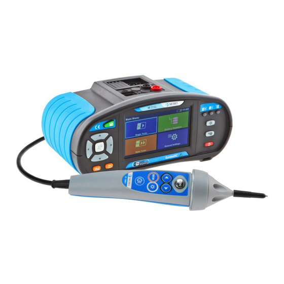
- Page 1 EurotestXC MI 3152 EurotestXC 2,5 kV MI 3152H Instruction manual Version 1.2.2, Code no. 20 752 411...
- Page 2 (European Union) concerning safety and electromagnetic compatibility regulations © 2015 METREL The trade names Metrel, Smartec, Eurotest, Autosequence are trademarks registered or pending in Europe and other countries. No part of this publication may be reproduced or utilized in any form or by any means without...
-
Page 3: Table Of Contents
Battery and charging ....................13 Standards applied ......................14 Instrument set and accessories ..................15 Standard set MI 3152 EurotestXC ................15 Standard set MI 3152H EurotestXC 2,5 kV ..............15 2.2.1 Optional accessories ....................15 Instrument description....................... 16 Front panel ........................16 Connector panel ...................... - Page 4 MI 3152(H) EurotestXC (2,5 kV) Table of contents 4.8.9 Exporting a Workspace .................... 43 Memory Organizer ......................44 Memory Organizer menu ....................44 5.1.1 Measurement statuses ..................... 44 5.1.2 Structure Objects ...................... 45 5.1.3 Operations in Tree menu ..................46 Single tests ..........................
- Page 5 MI 3152(H) EurotestXC (2,5 kV) Table of contents Communication......................... 137 USB and RS232 communication ................137 Bluetooth communication ................... 137 Upgrading the instrument ....................139 Maintenance ........................140 11.1 Fuse replacement ....................... 140 11.2 Cleaning ........................140 11.3 Periodic calibration ..................... 141 11.4...
- Page 6 MI 3152(H) EurotestXC (2,5 kV) Table of contents Battery ......................... 170 Description of commanders ..................170 Operation of commanders ..................171 Appendix D – Structure objects ....................172...
-
Page 7: General Description
1.1.1 Safety warnings In order to reach high level of operator safety while carrying out various measurements using the EurotestXC instrument, as well as to keep the test equipment undamaged, it is necessary to consider the following general warnings: ... -
Page 8: Markings On The Instrument
MI 3152(H) EurotestXC (2,5 kV) General description 1.1.2 Markings on the instrument Read the Instruction manual with special care to safety operation«. The symbol requires an action! Mark on your equipment certifies that it meets European Union requirements for EMC, LVD, and ROHS regulations. -
Page 9: Notes Related To Measurement Functions
MI 3152(H) EurotestXC (2,5 kV) General description 1.1.5 Notes related to measurement functions Insulation resistance The measuring range is decreased if using Plug commander. If a voltage of higher than 30 V (AC or DC) is detected between test terminals, the measurement will not be performed. - Page 10 MI 3152(H) EurotestXC (2,5 kV) General description Z loop, Zs rcd The specified accuracy of tested parameters is valid only if the mains voltage is stable during the measurement. Fault loop impedance (Z loop) measurements will trip an RCD.
-
Page 11: Testing Potential On Pe Terminal
MI 3152(H) EurotestXC (2,5 kV) General description 1.2 Testing potential on PE terminal In certain instances faults on the installation's PE wire or any other accessible metal bonding parts can become exposed to live voltage. This is a very dangerous situation since the parts connected to the earthing system are considered to be free of potential. - Page 12 MI 3152(H) EurotestXC (2,5 kV) General description Connect test cable to the instrument. Connect test leads to the object under test, see Figure 1.1 and Figure 1.2. Touch test probe for at least 2 seconds. If PE terminal is connected to phase voltage the warning message is displayed, instrument buzzer is activated and further measurements are disabled in Z loop, Zs rcd, RCD tests and Auto test sequences.
-
Page 13: Battery And Charging
2100 mAh or above. Unpredictable chemical processes can occur during the charging of battery cells that have been left unused for a longer period (more than 6 months). In this case METREL recommends repeating the charge/discharge cycle at least 2-4 times. ... -
Page 14: Standards Applied
MI 3152(H) EurotestXC (2,5 kV) General description 1.4 Standards applied The EurotestXC instruments are manufactured and tested in accordance with the following regulations: Electromagnetic compatibility (EMC) EN 61326-1 Electrical equipment for measurement, control and laboratory use – EMC requirements Class B (Hand-held equipment used in controlled EM environments) -
Page 15: Instrument Set And Accessories
CD with instruction manual, “Guide for testing and verification of low voltage installations” handbook and PC software Metrel ES Manager. Short instruction manual Calibration Certificate 2.2 Standard set MI 3152H EurotestXC 2,5 kV Instrument MI 3152H EurotestXC 2,5 kV Soft carrying bag ... -
Page 16: Instrument Description
MI 3152(H) EurotestXC (2,5 kV) Instrument description 3 Instrument description 3.1 Front panel Figure 3.1: Front panel 4,3“ COLOR TFT DISPLAY WITH TOUCH SCREEN SAVE key Stores actual measurement result(s) CURSOR keys Navigate in menus RUN key Start / stop selected measurement. -
Page 17: Connector Panel
MI 3152(H) EurotestXC (2,5 kV) Instrument description 3.2 Connector panel Figure 3.2: Connector panel Charger socket USB communication port Communication with PC USB (1.1) port PS/2 communication port Communication with PC RS232 serial port Connection to optional measuring adapters Connection to barcode / RFID reader... -
Page 18: Back Side
MI 3152(H) EurotestXC (2,5 kV) Instrument description 3.3 Back side Figure 3.3: Back view Battery / fuse compartment cover Fixing screws for battery / fuse compartment cover Back panel information label Figure 3.4: Battery and fuse compartment... - Page 19 MI 3152(H) EurotestXC (2,5 kV) Instrument description Fuse F1 M 315 mA / 250 V Fuses F2 and F3 F 4 A / 500 V (breaking capacity 50 kA) Serial number label Battery cells Size AA, alkaline / rechargeable NiMH Figure 3.5: Bottom view...
-
Page 20: Carrying The Instrument
MI 3152(H) EurotestXC (2,5 kV) Instrument description 3.4 Carrying the instrument With the neck-carrying belt supplied in standard set, various possibilities of carrying the instrument are available. Operator can choose appropriate one on basis of his operation, see the following examples: The instrument hangs around operator’s neck... - Page 21 MI 3152(H) EurotestXC (2,5 kV) Instrument description Figure 3.6: First method Figure 3.7: Alternative method Please perform a periodical check of the attachment.
-
Page 22: Instrument Operation
MI 3152(H) EurotestXC (2,5 kV) Instrument operation 4 Instrument operation The EurotestXC instrument can be manipulated via a keypad or touch screen. 4.1 General meaning of keys Cursor keys are used to: select appropriate option. Run key is used to: ... -
Page 23: General Meaning Of Touch Gestures
MI 3152(H) EurotestXC (2,5 kV) Instrument operation 4.2 General meaning of touch gestures Tap (briefly touch surface with fingertip) is used to: select appropriate option; confirm selected option; start and stop measurements. Swipe (press, move, lift) up / down is used to: ... -
Page 24: Virtual Keyboard
MI 3152(H) EurotestXC (2,5 kV) Instrument operation 4.3 Virtual keyboard Figure 4.1: Virtual keyboard Toggle case between lowercase and uppercase. Active only when alphabetic characters keyboard layout selected. Backspace Clears last character or all characters if selected. (If held for 2 s, all characters are selected). -
Page 25: Display And Sound
MI 3152(H) EurotestXC (2,5 kV) Instrument operation 4.4 Display and sound 4.4.1 Terminal voltage monitor The terminal voltage monitor displays on-line the voltages on the test terminals and information about active test terminals in the a.c. installation measuring mode. Online voltages are displayed together with test terminal indication. All three test terminals are used for selected measurement. -
Page 26: Battery Indication
MI 3152(H) EurotestXC (2,5 kV) Instrument operation 4.4.2 Battery indication The battery indication indicates the charge condition of battery and connection of external charger. Battery capacity indication. Battery is in good condition. Battery is full. Low battery. Battery is too weak to guarantee correct result. Replace or recharge the battery cells. - Page 27 MI 3152(H) EurotestXC (2,5 kV) Instrument operation Instrument is overheated. The measurement is prohibited until the temperature decreases under the allowed limit. High electrical noise was detected during measurement. Results may be impaired. Indication of noise voltage above 5 V between H and E terminals during earth resistance measurement.
-
Page 28: Result Indication
MI 3152(H) EurotestXC (2,5 kV) Instrument operation 4.4.4 Result indication Measurement result is inside pre-set limits (PASS). Measurement result is out of pre-set limits (FAIL). Measurement is aborted. Consider displayed warnings and messages. RCD t and RCD I measurements will only be performed if the contact voltage... -
Page 29: Instruments Main Menu
MI 3152(H) EurotestXC (2,5 kV) Instrument operation 4.5 Instruments main menu From the Main menu different main operation menus can be selected. Figure 4.2: Main menu Options Single Tests Menu with single tests, see chapter 6 Single tests. Auto Tests Menu with customized test sequences, see chapter 8 Auto tests. -
Page 30: General Settings
MI 3152(H) EurotestXC (2,5 kV) Instrument operation 4.6 General Settings In the General settings menu general parameters and settings of the instrument can be viewed or set. Figure 4.3: General settings menu Options Language Instrument language selection. Power Save Brightness of LCD, enabling/disabling Bluetooth communication. -
Page 31: Power Save
MI 3152(H) EurotestXC (2,5 kV) Instrument operation Figure 4.4: Language menu 4.6.2 Power Save In this menu different options for decreasing power consumption can be set. Figure 4.5: Power save menu Brightness Setting level of LCD brightness level. Power saving at low level: ca 15% LCD off time Setting LCD off after set time interval. -
Page 32: Settings
MI 3152(H) EurotestXC (2,5 kV) Instrument operation Note: If the batteries are removed the set date and time will be lost. 4.6.4 Settings In this menu different general parameters can be set. Figure 4.7: Settings menu Available selection Description... - Page 33 MI 3152(H) EurotestXC (2,5 kV) Instrument operation system. 4.6.4.1 RCD standard Maximum RCD disconnection times differ in various standards. The trip-out times defined in individual standards are listed below. ½I 2I 5I N N N N General RCDs > 300 ms <...
-
Page 34: Initial Settings
MI 3152(H) EurotestXC (2,5 kV) Instrument operation Table 4.5: Maximum test times related to selected test current for general (non-delayed) RCD ½I Standard 2I 5I N N N N EN 61008 / EN 61009 500 ms 500 ms 200 ms 150 ms... -
Page 35: About
MI 3152(H) EurotestXC (2,5 kV) Instrument operation 4.6.6 About In this menu instrument data (name, serial number, version, fuse version and date of calibration) can be viewed. Figure 4.9: Instrument info screen... -
Page 36: Instrument Profiles
MI 3152(H) EurotestXC (2,5 kV) Instrument operation 4.7 Instrument profiles In this menu the instrument profile can be selected from the available ones. Figure 4.10: Instrument profiles menu The instrument uses different specific system and measuring settings in regard to the scope of work or country it is used. -
Page 37: Workspace Manager Menu
Workspaces are stored on internal data memory on directory WORKSPACES, while Exports are stored on directory EXPORTS. Export files can be read by Metrel applications that run on other devices. Exports are suitable for making backups of important works. To work on the instrument an Export should be imported first from the list of Exports and converted to a Workspace. -
Page 38: Operations With Workspaces
MI 3152(H) EurotestXC (2,5 kV) Instrument operation 4.8.3 Operations with Workspaces Only one Workspace can be opened in the instrument at the same time. The Workspace selected in the Workspace Manager will be opened in the Memory Organizer. Figure 4.12: Workspaces menu Options Marks the opened Workspace in Memory Organizer. - Page 39 MI 3152(H) EurotestXC (2,5 kV) Instrument operation Deletes the selected Export. Refer to chapter 4.8.7 Deleting a Workspace / Export for more information. Imports a new Workspace from Export. Refer to 4.8.8 Importing a Workspace for more information. Opens more options in control panel / expands column.
-
Page 40: Adding A New Workspace
MI 3152(H) EurotestXC (2,5 kV) Instrument operation 4.8.5 Adding a new Workspace Procedure New Workspaces can be added from the Workspace Manager screen. Enters option for adding a new Workspace. Keypad for entering name of a new Workspace is displayed after selecting New. -
Page 41: Opening A Workspace
MI 3152(H) EurotestXC (2,5 kV) Instrument operation 4.8.6 Opening a Workspace Procedure Workspace can be selected from a list in Workspace manager screen. Opens a Workspace in Workspace manager. The opened Workspace is marked with a blue dot. The previously opened Workspace will close automatically. -
Page 42: Importing A Workspace
MI 3152(H) EurotestXC (2,5 kV) Instrument operation Before deleting the selected Workspace / Export the user is asked for confirmation. Workspace / Export is removed from the Workspace / Export list. 4.8.8 Importing a Workspace Select an Export file to be imported from Workspace manager Export list. -
Page 43: Exporting A Workspace
MI 3152(H) EurotestXC (2,5 kV) Instrument operation 4.8.9 Exporting a Workspace Select a Workspace from Workspace manager list to be exported to an Export file. Enters option Export. Before exporting the selected Workspace the user is asked for confirmation. -
Page 44: Memory Organizer
Memory Organizer is a tool for storing and working with test data. 5.1 Memory Organizer menu The data is organized in a tree structure with Structure objects and Measurements. EurotestXC instrument has a multi-level structure. The hierarchy of Structure objects in the tree is shown on Figure 5.1. -
Page 45: Structure Objects
MI 3152(H) EurotestXC (2,5 kV) Memory Organizer finished single test with test results and no status empty single test without test results Overall statuses of Auto tests at least one single test in the Auto test passed and no single test failed... -
Page 46: Operations In Tree Menu
MI 3152(H) EurotestXC (2,5 kV) Memory Organizer One or more measurement result(s) under selected structure object has failed. Not all measurements under selected structure object have been made yet. All measurements under selected structure object are completed but one or more measurement result(s) has failed. - Page 47 MI 3152(H) EurotestXC (2,5 kV) Memory Organizer Recall single test results screen. Starts a new measurement. The instrument goes to the measurement start screen. Refer to chapter 6.1.3 Single test start screen for more information. Clones the measurement. The selected measurement can be copied as an empty measurement under the same Structure object.
- Page 48 MI 3152(H) EurotestXC (2,5 kV) Memory Organizer Parameters and attachments of the Structure object can be viewed or edited. Refer to chapter 5.1.3.3 View / Edit parameters and attachments of a Structure object for more information. Adds a new measurement.
- Page 49 MI 3152(H) EurotestXC (2,5 kV) Memory Organizer 5.1.3.3 View / Edit parameters and attachments of a Structure object The parameters and their content are displayed in this menu. To edit the selected parameter, tap on it or press the key to enter menu for editing parameters.
- Page 50 MI 3152(H) EurotestXC (2,5 kV) Memory Organizer Attachments The name of attachment can be seen. Operation with attachments is not supported in the instrument.
- Page 51 MI 3152(H) EurotestXC (2,5 kV) Memory Organizer 5.1.3.4 Add a new Structure Object This menu is intended to add new structure objects in the tree menu. A new structure object can be selected and then added in the tree menu.
- Page 52 MI 3152(H) EurotestXC (2,5 kV) Memory Organizer Parameters of the Structure object can be edited. Adds the selected structure object in the tree menu. Returns to the tree menu without changes. New object added.
- Page 53 MI 3152(H) EurotestXC (2,5 kV) Memory Organizer 5.1.3.5 Add a new measurement In this menu new empty measurements can be set and then added in the structure tree. The type of measurement, measurement function and its parameters are first selected and then added under the selected Structure object.
- Page 54 MI 3152(H) EurotestXC (2,5 kV) Memory Organizer Select parameter and modify it as described earlier. Refer to chapter 6.1.2 Setting parameters and limits of single tests for more information. Adds the measurement under the selected Structure object in the tree menu.
- Page 55 MI 3152(H) EurotestXC (2,5 kV) Memory Organizer 5.1.3.6 Clone a Structure object In this menu selected structure object can be copied (cloned) to same level in the structure tree. Cloned structure object have same name as original. Procedure Select the structure object to be cloned.
- Page 56 MI 3152(H) EurotestXC (2,5 kV) Memory Organizer 5.1.3.7 Clone a measurement By using this function a selected empty or finished measurement can be copied (cloned) as an empty measurement to the same level in the structure tree. Procedure Select the measurement to be cloned.
- Page 57 MI 3152(H) EurotestXC (2,5 kV) Memory Organizer 5.1.3.8 Copy & Paste a Structure object In this menu selected Structure object can be copied and pasted to any allowed location in the structure tree. Procedure Select the structure object to be copied.
- Page 58 MI 3152(H) EurotestXC (2,5 kV) Memory Organizer The new structure object is displayed. Note The Paste command can be executed one or more times. 5.1.3.9 Cloning and Pasting sub-elements of selected structure object When structure object is selected to be cloned, or copied & pasted, additional selection of its sub-elements is needed.
- Page 59 MI 3152(H) EurotestXC (2,5 kV) Memory Organizer 5.1.3.10 Copy & Paste a measurement In this menu selected measurement can be copied to any allowed location in the structure tree. Procedure Select the measurement to be copied. Select Copy in Control panel.
- Page 60 MI 3152(H) EurotestXC (2,5 kV) Memory Organizer 5.1.3.11 Delete a Structure object In this menu selected Structure object can be deleted. Procedure Select the structure object to be deleted. Select Delete in Control panel. A confirmation window will appear.
- Page 61 MI 3152(H) EurotestXC (2,5 kV) Memory Organizer 5.1.3.12 Delete a measurement In this menu selected measurement can be deleted. Procedure Select a measurement to be deleted. Select Delete in Control panel. A confirmation window will appear. Selected measurement is deleted.
- Page 62 MI 3152(H) EurotestXC (2,5 kV) Memory Organizer 5.1.3.13 Rename a Structure object In this menu selected Structure object can be renamed. Procedure Select the structure object to be renamed. Select Rename in Control panel. Virtual keypad will appear on screen. Enter new text and confirm.
- Page 63 MI 3152(H) EurotestXC (2,5 kV) Memory Organizer 5.1.3.14 Recall and Retest selected measurement Procedure Select the measurement to be recalled. Select Recall results in Control panel. Measurement is recalled. Parameters and limits can be viewed but cannot be edited.
- Page 64 MI 3152(H) EurotestXC (2,5 kV) Memory Organizer Parameters and limits can be viewed and edited. Select Run in Control panel to retest the measurement. Results / sub-results after re-run of recalled measurement. Select Save results in Control panel.
-
Page 65: Single Tests
MI 3152(H) EurotestXC (2,5 kV) Single tests 6 Single tests Single tests can be selected in the main Single tests menu or in Memory organizer main menu and sub-menus. 6.1 Selection modes In Single tests main menu four modes for selecting single tests are available. -
Page 66: Single Test Screens
MI 3152(H) EurotestXC (2,5 kV) Single tests Cross selector This selection mode is the fastest for working with the keypad. Groups of single tests are organized in a row. For the selected group all single tests are displayed and easy accessible with up /down keys. - Page 67 MI 3152(H) EurotestXC (2,5 kV) Single tests Control panel (available options) Parameters (white) and limits (red) Result field: main result(s) sub-result(s) PASS / FAIL indication Voltage monitor with info and warning symbols...
-
Page 68: Setting Parameters And Limits Of Single Tests
MI 3152(H) EurotestXC (2,5 kV) Single tests 6.1.2 Setting parameters and limits of single tests Procedure Select the test or measurement. The test can be entered from: Single tests menu or Memory organizer menu once the empty measurement was created in selected object structure. -
Page 69: Single Test Start Screen
MI 3152(H) EurotestXC (2,5 kV) Single tests Accepts the new parameters and limit values and exits. 6.1.3 Single test start screen Figure 6.2: Single test start screen, example of insulation resistance measurement Options (before test, screen was opened in Memory organizer or Single test main menu): Starts the measurement. -
Page 70: Single Test Screen During Test
MI 3152(H) EurotestXC (2,5 kV) Single tests 6.1.4 Single test screen during test Figure 6.3: Single test is running, example of insulation resistance continuous measurement Operations when test is running: Stops the single test measurement. Proceeds to next step of the measurement (if measurement consists of more steps). -
Page 71: Single Test Result Screen
MI 3152(H) EurotestXC (2,5 kV) Single tests 6.1.5 Single test result screen Figure 6.4: Single test results screen, example of insulation resistance measurement results Options (after measurement is finished) Starts a new measurement. Starts a new continuous measurement (if applicable on long selected single test). - Page 72 MI 3152(H) EurotestXC (2,5 kV) Single tests a new measurement will be saved under the selected Structure object. Opens help screens. Opens screen for changing parameters and limits. Refer to chapter 6.1.2 Setting parameters and limits of single tests for more information.
-
Page 73: Editing Graphs (Harmonics)
MI 3152(H) EurotestXC (2,5 kV) Single tests 6.1.6 Editing graphs (Harmonics) Figure 6.5: Example of Harmonics measurement results Options for editing graphs (start screen or after measurement is finished) Plot edit Opens control panel for editing graphs. Increase scale factor for y-axis. -
Page 74: Help Screens
MI 3152(H) EurotestXC (2,5 kV) Single tests 6.1.7 Help screens Help screens contain diagrams for proper connection of the instrument. Figure 6.6: Examples of help screens Options Goes to previous / next help screen. Back to test / measurement menu. -
Page 75: Recall Single Test Results Screen
MI 3152(H) EurotestXC (2,5 kV) Single tests 6.1.8 Recall single test results screen Figure 6.7: Recalled results of selected measurement, example of insulation resistance recalled results Options Retest Enters starting screen for a new measurement. Refer to chapter 6.1.3 Single test start screen for more information. -
Page 76: Tests And Measurements
MI 3152(H) EurotestXC (2,5 kV) Tests and measurements 7 Tests and measurements See chapter 6.1 Selection modes for instructions on keys and touch screen functionality. 7.1 Voltage, frequency and phase sequence Figure 7.1: Voltage measurement menu Measurement parameters / limits There are no parameters / limits to be set. - Page 77 MI 3152(H) EurotestXC (2,5 kV) Tests and measurements Measurement runs immediately after entering to menu. Save results (optional). Figure 7.4: Examples of Voltage measurement in single-phase system Figure 7.5: Examples of Voltage measurement in three-phase system Measurement results / sub-results...
-
Page 78: R Iso - Insulation Resistance
MI 3152(H) EurotestXC (2,5 kV) Tests and measurements 7.2 R iso – Insulation resistance Figure 7.6: Insulation resistance measurement menu Measurement parameters / limits Uiso Nominal test voltage [50 V, 100 V, 250 V, 500 V, 1000 V, 2500 V*]... - Page 79 MI 3152(H) EurotestXC (2,5 kV) Tests and measurements Measurement procedure Enter the R iso function. Set test parameters / limits. Disconnect tested installation from mains supply and discharge installation as required. Connect test cable to the instrument.
-
Page 80: The Dar And Pi Diagnostic (Mi 3152H Only)
������ ���� = ( 1 min ) �� ������ For additional information regarding PI and DAR diagnostic, please refer to Metrel’s handbook Modern insulation testing. Figure 7.10: Diagnostic test menu Measurement parameters / limits Uiso Nominal test voltage [500 V, 1000 V, 2500 V] Connection diagrams ≤... - Page 81 MI 3152(H) EurotestXC (2,5 kV) Tests and measurements Figure 7.12: Connection of 2.5 kV test lead (U = 2.5 kV) Measurement procedure Enter the Diagnostic test function. Set test parameters / limits. Disconnect tested installation from mains supply and discharge installation as required.
-
Page 82: R Low - Resistance Of Earth Connection And Equipotential Bonding
MI 3152(H) EurotestXC (2,5 kV) Tests and measurements 7.4 R low – Resistance of earth connection and equipotential bonding Figure 7.14: R low measurement menu Measurement parameters / limits Output [LN] Bonding [Rpe, Local] Max. resistance [Off, 0.1 Ω ... 20.0 Ω]... - Page 83 MI 3152(H) EurotestXC (2,5 kV) Tests and measurements Figure 7.16: Examples of R low measurement result Measurement results / sub-results Resistance Result at positive test polarity Result at negative test polarity...
-
Page 84: Continuity - Continuous Resistance Measurement With Low Current
MI 3152(H) EurotestXC (2,5 kV) Tests and measurements 7.5 Continuity – Continuous resistance measurement with low current Figure 7.17: Continuity resistance measurement menu Measurement parameters / limits Sound [On*, Off] Max. resistance [Off, 0.1 Ω ... 20.0 Ω] Limit(R) *Instrument sounds if resistance is lower than the set limit value. -
Page 85: Compensation Of Test Leads Resistance
MI 3152(H) EurotestXC (2,5 kV) Tests and measurements Compensate the test leads resistance if necessary, see section 7.5.1 Compensation of test leads resistance. Disconnect device under test from mains supply and discharge it as required. Connect test leads to device under test, see Figure 7.18. - Page 86 MI 3152(H) EurotestXC (2,5 kV) Tests and measurements Touch the key to compensate leads resistance. Figure 7.21: Result with old and new calibration values...
-
Page 87: Testing Rcds
MI 3152(H) EurotestXC (2,5 kV) Tests and measurements 7.6 Testing RCDs Various test and measurements are required for verification of RCD(s) in RCD protected installations. Measurements are based on the EN 61557-6 standard. The following measurements and tests (sub-functions) can be performed: ... -
Page 88: Rcd Uc - Contact Voltage
MI 3152(H) EurotestXC (2,5 kV) Tests and measurements Figure 7.23: Connecting the Plug commander and the 3-wire test lead 7.6.1 RCD Uc – Contact voltage Test procedure Enter the RCD Uc function. Set test parameters / limits. ... -
Page 89: Rcd T - Trip-Out Time
MI 3152(H) EurotestXC (2,5 kV) Tests and measurements Figure 7.24: Examples of Contact voltage measurement result Test result / sub-results Contact voltage Calculated fault loop resistance 7.6.2 RCD t – Trip-out time Test procedure Enter the RCD t function. -
Page 90: Rcd I - Trip-Out Current
MI 3152(H) EurotestXC (2,5 kV) Tests and measurements 7.6.3 RCD I – Trip-out current The instrument increases the test current in small steps through appropriate range as follows: Slope range RCD type Waveform Notes Start value End value Sine 0.2I 1.1I... -
Page 91: Rcd Auto - Rcd Auto Test
MI 3152(H) EurotestXC (2,5 kV) Tests and measurements 7.7 RCD Auto – RCD Auto test RCD Auto test function performs a complete RCD test (trip-out time at different residual currents, trip-out current and contact voltage) in one set of automatic tests, guided by the instrument. - Page 92 MI 3152(H) EurotestXC (2,5 kV) Tests and measurements Step 3 Step 4 Step 5 Step 6 Step 7 Step 8 Figure 7.27: Individual steps in RCD Auto test Test results / sub-results t I∆N x1, (+) Step 1 trip-out time (I , (+) positive polarity) ...
-
Page 93: Z Loop - Fault Loop Impedance And Prospective Fault Current
MI 3152(H) EurotestXC (2,5 kV) Tests and measurements 7.8 Z loop – Fault loop impedance and prospective fault current Figure 7.28: Z loop menu Measurement parameters / limits Fuse Type Selection of fuse type [gG, NV, B, C, D, K]... - Page 94 MI 3152(H) EurotestXC (2,5 kV) Tests and measurements Measurement procedure Enter the Z loop function. Set test parameters / limits. Connect test cable to the instrument. Connect test leads or Plug commander to the object under test, see Figure 7.29.
-
Page 95: Zs Rcd - Fault Loop Impedance And Prospective Fault Current In System With Rcd
MI 3152(H) EurotestXC (2,5 kV) Tests and measurements 7.9 Zs rcd – Fault loop impedance and prospective fault current in system with RCD Zs rcd measurement prevents trip-out of the RCD in systems with the RCD. Figure 7.31: Zs rcd menu... - Page 96 MI 3152(H) EurotestXC (2,5 kV) Tests and measurements Measurement procedure Enter the Zs rcd function. Set test parameters / limits. Connect test cable to the instrument. Connect test leads or Plug commander to the object under test, see Figure 7.32.
-
Page 97: Z Loop M - High Precision Fault Loop Impedance And Prospective Fault Current
MI 3152(H) EurotestXC (2,5 kV) Tests and measurements 7.10 Z loop m – High precision fault loop impedance and prospective fault current Figure 7.34: Z loop mΩ menu Measurement parameters / limits Fuse Type Selection of fuse type [gG, NV, B, C, D, K]... - Page 98 MI 3152(H) EurotestXC (2,5 kV) Tests and measurements Measurement procedure Enter the Z loop m function. Set test parameters / limits. Connect test leads to A 1143 – Euro Z 290 A adapter and switch it on.
-
Page 99: Z Line - Line Impedance And Prospective Short-Circuit Current
MI 3152(H) EurotestXC (2,5 kV) Tests and measurements 7.11 Z line – Line impedance and prospective short-circuit current Figure 7.38: Z line measurement menu Measurement parameters / limits Fuse Type Selection of fuse type [gG, NV, B, C, D, K]... - Page 100 MI 3152(H) EurotestXC (2,5 kV) Tests and measurements Figure 7.40: Examples of Line impedance measurement result Measurement results / sub-results Line impedance Ipsc Prospective short-circuit current Voltage L-N Resistance of line impedance Reactance of line impedance Prospective short circuit current I is calculated as follows: ...
-
Page 101: Z Line M - High Precision Line Impedance And Prospective Short-Circuit Current
MI 3152(H) EurotestXC (2,5 kV) Tests and measurements 7.12 Z line m – High precision line impedance and prospective short-circuit current Figure 7.41: Z line mΩ menu Measurement parameters / limits Test Type of test [L/N, L/L] Fuse Type Selection of fuse type [gG, NV, B, C, D, K]... - Page 102 MI 3152(H) EurotestXC (2,5 kV) Tests and measurements Start the measurement using button. Save results (optional). Figure 7.43: Examples of high precision Line impedance measurement result Measurement results / sub-results Line impedance Ipsc Standard prospective short-circuit current Imax...
- Page 103 MI 3152(H) EurotestXC (2,5 kV) Tests and measurements �� = √ (1.5 × �� + �� �� �� (��−��)ℎ���� (��−��) (��−��) ������ ��(��−��) �� where ������2�� 0.95; �� = 400 �� ± 10 % �� ��(��−��) (��−��)ℎ���� �� ������ 1.00; ����ℎ������������...
-
Page 104: Voltage Drop
MI 3152(H) EurotestXC (2,5 kV) Tests and measurements 7.13 Voltage Drop The voltage drop is calculated based on the difference of line impedance at connection points (sockets) and the line impedance at the reference point (usually the impedance at the switchboard). - Page 105 MI 3152(H) EurotestXC (2,5 kV) Tests and measurements Press the button to measure Zref. STEP 2: Measuring the Voltage drop Enter the Voltage Drop function. Set test parameters / limits. Connect test cable to the instrument.
- Page 106 MI 3152(H) EurotestXC (2,5 kV) Tests and measurements where: Calculated Voltage drop Zref Impedance at reference point (at origin) Impedance at test point Nominal voltage Rated current of selected fuse (Fuse I) Input voltage range (L-N or L-L) 110 V (93 V U ...
-
Page 107: Earth - Earth Resistance (3-Wire Test)
MI 3152(H) EurotestXC (2,5 kV) Tests and measurements 7.14 Earth – Earth resistance (3-wire test) Figure 7.48: Earth menu Measurement parameters / limits Maximum resistance [Off, 1 ... 5 k] Limit(Re) Connection diagrams Figure 7.49: Resistance to earth, measurement of main installation earthing Figure 7.50: Resistance to earth, measurement of a lighting protection system... - Page 108 MI 3152(H) EurotestXC (2,5 kV) Tests and measurements Start the measurement. Save results (optional). Figure 7.51: Examples of Earth resistance measurement result Measurement results / sub-results Earth resistance Resistance of H (current) probe Resistance of S (potential) probe...
-
Page 109: Earth 2 Clamp - Contactless Earthing Resistance Measurement (With Two Current Clamps)
MI 3152(H) EurotestXC (2,5 kV) Tests and measurements 7.15 Earth 2 clamp – Contactless earthing resistance measurement (with two current clamps) Figure 7.52: Earth 2 clamps menu Measurement parameters / limits Maximum resistance [Off, 1 ... 30 ] Limit(Re) Connection diagram Figure 7.53: Contactless earthing resistance measurement... - Page 110 MI 3152(H) EurotestXC (2,5 kV) Tests and measurements Figure 7.54: Examples of Contactless earthing resistance measurement result Measurement results / sub-results Earth resistance...
-
Page 111: Ro - Specific Earth Resistance
MI 3152(H) EurotestXC (2,5 kV) Tests and measurements 7.16 Ro – Specific earth resistance Figure 7.55: Earth Ro menu Measurement parameters / limits Distance between probes [0.1 m ... 30.0 m] or [1 ft ... 100 Distance Connection diagram Figure 7.56: Specific earth resistance measurement Measurement procedure ... - Page 112 MI 3152(H) EurotestXC (2,5 kV) Tests and measurements Figure 7.57: Example of Specific earth resistance measurement result Measurement results / sub-results Specific earth resistance Resistance of H, E (current) probe Resistance of S, ES (potential) probe...
-
Page 113: Power
MI 3152(H) EurotestXC (2,5 kV) Tests and measurements 7.17 Power Figure 7.58: Power menu Measurement parameters / limits Ch1 clamp type Current clamp adapter [A1018, A1019, A1391] Range Range for selected current clamp adapter A1018 [20 A] A1019 [20 A]... - Page 114 MI 3152(H) EurotestXC (2,5 kV) Tests and measurements Figure 7.60: Example of Power measurement result Measurement results / sub-results Active power Apparent power Reactive power (capacitive or inductive) Power factor (capacitive or inductive) THDu Voltage total harmonic distortion...
-
Page 115: Harmonics
MI 3152(H) EurotestXC (2,5 kV) Tests and measurements 7.18 Harmonics Figure 7.61: Harmonics menu Measurement parameters / limits Ch1 clamp type Current clamp adapter [A1018, A1019, A1391] Range Range for selected current clamp adapter A1018 [20 A] A1019 [20 A]... - Page 116 MI 3152(H) EurotestXC (2,5 kV) Tests and measurements Figure 7.63: Examples of Harmonics measurement results Measurement results / sub-results U:h(i) TRMS voltage of selected harmonic [h0 ... h12] I:h(i) TRMS current of selected harmonic [h0 ... h12] THDu Voltage total harmonic distortion...
-
Page 117: Currents
MI 3152(H) EurotestXC (2,5 kV) Tests and measurements 7.19 Currents Figure 7.64: Current menu Measurement parameters / limits Ch1 clamp type Current clamp adapter [A1018, A1019, A1391] Range Range for selected current clamp adapter A1018 [20 A] A1019 [20 A]... - Page 118 MI 3152(H) EurotestXC (2,5 kV) Tests and measurements Figure 7.66: Examples of Current measurement result Measurement results / sub-results Leakage or load current...
-
Page 119: Isfl - First Fault Leakage Current (Mi 3152 Only)
MI 3152(H) EurotestXC (2,5 kV) Tests and measurements 7.20 ISFL – First fault leakage current (MI 3152 only) Figure 7.67: ISFL measurement menu Measurement parameters / limits Imax(Isc1, Isc2) Maximum first fault leakage current [Off, 3.0 mA ... 19.5 mA] Connection diagrams Figure 7.68: Measurement of highest First fault leakage current with 3-wire test lead... - Page 120 MI 3152(H) EurotestXC (2,5 kV) Tests and measurements Connect test leads to the object under test, see Figure 7.68 and Figure 7.69. Start the measurement. Save results (optional). Figure 7.70: Examples of First fault leakage current measurement result...
-
Page 121: Imd - Testing Of Insulation Monitoring Devices (Mi 3152 Only)
MI 3152(H) EurotestXC (2,5 kV) Tests and measurements 7.21 IMD – Testing of insulation monitoring devices (MI 3152 only) This function checks the alarm threshold of insulation monitor devices (IMD) by applying a changeable resistance between L1/PE and L2/PE terminals. - Page 122 MI 3152(H) EurotestXC (2,5 kV) Tests and measurements Test procedure (MANUAL R, MANUAL I) Enter the IMD function. Set test parameter to MANUAL R or MANUAL I. Set other test parameters / limits. Connect test cable to the instrument.
- Page 123 MI 3152(H) EurotestXC (2,5 kV) Tests and measurements value every time interval selected with timer. To speed up the test press the keys until IMD alarms an insulation failure for L2. Press the or the key. If IMD switches off voltage supply, instrument automatically proceeds to the PASS / FAIL / NO STATUS indication.
-
Page 124: Rpe - Pe Conductor Resistance
MI 3152(H) EurotestXC (2,5 kV) Tests and measurements 7.22 Rpe – PE conductor resistance Figure 7.74: PE conductor resistance measurement menu Measurement parameters / limits Bonding [Rpe,Local] [Yes, No] Max. resistance [Off, 0.1 ... 20.0 ] Limit(Rpe) Connection diagram... - Page 125 MI 3152(H) EurotestXC (2,5 kV) Tests and measurements Measurement procedure Enter the Rpe function. Set test parameters / limits. Connect test cable to the instrument. Connect test leads or Plug commander to the object under test, see Figure 7.75.
-
Page 126: Illumination
MI 3152(H) EurotestXC (2,5 kV) Tests and measurements 7.23 Illumination Figure 7.77: Illumination measurement menu Measurement parameters / limits Limit(E) Minimum illumination [Off, 0.1 lux ... 20 klux] Probe positioning Figure 7.78: LUXmeter probe positioning Measurement procedure Enter the Illumination function. - Page 127 MI 3152(H) EurotestXC (2,5 kV) Tests and measurements Figure 7.79: Examples of Illumination measurement result Measurement results / sub-results Illumination...
-
Page 128: Auto Tests
MI 3152(H) EurotestXC (2,5 kV) Auto tests 8 Auto tests Auto tests perform automatic executing of pre-defined measurement sequences. The following Auto Tests are available: AUTO TT, AUTO TN (RCD), AUTO TN and AUTO IT (MI 3152 only). -
Page 129: Auto Tt - Auto Test Sequence For Tt Earthing System
MI 3152(H) EurotestXC (2,5 kV) Auto tests 8.1 AUTO TT – Auto test sequence for TT earthing system Tests / measurements implemented in AUTO TT sequence Voltage Z line Voltage Drop Zs rcd RCD Uc Figure 8.3: AUTO TT menu... - Page 130 MI 3152(H) EurotestXC (2,5 kV) Auto tests Measurement procedure Enter the AUTO TT function. Set test parameters / limits. Measure the impedance Zref at origin (optional), see chapter 7.13 Voltage Drop. Connect test cable to the instrument.
-
Page 131: Auto Tn (Rcd) - Auto Test Sequence For Tn Earthing System With Rcd
MI 3152(H) EurotestXC (2,5 kV) Auto tests 8.2 AUTO TN (RCD) – Auto test sequence for TN earthing system with RCD Tests / measurements implemented in AUTO TN (RCD) sequence Voltage Z line Voltage Drop Zs rcd Rpe rcd Figure 8.6: AUTO TN (RCD) menu... - Page 132 MI 3152(H) EurotestXC (2,5 kV) Auto tests Measurement procedure Enter the AUTO TN (RCD) function. Set test parameters / limits. Measure the impedance Zref at origin (optional), see chapter 7.13 Voltage Drop. Connect test cable to the instrument.
-
Page 133: Auto Tn - Auto Test Sequence For Tn Earthing System Without Rcd
MI 3152(H) EurotestXC (2,5 kV) Auto tests 8.3 AUTO TN – Auto test sequence for TN earthing system without RCD Tests / measurements implemented in AUTO TN sequence Voltage Z line Voltage Drop Z loop Figure 8.9: AUTO TN menu... - Page 134 MI 3152(H) EurotestXC (2,5 kV) Auto tests Measurement procedure Enter the AUTO TN function. Set test parameters / limits. Measure the impedance Zref at origin (optional), see chapter 7.13 Voltage Drop. Connect test cable to the instrument.
-
Page 135: Auto It - Auto Test Sequence For It Earthing System (Mi 3152 Only)
MI 3152(H) EurotestXC (2,5 kV) Auto tests 8.4 AUTO IT – Auto test sequence for IT earthing system (MI 3152 only) Tests / measurements implemented in AUTO IT sequence Voltage Z line Voltage Drop ISFL Figure 8.12: AUTO IT menu... - Page 136 MI 3152(H) EurotestXC (2,5 kV) Auto tests Measurement procedure Enter the AUTO IT function. Set test parameters / limits. Measure the impedance Zref at origin (optional), see chapter 7.13 Voltage Drop. Connect test cable to the instrument.
-
Page 137: Communication
The instrument is prepared to communicate with the PC. Metrel ES Manager is a PC software running on Windows Vista, Windows 7, Windows 8 and Windows 8.1. 9.2 Bluetooth communication The internal Bluetooth module enables easy communication via Bluetooth with PC and Android devices. - Page 138 Some Android applications automatically carry out the setup of a Bluetooth connection. It is preferred to use this option if it exists. This option is supported by Metrel's Android applications. If this option is not supported by the selected Android application then configure a ...
-
Page 139: Upgrading The Instrument
The firmware upgrade requires internet access and can be carried out from the Metrel ES Manager software with a help of special upgrading software – FlashMe which will guide you through the... -
Page 140: Maintenance
MI 3152(H) EurotestXC (2,5 kV) Maintenance 11 Maintenance Unauthorized persons are not allowed to open the EurotestXC instrument. There are no user replaceable components inside the instrument, except the battery and fuses under back cover. 11.1 Fuse replacement There are three fuses under back cover of the EurotestXC instrument. -
Page 141: Periodic Calibration
MI 3152(H) EurotestXC (2,5 kV) Maintenance Warnings: Do not use liquids based on petrol or hydrocarbons! Do not spill cleaning liquid over the instrument! 11.3 Periodic calibration It is essential that the test instrument is regularly calibrated in order that the technical specification listed in this manual is guaranteed. -
Page 142: Technical Specifications
MI 3152(H) EurotestXC (2,5 kV) Technical specifications 12 Technical specifications 12.1 R iso – Insulation resistance Uiso: 50 V, 100 V and 250 V Riso – Insulation resistance Measuring range according to EN 61557 is 0.15 M … 199.9 M. -
Page 143: Diagnostic Test (Mi 3152H Only)
MI 3152(H) EurotestXC (2,5 kV) Technical specifications 12.2 Diagnostic test (MI 3152H only) Uiso: 500V, 1000 V, 2500 V DAR – Dielectric absorption ratio Measuring range Resolution Accuracy (5 % of reading + 2 digits) 0.01 ... 9.99 0.01 (5 % of reading) 10.0 ... -
Page 144: R Low - Resistance Of Earth Connection And Equipotential Bonding
MI 3152(H) EurotestXC (2,5 kV) Technical specifications 12.3 R low – Resistance of earth connection and equipotential bonding Measuring range according to EN 61557 is 0.16 ... 1999 . R – Resistance Accuracy Measuring range () Resolution () (3 % of reading + 3 digits) 0.00 ... -
Page 145: Rcd Testing
MI 3152(H) EurotestXC (2,5 kV) Technical specifications 12.5 RCD testing General data Nominal residual current (A,AC)....10 mA, 30 mA, 100 mA, 300 mA, 500 mA, 1000 mA Nominal residual current accuracy ..-0 / +0.1I; I = IN, 2IN, 5IN -0.1I... -
Page 146: Rcd T - Trip-Out Time
MI 3152(H) EurotestXC (2,5 kV) Technical specifications RCD t – Trip-out time 12.5.2 Complete measurement range corresponds to EN 61557 requirements. Maximum measuring times set according to selected reference for RCD testing. t N –Trip-out time Measuring range (ms) Resolution (ms) Accuracy 1 ms... -
Page 147: Z Loop - Fault Loop Impedance And Prospective Fault Current
MI 3152(H) EurotestXC (2,5 kV) Technical specifications 12.6 Z loop – Fault loop impedance and prospective fault current Z – Fault loop impedance Measuring range according to EN 61557 is 0.25 ... 9.99 k. Accuracy Measuring range () Resolution () 0.00 ... -
Page 148: Z Line - Line Impedance And Prospective Short-Circuit Current
MI 3152(H) EurotestXC (2,5 kV) Technical specifications 12.8 Z line – Line impedance and prospective short-circuit current Z – Line impedance Measuring range according to EN 61557 is 0.25 ... 9.99 k. Accuracy Measuring range () Resolution () 0.00 ... 9.99 0.01... -
Page 149: Rpe - Pe Conductor Resistance
MI 3152(H) EurotestXC (2,5 kV) Technical specifications 12.10 Rpe – PE conductor resistance RCD: No R – PE conductor resistance Accuracy Measuring range () Resolution () 0.00 ... 19.99 0.01 (5 % of reading + 5 digits) 20.0 ... 99.9 100.0 ... -
Page 150: Earth - Earth Resistance (3-Wire Measurement)
MI 3152(H) EurotestXC (2,5 kV) Technical specifications 12.11 Earth – Earth resistance (3-wire measurement) Re – Earth resistance Measuring range according to EN61557-5 is 2.00 ... 1999 . Accuracy Measuring range () Resolution () 0.00 ... 19.99 0.01 (5 % of reading + 5 digits) 20.0 ... -
Page 151: Ro - Specific Earth Resistance
MI 3152(H) EurotestXC (2,5 kV) Technical specifications 12.13 Ro – Specific earth resistance – Specific earth resistance Accuracy Measuring range (m) Resolution (m) 0.0 ... 99.9 100 ... 999 1.00 k ... 9.99 k 0.01 k See accuracy note 10.0 k ... -
Page 152: Voltage, Frequency, And Phase Rotation
MI 3152(H) EurotestXC (2,5 kV) Technical specifications 12.14 Voltage, frequency, and phase rotation 12.14.1 Phase rotation Nominal system voltage range ....100 V ... 550 V Nominal frequency range ......14 Hz ... 500 Hz Result displayed ........1.2.3 or 3.2.1 12.14.2 Voltage... -
Page 153: Currents
MI 3152(H) EurotestXC (2,5 kV) Technical specifications 12.15 Currents Instrument Maximum voltage on C1 measuring input ..3 V Nominal frequency ........... 0 Hz, 40 Hz ... 500 Hz Ch1 clamp type: A1018 Range: 20 A I1 – Current... -
Page 154: Power
MI 3152(H) EurotestXC (2,5 kV) Technical specifications 12.16 Power Measurement characteristics Function symbols Class according to Measuring range IEC 61557-12 P – Active power 5 % ... 100 % I S – Apparent power 5 % ... 100 % I Q –... -
Page 155: Isfl - First Fault Leakage Current (Mi 3152 Only)
MI 3152(H) EurotestXC (2,5 kV) Technical specifications 12.18 ISFL – First fault leakage current (MI 3152 only) Isc1, Isc2 – First fault leakage current Measuring range (mA) Resolution (mA) Accuracy ±(5 % of reading + 3 digits) 0.0 ... 19.9 Measuring resistance ........ -
Page 156: Illumination
MI 3152(H) EurotestXC (2,5 kV) Technical specifications 12.20 Illumination Illumination (LUXmeter sensor, type B) Specified accuracy is valid for complete operating range. Measuring range (lux) Resolution (lux) Accuracy (5 % of reading + 2 digits) 0.01 ... 19.99 0.01 20.0 ... 199.9 (5 % of reading) -
Page 157: General Data
MI 3152(H) EurotestXC (2,5 kV) Technical specifications 12.21 General data Power supply ........... 6 x 1.2 V Ni-MH battery cells, size AA Operation ..........typical 9 h Charger socket input voltage ....12 V 10 % Charger socket input current ....1000 mA max. -
Page 158: Appendix A - Fuse Table - Ipsc
Appendix A – Fuse table – IPSC MI 3152(H) EurotestXC (2,5 kV) Appendix A – Fuse table – IPSC Fuse type NV Rated Disconnection time [s] current Min. prospective short- circuit current (A) 32.5 22.3 18.7 15.9 65.6 46.4 38.8 31.9... - Page 159 Appendix A – Fuse table – IPSC MI 3152(H) EurotestXC (2,5 kV) Fuse type gG Rated Disconnection time [s] current Min. prospective short- circuit current (A) 32.5 22.3 18.7 15.9 65.6 46.4 38.8 31.9 18.7 102.8 56.5 46.4 26.7 165.8 115.3...
- Page 160 Appendix A – Fuse table – IPSC MI 3152(H) EurotestXC (2,5 kV) Fuse type C Rated Disconnection time [s] current Min. prospective short- circuit current (A) 10.8 21.6 32.4 70.2 86.4 172.8 340.2 Fuse type D Rated Disconnection time [s] current Min.
- Page 161 Appendix A – Fuse table – IPSC MI 3152(H) EurotestXC (2,5 kV) Fuse type K Rated Disconnection time [s] current Min. prospective short- circuit current (A)
-
Page 162: Appendix B - Profile Notes
Appendix B – Profile notes MI 3152(H) EurotestXC (2,5 kV) Appendix B – Profile Notes Instrument supports working with multiple Profiles. This appendix contains collection of minor modifications related to particular country requirements. Some of the modifications mean modified listed function characteristics related to main chapters and others are additional functions. -
Page 163: Profile Finland (Profile Code Alac)
Appendix B – Profile notes MI 3152(H) EurotestXC (2,5 kV) B.2 Profile Finland (profile code ALAC) Modification of Appendix A - Fuse base table changed as follows: Modified Fuse type NV Rated Disconnection time [s] current Min. prospective short- circuit current (A) 40.6... - Page 164 Appendix B – Profile notes MI 3152(H) EurotestXC (2,5 kV) Modified Fuse type gG Rated Disconnection time [s] current Min. prospective short- circuit current (A) 40.6 27.9 23.4 19.9 11.4 48.5 39.9 23.4 128.5 87.5 70.6 33.4 207.3 144.1 120.6 100.9...
- Page 165 Appendix B – Profile notes MI 3152(H) EurotestXC (2,5 kV) Modified Fuse type C Rated Disconnection time [s] current Min. prospective short- circuit current (A) 12.5 12.5 12.5 12.5 17.5 52.5 87.5 162.5 162.5 162.5 162.5 113.8 187.5 187.5 187.5 187.5...
- Page 166 Appendix B – Profile notes MI 3152(H) EurotestXC (2,5 kV) Modified Fuse type K Rated Disconnection time [s] current Min. prospective short- circuit current (A) 18.8 18.8 18.8 18.8 37.5 37.5 37.5 37.5 112.5 112.5 112.5 112.5 187.5 187.5 187.5 187.5...
-
Page 167: Profile Hungary (Profile Code Alad)
Appendix B – Profile notes MI 3152(H) EurotestXC (2,5 kV) B.3 Profile Hungary (profile code ALAD) Fuse type gR added to the fuse tables. Fuse type gR Rated Disconnection time [s] current Min. prospective short- circuit current (A) 31.4 62.8 94.2... - Page 168 Appendix B – Profile notes MI 3152(H) EurotestXC (2,5 kV) Measurement parameters / limits Protection type [No, Automatic disconnection, Class II, Protection type Electrical separation, SELV,PELV] Measurement procedure Enter the Visual Test function. Set test parameters / limits.
-
Page 169: Profile Switzerland (Profile Code Alai)
Appendix B – Profile notes MI 3152(H) EurotestXC (2,5 kV) Test results / sub-results t I∆N x1 (+) Step 1 trip-out time (I , (+) positive polarity) N t I∆N x1 (-) Step 2 trip-out time (I , (-) negative polarity) ... -
Page 170: Appendix C - Commanders (A 1314, A 1401)
If the commander is not used for a long period of time, remove all batteries from the battery compartment. Alkaline or rechargeable Ni-MH batteries (size AAA) can be used. Metrel recommends only using rechargeable batteries with a capacity of 800 mAh or above. -
Page 171: Operation Of Commanders
Appendix C – Commanders MI 3152(H) EurotestXC (2,5 kV) Figure D.4: Front side Plug commander (A 1314) Figure D.5: Back side TEST Starts measurements. TEST Acts also as the PE touching electrode. Left status RGB LED Right status RGB LED... -
Page 172: Appendix D - Structure Objects
Appendix D – Commanders MI 3152(H) Eurotest(H)XC Appendix D – Structure objects Structure elements used in Memory Organizer are instrument’s Profile dependent. Symbol Default name Description Node Node Object Object Dist. board Distribution board Sub D. Board Sub Distribution board Local bonding Local equipotential bonding Water Service... - Page 173 Appendix D – Commanders MI 3152(H) Eurotest(H)XC Data proc. Inst. Protective conductor for Lift Data processing installation Teleph. Inst. Protective conductor for Telephone installation Lightn. prot. syst. Protective conductor for Lightning protection system Antenna inst. Protective conductor for Antenna installation Build.
Need help?
Do you have a question about the EurotestXC and is the answer not in the manual?
Questions and answers