Table of Contents
Advertisement
Quick Links
Advertisement
Table of Contents

Related Manuals for METREL MultiServicerXD MI 3325


Summary of Contents for METREL MultiServicerXD MI 3325
-
Page 1: Instruction Manual
MultiServicerXD MI 3325 Instruction manual Ver. 1.2.4, Code no. 20 752 877... - Page 2 The trade names Metrel , Smartec , Eurotest , Auto Sequence are trademarks registered in Europe and other countries. No part of this publication may be reproduced or utilized in any form or by any means without permission in writing from METREL.
- Page 3 i. About the instruction manual This Instruction manual contains detailed information on the MultiServicerXD, its key features, functionalities and use. It is intended for technically qualified personnel responsible for the product and its use. Please note that LCD screenshots in this document may differ from the actual instrument screens in details due to firmware variations and modifications.
-
Page 4: Table Of Contents
MI 3325 MultiServicerXD Table of contents ABLE OF ONTENTS General description ....................... 8 Warnings and notes ....................8 1.1.1 Safety warnings ....................8 1.1.2 Warnings related to safety of measurement functions ......... 9 1.1.2.1 HV AC, HV AC programmable ................. 9 Differential leak., Ipe leak., Touch leak., Power, Leak’s &... - Page 5 MI 3325 MultiServicerXD Table of contents 4.11.2 Workspace Manager main menu ............... 41 4.11.2.1 Operations with Workspaces ................. 42 4.11.2.2 Operations with Exports ................43 4.11.2.3 Adding a new Workspace ................43 4.11.2.4 Opening a Workspace ................... 44 4.11.2.5 Deleting a Workspace / Export ..............44 4.11.2.6 Importing a Workspace..................
- Page 6 MI 3325 MultiServicerXD Table of contents 6.2.2.1 Compensation of test leads resistance (Continuity, PE conductor (PRCD)) ... 84 6.2.2.2 Limit Calculator ..................... 85 6.2.3 Insulation resistance RPAT (Portable appliance) ..........87 6.2.4 Insulation resistance Rw (Welding equipment) ..........88 6.2.5 Insulation resistance ISO (Installations) .............
- Page 7 MI 3325 MultiServicerXD Table of contents Auto Sequence® result screen ................ 154 7.2.3 ® 7.2.4 Auto Sequence memory screen ..............156 7.2.5 Print label menu....................157 Communications ....................... 158 USB and RS232 communication with PC ..............158 Bluetooth communication ..................158 Bluetooth communication with printers and scanners ..........
- Page 8 Generic tag format ....................193 ® Appendix D Default list of Auto Sequences ..............195 ® Appendix E Programming of Auto Sequences on Metrel ES Manager ......196 ® Auto Sequence editor workspace ................196 ® Managing groups of Auto Sequences ..............197 ®...
-
Page 9: General Description
Use only standard or optional test accessories declared for this instrument and supplied by your distributor! Only test equipment provided or approved by Metrel should be connected to test and communication connectors. Only correctly earthed mains socket outlets shall be used to supply the instrument! ... -
Page 10: Warnings Related To Safety Of Measurement Functions
MI 3325 MultiServicerXD General description Metrel Auto Sequences® are designed as guidance to tests in order to significantly reduce testing time, improve work scope and increase traceability of the tests performed. METREL assumes no responsibility for any Auto Sequence®... -
Page 11: Notes Related To Measurement Functions
MI 3325 MultiServicerXD General description 1.1.3 Notes related to measurement functions Insulation resistance (Riso) If a voltage of higher than 30 V (AC or DC) is detected between TP1 test terminals, the measurement will not be performed. R low If a voltage of higher than 10 V (AC or DC) is detected between TP1 test terminals, the ... -
Page 12: Markings On The Instrument
MI 3325 MultiServicerXD General description The specified accuracy of tested parameters is valid only if the mains voltage is stable during the measurement. Measurement will trip an RCD if the parameter RCD is set to ‘No’. The measurement does not normally trip an RCD if the parameter RCD is set to ‘Yes’. ... -
Page 13: Testing Potential On Tp1-Pe Terminal For Installation Tests
MI 3325 MultiServicerXD General description 1.2 Testing potential on TP1-PE terminal for installation tests In certain instances faults on the installation's PE wire or any other accessible metal bonding parts can become exposed to live voltage. This is a very dangerous situation since the parts connected to the earthing system are considered to be free of potential. - Page 14 MI 3325 MultiServicerXD General description Electromagnetic compatibility (EMC) EN 61326-1 Electrical equipment for measurement, control and laboratory use - EMC requirements – Part 1: General requirements Class B (Portable equipment used in controlled EM environments) Safety (LVD) EN 61010-1 Safety requirements for electrical equipment for measurement, control, and laboratory use –...
- Page 15 MI 3325 MultiServicerXD General description protection for household and similar uses Residual current operated circuit-breakers with integral overcurrent EN 61009 protection for household and similar uses Electrical installations of buildings Part 4-41 Protection for safety – IEC 60364-4-41 protection against electric shock BS 7671 IEE Wiring Regulations (17 edition)
-
Page 16: Instrument Set And Accessories
, 2 m USB cable RS-232 cable CD includes: PC software Metrel ES Manager Instruction manual Quick guide Calibration Certificate 2.2 Optional accessories See the attached sheet for a list of optional accessories that are available on request from your... -
Page 17: Instrument Description
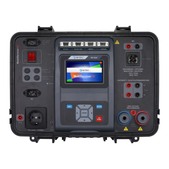
MI 3325 MultiServicerXD Instrument description 3 Instrument description 3.1 Front panel Figure 3.1: Front panel Mains supply connector On / Off switch F1, F2 fuses (F 3.15 A / 250 V) F3, F4 fuses (T 16 A / 250 V) IEC test socket P/S (probe) connector Mains test socket... - Page 18 MI 3325 MultiServicerXD Instrument description Current clamp connectors Warning! Do not connect any voltage source on this input. It is intended only for connection of current clamp with current output. Maximum input current is 30 mA! Colour TFT display with touch screen Control outputs Control inputs Multipurpose RS232-1 port...
-
Page 19: Instrument Operation
MI 3325 MultiServicerXD Instrument operation 4 Instrument operation The instrument can be manipulated via a keypad or touch screen. 4.1 General meaning of keys Cursor keys are used to: select appropriate option Enter key is used to: confirm selected option start and stop measurements Escape key is used to: return to previous menu without changes... -
Page 20: Virtual Keyboard
MI 3325 MultiServicerXD Instrument operation 4.3 Virtual keyboard Figure 4.1: Virtual keyboard Options: Toggle case between lowercase and uppercase. Active only when alphabetic characters keyboard layout selected. Backspace Clears last character or all characters if selected. (If held for 2 s, all characters are selected). Enter confirms new text. -
Page 21: Symbols And Messages
MI 3325 MultiServicerXD Instrument operation Excessive load current through measuring I/O’s, Too low resistance between L and N of tested device, Proper operation of safety relevant internal electronic circuits, Presence of dangerous voltage on PE terminal of TP1 connector. If a safety check fails, an appropriate warning message will be displayed and safety measures will be taken. - Page 22 MI 3325 MultiServicerXD Instrument operation Select YES to proceed with or NO to cancel measurement. Warning for proper connection in PE_conductor measurements. Connection of PRCD’s plug must be changed in order to proceed. Select YES to retry after reconnection with or NO to cancel measurement.
- Page 23 MI 3325 MultiServicerXD Instrument operation The measured leakage (Idiff, Ipe, Itouch) current was higher than 20 mA. Measurement was aborted. Press OK to continue. The load current higher than 16 A is detected. Measurement is aborted. Press OK to continue. The average load current higher than 10 A over the last 5 min test interval is detected.
-
Page 24: Measurement Actions And Messages
MI 3325 MultiServicerXD Instrument operation 4.5.2 Measurement actions and messages Conditions on the input terminals allow starting the measurement; consider other displayed warnings and messages. Conditions on the input terminals do not allow starting the measurement, consider displayed warnings and messages. Proceeds to next step of the measurement. -
Page 25: Result Indication
MI 3325 MultiServicerXD Instrument operation Warning! A very high voltage is / will be present on the instrument output. Warning! Dangerous voltage on TP1-PE input! Stop the activity immediately and eliminate the fault / connection problem before proceeding with any activity! Continuous sound warning and yellow coloured screen is also present. -
Page 26: Auto Sequence® Result Indication
MI 3325 MultiServicerXD Instrument operation 4.5.4 Auto Sequence® result indication ® All Auto Sequence results are inside pre-set limits (PASS). ® One or more Auto Sequence results are out of pre-set limits (FAIL). ® Overall Auto Sequence result without PASS / FAIL indication. -
Page 27: Bluetooth Indication
MI 3325 MultiServicerXD Instrument operation 3-phase measurement terminal screen. IT earthing system terminal indication. Test terminals for Discharging time measurement. 4.5.6 Bluetooth indication Bluetooth communication inactive. Bluetooth communication active. 4.6 Instrument main menu From the instrument Main Menu different main operation menus can be selected. Figure 4.2: Main menu Options Single Tests... -
Page 28: General Settings
MI 3325 MultiServicerXD Instrument operation Memory Organizer Menu for working with and documentation of test data, see chapter 5 Memory Organizer. General Settings Menu for setup of the instrument, see chapter 4.7 General settings. 4.7 General settings In the General Settings menu general parameters and settings of the instrument can be viewed or set. -
Page 29: Language
MI 3325 MultiServicerXD Instrument operation Profiles Selection of available instrument profiles. Refer to chapter 4.10 Instrument profiles for more information. Settings Setting of different system / measuring parameters. Devices Selection of external devices. Refer to chapter 4.9 Devices for more information. -
Page 30: Settings
MI 3325 MultiServicerXD Instrument operation Figure 4.5: Setting data and time menu 4.7.3 Settings Figure 4.6: Settings menu Setting options: Option Description ON – touch screen is active. Touch screen OFF – touch screen is deactivated. ON – sound is active. Keys &... - Page 31 MI 3325 MultiServicerXD Instrument operation verification of protective circuit breakers (fuses, over-current breaking devices, RCDs). The value should be set according to local regulative. PRCD Standard Selection of appropriate standard for PRCD tests. Merge fuses [Yes]: fuse type and parameters set in one function are also kept for other functions! [No]: Fuse parameters will be considered only in function where they have been set.
-
Page 32: Rcd Standard
MI 3325 MultiServicerXD Instrument operation MANUAL] must provide the correct network settings. Otherwise the instrument is automatically assigned an IP address from the local network using the DHCP protocol. Displays the instrument’s IP address. In IP address XXX.XXX.XXX.XXX manual mode, the user should enter the correct value. -
Page 33: Change Password For Hv Functions
MI 3325 MultiServicerXD Instrument operation 120 V 300 ms > 300 ms 230 V 200 ms > 200 ms Table 4.2: Trip-out times according to IEC/HD 60364-4-41 ½I 2I 5I N N N N General RCDs... -
Page 34: Initial Settings
MI 3325 MultiServicerXD Instrument operation Figure 4.7: Change password menu Notes: Default password is 0000. An empty entry disables the password. If password is lost, entry 4648 resets password to default. 4.7.5 Initial Settings In this menu internal Bluetooth module can be initialized and the instrument settings, measurement parameters and limits can be set to initial (factory) values. -
Page 35: About
MI 3325 MultiServicerXD Instrument operation 4.7.6 About In this menu instrument data (name, serial number, firmware (FW) and hardware (HW) version, fuse version and date of calibration) can be viewed. Figure 4.9: Instrument info screen Note: Adapter info is also displayed, if connected. 4.8 User Accounts In this menu user accounts can be managed: ... -
Page 36: Changing User Password, Signing Out
MI 3325 MultiServicerXD Instrument operation Options User signing in: Last signed in user is highlighted and displayed in the first row. Another user can be selected from the User accounts list. Enters User password entry screen. Enter the User password through the on-screen numerical keyboard and confirm User profile screen is opened as presented on Figure 4.11. -
Page 37: Managing Accounts
MI 3325 MultiServicerXD Instrument operation Figure 4.11: User profile menu Options Signed in user is displayed and highlighted on the top of the screen. Sign out current user. Sign in screen appear, see Chapter 4.8.1 Signing in for details. Enters Account manager password entry screen, see Chapter 4.8.1 Signing in for details. - Page 38 MI 3325 MultiServicerXD Instrument operation Administrator can set sign in requirement, change Administrator password and edit user accounts. Appearance of Account manager screen depends on previous settings, see Figure 4.12 below. Figure 4.12: Account manager menu Options User sign in is not required. User sign in is required.
-
Page 39: Edit User Accounts
MI 3325 MultiServicerXD Instrument operation Edit account icon. Enter Edit accounts screen, presented on Figure 4.13. For details see Chapter 4.8.4 Edit user accounts. 4.8.4 Edit user accounts Administrator can add new user and set his password, change user existing password, delete user account and delete all user accounts. -
Page 40: Devices
MI 3325 MultiServicerXD Instrument operation Warning message selection options: YES: confirmation of deletion, all user accounts will be deleted NO: interrupts procedure and return to Edit accounts menu Options: User selected (user is highlighted Set password For selected user, password is set, numerical keyboard appears on the screen. -
Page 41: Instrument Profiles
MI 3325 MultiServicerXD Instrument operation Writing devices Type Sets appropriate writing device (Serial printer, Bluetooth printer), RFID writer). Port Sets/views communication port of selected writing device. Bluetooth device Goes to menu for pairing with selected Bluetooth device. name Bluetooth dongle Initializes Bluetooth Dongle. -
Page 42: Workspace Manager
The Workspace Manager is intended to manage with different Workspaces and Exports stored on the microSD card. 4.11.1 Workspaces and Exports The works with MultiServicerXD MI 3325 can be organized with help of Workspaces and Exports. Exports and Workspaces contain all relevant data (measurements, parameters, limits, structure objects) of an individual work. -
Page 43: Operations With Workspaces
MI 3325 MultiServicerXD Instrument operation Figure 4.17: Workspace manager main menu Options List of Workspaces. Displays a list of Exports Adds a new Workspace. Refer to chapter 4.11.2.3 Adding a new Workspace for more information. List of Exports. Displays a list of Workspaces. 4.11.2.1 Operations with Workspaces Figure 4.18: Workspace manager menu –... -
Page 44: Operations With Exports
MI 3325 MultiServicerXD Instrument operation Deletes the selected Workspace. Refer to chapter 4.11.2.5 Deleting a Workspace / Export for more information. Exports a Workspace to an Export Refer to chapter 4.11.2.7 Exporting a Workspace for more information. 4.11.2.2 Operations with Exports Figure 4.19: Workspace manager Exports menu Options Deletes the selected Export. -
Page 45: Opening A Workspace
MI 3325 MultiServicerXD Instrument operation After confirmation a new Workspace is added to the list of workspaces. 4.11.2.4 Opening a Workspace Workspace can be selected from a list in Workspace manager screen. Opens a Workspace in Workspace manager. -
Page 46: Importing A Workspace
MI 3325 MultiServicerXD Instrument operation Before deleting the selected Workspace Export user asked confirmation. Workspace / Export is deleted from the Workspace / Export list. 4.11.2.6 Importing a Workspace Select an Export file to be imported from Workspace manager Export list. ... -
Page 47: Auto Sequence Groups
MI 3325 MultiServicerXD Instrument operation 4.11.2.7 Exporting a Workspace Select a Workspace from Workspace manager list to be exported to an Export file. Enters option for Export. Before exporting selected Workspace the user is asked for confirmation. Workspace is exported to Export file and is added to the list of Exports. -
Page 48: Operations In Auto Sequence
MI 3325 MultiServicerXD Instrument operation Figure 4.20: Organization of Auto Sequences® on microSD card ® Folders with lists of Auto Sequences are stored in Root\__MOS__\AT on the microSD card ® 4.12.1 Auto Sequence groups menu ® Auto Sequence groups menu can be accessed from General settings menu followed by ®... -
Page 49: Selecting A Group Of Auto Sequences
MI 3325 MultiServicerXD Instrument operation 4.12.1.2 Selecting a group of Auto Sequences® ® A group of Auto Sequences should be ® selected first from the list of Auto Sequence groups. Enters option for selecting a highlighted group. ® Selected group of Auto Sequences marked with a blue dot. -
Page 50: Memory Organizer
The data is organized in a tree structure with Structure objects and Measurements. MultiServicerXD MI 3325 has a multi-level structure. The hierarchy of Structure objects in the tree is shown on Figure 5.1. In Appendix A Structure objects in MultiServicerXD is a list of available structure objects. -
Page 51: Structure Objects
MI 3325 MultiServicerXD Memory Organizer ® at least one single test in the Auto Sequence failed. ® at least one single test in the Auto Sequence carried out and there were no other passed or failed single tests. empty Auto Sequence® with empty single tests. 5.1.2 Structure Objects Each Structure object has: ... -
Page 52: Selecting An Active Workspace In Memory Organizer
MI 3325 MultiServicerXD Memory Organizer more measurement result(s) under selected structure object failed. measurements under selected structure object have been made yet. Figure 5.4: Example of status - Measurements not completed with fail result(s) All measurements under selected structure object are completed but one or more measurement result(s) has failed. -
Page 53: Adding Nodes In Memory Organizer
MI 3325 MultiServicerXD Memory Organizer Choose desired Workspace from the list of Workspaces. Use Select button to confirm selection New Workspace is selected and displayed on the screen. 5.1.4 Adding Nodes in Memory Organizer Structural Elements (Nodes) are used to ease organization of data in the Memory Organizer. One Node is a must;... -
Page 54: Operations In Tree Menu
MI 3325 MultiServicerXD Memory Organizer New Structure Element (Node) will be added. 5.1.5 Operations in Tree Menu In the Memory organizer different actions can be taken with help of the control panel at the right side of the display. Possible actions depend on the selected element in the organizer. 5.1.5.1 Operations on measurements (finished or empty measurements) The measurement must be selected first. -
Page 55: Operations On Structure Objects
MI 3325 MultiServicerXD Memory Organizer Copies & Paste a measurement. The selected measurement can be copied and pasted as an empty measurement to any location in structure tree. Multiple “Paste” is allowed. See chapter 5.1.5.10 Copy & Paste a measurement for more information. Adds a new measurement. -
Page 56: View / Edit Parameters And Attachments Of A Structure Object
MI 3325 MultiServicerXD Memory Organizer Adds a new Structure object. A new Structure object can be added. Refer to chapter 5.1.5.4 Add a new Structure Object for more information. Attachments. Name and link of attachment is displayed. Clones a Structure object. Selected Structure object can be copied to same level in structure tree (clone). - Page 57 MI 3325 MultiServicerXD Memory Organizer Procedure and options Select structure object to be edited. Select Parameters in Control panel. Example of Parameters menu. In menu for editing parameters the parameter’s value can be selected from a dropdown list or entered keypad.
-
Page 58: Add A New Structure Object
MI 3325 MultiServicerXD Memory Organizer View or edit comments Complete comment (if exists) attached to the structure object can be seen on this screen. Press ENTER key or tap on screen to open keypad for entering a new comment. 5.1.5.4 Add a new Structure Object This menu is intended to add new structure objects in the tree menu. - Page 59 MI 3325 MultiServicerXD Memory Organizer Add a new structure object menu. The type of structure object to be added can be selected first from dropdown menu. Only structure objects that can be used in the same level or next sub-level are offered. ...
-
Page 60: Add A New Measurement
MI 3325 MultiServicerXD Memory Organizer New object added. 5.1.5.5 Add a new measurement In this menu new empty measurements can be set and then added in the structure tree. The type of measurement, measurement function and its parameters are first selected and then added under the selected Structure object. -
Page 61: Clone A Structure Object
MI 3325 MultiServicerXD Memory Organizer Last added measurement is offered by default. To select another measurement tap on filed or press the ENTER key to open menu for selecting measurements. Refer to chapters 6.1 Selection of single test Selection Auto ®... - Page 62 MI 3325 MultiServicerXD Memory Organizer Clone Figure 5.11: Clone Structure Object menu...
-
Page 63: Clone A Measurement
MI 3325 MultiServicerXD Memory Organizer Procedure and options Select the structure object to be cloned. Select Clone option from control panel. Clone The Clone Structure object menu is displayed. Sub-elements of the selected structure object can be marked or un-marked for cloning. Refer to chapter 5.1.5.9 Cloning and Pasting sub-elements of selected structure object for more information. -
Page 64: Copy & Paste A Structure Object
MI 3325 MultiServicerXD Memory Organizer The new empty measurement is displayed. 5.1.5.8 Copy & Paste a Structure object Structure object can be copied and pasted to any allowed location in the structure tree. Procedure and options Select the structure object to be copied. ... -
Page 65: Cloning And Pasting Sub-Elements Of Selected Structure Object
MI 3325 MultiServicerXD Memory Organizer The new structure object is displayed. Note: The Paste command can be executed one or more times. 5.1.5.9 Cloning and Pasting sub-elements of selected structure object When structure object is selected to be cloned, or copied & pasted, additional selection of its sub-elements is needed. -
Page 66: Delete A Structure Object
MI 3325 MultiServicerXD Memory Organizer Select Paste option from control panel. Paste A new (empty) measurement is displayed in selected Structure object. 5.1.5.11 Delete a Structure object In this menu selected Structure object can be deleted. Procedure Select the structure object to be deleted. -
Page 67: Rename A Structure Object
MI 3325 MultiServicerXD Memory Organizer Procedure Select a measurement to be deleted. Select Delete option from control panel. Delete A confirmation window will appear. Selected measurement is deleted. Returns to the tree menu without changes. 5.1.5.13 Rename a Structure object In this menu selected Structure object can be renamed. -
Page 68: Recall And Retest Selected Measurement
MI 3325 MultiServicerXD Memory Organizer 5.1.5.14 Recall and Retest selected measurement Procedure Select the measurement to be recalled. Select Recall results in Control panel. Measurement is recalled. Parameters and limits can be viewed but cannot be edited. ... -
Page 69: Searching In Memory Organizer
MI 3325 MultiServicerXD Memory Organizer Retested measurement is saved under same structure object as original one. Refreshed memory structure with the new performed measurement is displayed. 5.1.6 Searching in Memory Organizer In Memory organizer, it is possible to search for different structure objects and parameters. Instrument support data entry with application of Bar code, QR code, NTAG/NFC reader, to search for specific tagged structure element within active workspace. - Page 70 MI 3325 MultiServicerXD Memory Organizer The search can be narrowed on base of test dates / retest dates (from / to). Clears all filters. Sets filters to default value. Clear filters Searches through the Memory Organizer for objects according to the set filters.
- Page 71 MI 3325 MultiServicerXD Memory Organizer Figure 5.13: Search results screen with structure object selected Options Goes to selected location in Memory Organizer. View / edit parameters and attachments. Parameters and attachments of the Structure object can be viewed or edited. Refer to Chapter 5.1.5.3 View / Edit parameters and attachments of a Structure object for more information.
-
Page 72: Single Tests
MI 3325 MultiServicerXD Single tests 6 Single tests 6.1 Selection of single test Single tests can be selected in the Main Single Tests menu or in Memory Organizer’s main and submenus. It is possible to select the area group and two different modes for selecting single tests. -
Page 73: Single Test Screens
MI 3325 MultiServicerXD Single tests For the selected group a submenu with all single tests that belongs to the selected group is displayed. 6.1.1 Single test screens In the Single test screens measuring results, sub-results, limits and parameters of the measurement are displayed. -
Page 74: Setting Parameters And Limits Of Single Tests
MI 3325 MultiServicerXD Single tests Options Starts the measurement. Opens help screens. Refer to chapter 6.1.3 Help screens or more information. Opens menu for changing parameters and limits. Refer to chapter 6.1.1.2 Setting parameters and limits of single tests for more information. 6.1.1.2 Setting parameters and limits of single tests Figure 6.3: Screens in menu for setting Single test parameters and limits Options... -
Page 75: Single Test Screen During Test
MI 3325 MultiServicerXD Single tests Some of limits can be user defined. Selects Custom and tap on it. Numeric keyboard with metric prefixes will open. Enters custom limit value and confirm entry. 6.1.1.3 Single test screen during test Figure 6.4: Single test screen (during measurement) Options (during test) Stops the single test measurement. -
Page 76: Single Test Result Screen
MI 3325 MultiServicerXD Single tests 6.1.1.4 Single test result screen Figure 6.5: Single test result screen Options (after measurement is finished) Starts a new measurement. Saves the result. A new measurement was selected and started from a Structure object in the structure tree: The measurement will be saved under the selected Structure object. -
Page 77: Single Test Memory Screen
MI 3325 MultiServicerXD Single tests 6.1.1.5 Single test memory screen Figure 6.6: Single test memory screen Options Opens menu for viewing parameters and limits. Refer to chapter 6.1.1.2 Setting parameters and limits of single tests for more information. Retest Enters screen with “empty” measurement. 6.1.2 Single test (inspection) screens Visual and Functional inspections can be treated as a special class of tests. -
Page 78: Single Test (Inspection) Start Screen
MI 3325 MultiServicerXD Single tests Figure 6.7: Inspection screen organisation 6.1.2.1 Single test (inspection) start screen Figure 6.8: Inspection start screen Options (inspection screen was opened in Memory organizer or from Single test main menu) Starts the inspection. Opens help screens. Refer to chapter 6.1.3 Help screens for more information. -
Page 79: Single Test (Inspection) Screen During Test
MI 3325 MultiServicerXD Single tests 6.1.2.2 Single test (Inspection) screen during test Figure 6.9: Inspection screen (during inspection) Options (during test) Selects item. Applies a pass status to the selected item or group of items. Applies a fail status to the selected item or group of items. -
Page 80: Single Test (Inspection) Result Screen
MI 3325 MultiServicerXD Single tests Rules for automatic applying of statuses: The parent item(s) can automatically get a status on base of statuses in child items. the fail status has highest priority. A fail status for any item will result in a fail status in all parent items and an overall fail result. -
Page 81: Single Test (Inspection) Memory Screen
MI 3325 MultiServicerXD Single tests An already carried out inspection was selected in structure tree, viewed and then restarted: A new measurement will be saved under the selected Structure object. Adds comment to the measurement. The instrument opens keypad for entering a comment. -
Page 82: Single Test Measurements
MI 3325 MultiServicerXD Single tests Options Opens help screen. Goes to previous / next help screen. Back to test / measurement menu. 6.2 Single test measurements 6.2.1 Visual inspection Figure 6.13: Visual inspection menu Test circuit Figure 6.14: Visual inspection test circuit Visual inspection procedure ... -
Page 83: Continuity
MI 3325 MultiServicerXD Single tests Perform the visual inspection of the appliance / equipment. Apply appropriate ticker(s) to items of inspection. End inspection. Save results (optional). Figure 6.15: Examples of Visual inspection results 6.2.2 Continuity Figure 6.16: Continuity test menu Test results / sub-results R.... - Page 84 MI 3325 MultiServicerXD Single tests Specific options Calibrate - Compensation of test lead / IEC test cable resistance. Refer to chapter 6.2.2.1 for procedure details. Lim. Calculator – Continuity resistance H Limit(R) calculator. Refer to chapter 6.2.2.2 for details. Test circuit Figure 6.17: Continuity MS PE –...
-
Page 85: Compensation Of Test Leads Resistance (Continuity, Pe Conductor (Prcd))
MI 3325 MultiServicerXD Single tests Figure 6.20: Examples of Continuity measurement results 6.2.2.1 Compensation of test leads resistance (Continuity, PE conductor (PRCD)) This chapter describes how to compensate the test leads resistance in Continuity and PE_conductor (PRCD) functions. Compensation can be carried out to eliminate the influence of test leads resistance and the internal resistances of the instrument and adapters on the measured resistance. -
Page 86: Limit Calculator
MI 3325 MultiServicerXD Single tests Figure 6.23: Uncompensated and compensated test result Notes: The compensation value is correct only for the output at which it was carried out. The compensation of test leads is carried out with set test current (I out). ... - Page 87 MI 3325 MultiServicerXD Single tests B: Calculator Continuity and PE_conductor(PRCD) resistance limit is calculated by the formula: �� �� = �� + 0.1Ω �� Where: −8 ρ ....specific resistance of copper 1,68×10 Ωm L ....wire length selected from a list (1 m, 2 m, 3 m, … ,100 m) or Custom numeric entry A ....
-
Page 88: Insulation Resistance Rpat (Portable Appliance)
MI 3325 MultiServicerXD Single tests Custom value is selected from the list. Example of on-screen numeric keyboard – direct H Limit custom value entry. Apply option selection from Limit Calculator options bar automatically overwrite H Limit(R) parameter of selected single test Continuity... -
Page 89: Insulation Resistance Rw (Welding Equipment)
MI 3325 MultiServicerXD Single tests Figure 6.27: Insulation resistance Riso-S measurement procedure Select the Riso function (portable appliance). Set test parameters / limits. Connect device under test to the instrument (see test circuits above). Start measurement. ... -
Page 90: Insulation Resistance Iso (Installations)
Insulation resistance in 3-phase adapter instruction manual. Figure 6.30: Examples of Insulation resistance (Welding equipment) measurement results Note: This test is applicable only with connected METREL 3-phase adapter (A1422). 6.2.5 Insulation resistance ISO (Installations) Figure 6.31: Insulation resistance (Installations) measurement menu Test results / sub-results Riso .. - Page 91 MI 3325 MultiServicerXD Single tests Test parameters Uiso Nominal test voltage [50V, 100V, 250V, 500V, 1000V] Type Riso Type of test [-, L/PE, L/N, N/PE, L/L, L1/L2, L1/L3, L2/L3, L1/N, L2/N, L3/N, L1/PE, L2/PE, L3/PE] Test limits Limit(Riso) Low Limit (Riso) [Off, 0.01 M ... 100 M] Insulation measurement terminals depends on Type Riso setting, see table below.
- Page 92 MI 3325 MultiServicerXD Single tests Connection diagrams Figure 6.32: Connections of 3-wire test lead Measurement procedure Enter the Riso function (installation). Set test parameters / limits. Disconnect tested installation from mains supply and discharge installation as required. ...
-
Page 93: Varistor Test
MI 3325 MultiServicerXD Single tests Figure 6.33: Examples of Insulation resistance (Installations) measurement result 6.2.6 Varistor test A voltage ramp starts from 50 V and rises with a slope of 100 V/s. The measurement ends when the defined end voltage is reached or if the test current exceeds the value of 1 mA. Figure 6.34: Varistor test main menu Test results / sub-results Uac ... - Page 94 MI 3325 MultiServicerXD Single tests Test circuit for Varistor test Figure 6.35: Connection of 3-wire test lead Measurement procedure Enter the Varistor test function. Set test parameters / limits. Connect test cable to the instrument. Connect 3-wire test lead to object under test, see Figure 6.35. ...
-
Page 95: Sub-Leakage (Isub, Isub-S)
MI 3325 MultiServicerXD Single tests 6.2.7 Sub-leakage (Isub, Isub-S) Figure 6.37: Sub Leakage test menus Test results / sub-results Isub ..Sub-leakage current Isub-S ..Sub-leakage current-S Test parameters Type Type of test [Isub, Isub-S, (Isub, Isub-S)] Duration [Off, 2 s … 180 s] Duration Test limits High Limit (Isub) [Off, 0.25 mA …... -
Page 96: Differential Leakage
MI 3325 MultiServicerXD Single tests Measurement can be stopped manually or by timer. Save results (optional). Figure 6.40: Examples of Sub-leakage measurement results Note: When P/S probe is connected during the Sub-leakage measurement, then the current through it is also considered. -
Page 97: Ipe Leakage
MI 3325 MultiServicerXD Single tests Test circuit Figure 6.42: Differential leakage test Differential Leakage measurement procedure Select the Differential Leakage function. Set test parameters / limits. Connect device under test to the instrument (see test circuits above). ... - Page 98 MI 3325 MultiServicerXD Single tests Test parameters Duration [Off, 2 s … 180 s] Duration Change Change status [YES, NO] YES: The instrument measures leakage current in two sequential steps with delay* in between. The phase voltage is firstly applied to the right live output of the mains test socket and secondly to the left live output of the mains test socket.
-
Page 99: Touch Leakage
MI 3325 MultiServicerXD Single tests 6.2.10 Touch Leakage Figure 6.47: Touch Leakage test menu Test results / sub-results Itou ... Touch Leakage current P ....Power Test parameters Duration [Off, 2 s … 180 s] Duration Change Change status [YES, NO] YES: The instrument measures leakage current in two sequential steps with delay* in between. -
Page 100: Welding Circuit Leakage I Leak (W-Pe)
Test circuit, I leak (W-PE) measurement procedure Select the I leak (W-PE) function. Set test parameters / limits. Connect METREL 3-phase adapter (A 1422) to the instrument*. Connect device under test to the 3-phase adapter*. Start measurement. ... -
Page 101: Primary Leakage I
MI 3325 MultiServicerXD Single tests Figure 6.51: Examples of Welding Circuit Leakage measurement results Note: This test is applicable only with connected METREL 3-phase adapter (A1422). 6.2.12 Primary Leakage I primW Figure 6.52: Primary Leakage menu Test results / sub-results Idiff ... - Page 102 Leakage current in 3-phase adapter user manual. Figure 6.53: Examples of Primary Leakage measurement results Note: This test is applicable only with connected METREL 3-phase adapter (A1422). The differential current measurement principle is used for this test. 6.2.13 Leak's & Power Figure 6.54: Leak’s &...
- Page 103 MI 3325 MultiServicerXD Single tests output of the mains test socket and secondly to the left live output of the mains test socket. The phase voltage is applied only to the right live output of the mains test socket. *Delay time [0.2 s … 5 s] Delay Test limits High Limit (P) [Off, 10 W …...
-
Page 104: Power
MI 3325 MultiServicerXD Single tests 6.2.14 Power Figure 6.57: Power measurement menu Test results / sub-results P ....Active power S ....Apparent power Q ....Reactive power PF ..... Power factor THDu ..Total harmonic distortion – voltage THDi ..Total harmonic distortion – current Cos Φ.. -
Page 105: Voltage, Frequency And Phase Sequence
MI 3325 MultiServicerXD Single tests Figure 6.59: Examples of Power measurement results 6.2.15 Voltage, frequency and phase sequence Figure 6.60: Examples of Voltage measurement menu Test results / sub-results Single-phase TN/TT system: Voltage between phase and neutral conductors Ulpe voltage between phase and protective conductors Unpe voltage between neutral and protective conductors Freq... - Page 106 MI 3325 MultiServicerXD Single tests Test parameters System Voltage system [-, 1-phase,3-phase] Limit type Type of limit [Voltage, %] Earthing system Earthing system [TN/TT, IT] Nominal voltage [110 V, 115 V, 190 V, 200 V, 220 V, 230 V, 240 V, 380 Nominal voltage V, 400 V, 415 V] There is no limits to set if System parameter is set to ‘–‘.
- Page 107 MI 3325 MultiServicerXD Single tests Connection diagrams Figure 6.61: Connection of 3-wire test lead and optional adapter in three-phase system Figure 6.62: Connection of Plug test cable or 3-wire test lead in single-phase system Measurement procedure Enter the Voltage function. ...
-
Page 108: Z Loop - Fault Loop Impedance And Prospective Fault Current
MI 3325 MultiServicerXD Single tests 6.2.16 Z loop – Fault loop impedance and prospective fault current Warning! MI 3325 checks voltage on TP1-PE terminal before running test and disables test in case the hazardous live voltage is detected. In this case, immediately remove supply from tested circuit, find, and eliminate problem before any other activity! See chapter 1.2 Testing potential on TP1-PE terminal for installation tests for more information. -
Page 109: Z Loop M - High Precision Fault Loop Impedance And Prospective Fault Current
MI 3325 MultiServicerXD Single tests Test limits Ia(Ipsc) Minimum fault current for selected fuse Connection diagram Figure 6.65: Connection of Plug test cable or 3-wire test lead Measurement procedure Enter the Z loop function. Set test parameters / limits. ... - Page 110 MI 3325 MultiServicerXD Single tests Test results / sub-results Loop impedance Ipsc Standard prospective fault current Imax Maximal prospective fault current Imin Minimal prospective fault current Contact voltage at maximal prospective fault current (contact voltage measured against Probe S if used) Resistance of loop impedance Reactance of loop impedance Ulpe...
- Page 111 MI 3325 MultiServicerXD Single tests Connection diagram Figure 6.68: High precision loop impedance measurement – Connection of A 1143 Figure 6.69: Contact voltage measurement – Connection of A 1143 Measurement procedure Select A 1143 adapter in Settings menu. Enter the Z loop m...
-
Page 112: Zs Rcd - Fault Loop Impedance And Prospective Fault Current In System With Rcd
MI 3325 MultiServicerXD Single tests 6.2.18 Zs rcd – Fault loop impedance and prospective fault current in system with RCD Warning! MI 3325 checks voltage on TP1-PE terminal before running test and disables test in case the hazardous live voltage is detected. In this case, immediately remove supply from tested circuit, find, and eliminate problem before any other activity! See chapter 1.2 Testing potential on TP1-PE terminal for installation tests for more information. - Page 113 MI 3325 MultiServicerXD Single tests Fuse t Maximum breaking time of selected fuse Correction factor Isc [0.2 … 3.0] Isc factor Test Selection of test [-, L-PE, L1-PE, L2-PE, L3-PE] I ∆N Rated RCD residual current sensitivity [10 mA, 15 mA, 30 mA, 100 mA, 300 mA, 500 mA, 1000 mA] RCD type RCD type [AC, A, F, B, B+]...
-
Page 114: Z Line - Line Impedance And Prospective Short-Circuit Current
MI 3325 MultiServicerXD Single tests 6.2.19 Z line – Line impedance and prospective short-circuit current Note! MI 3325 checks voltage on TP1-PE terminal before running test and warning message is presented in case the hazardous live voltage is detected. It is recommended to remove supply from tested circuit, find, and eliminate problem before any other activity! See chapter 1.2 Testing potential on TP1-PE terminal for installation tests for more information. - Page 115 MI 3325 MultiServicerXD Single tests �� = √ (1.5 × �� + �� �� �� ( ��−�� ) ℎ���� (��−��) (��−��) ������ ��(��−��) �� where ������ 0.95; �� = 230 �� ± 10 % �� �� ( ��−�� ) ( ��−�� ) ℎ���� ��...
-
Page 116: Z Line M - High Precision Line Impedance And Prospective Short-Circuit Current
MI 3325 MultiServicerXD Single tests Connection diagram Figure 6.75: Phase-neutral or phase-phase line impedance measurement – connection of Plug test cable or 3-wire test lead Measurement procedure Enter the Z line function. Set test parameters / limits. Connect test cable to the instrument. - Page 117 MI 3325 MultiServicerXD Single tests Test results / sub-results Line impedance Ipsc Standard prospective short-circuit current Imax Maximal prospective short-circuit current Imin Minimal prospective short-circuit current Imax2p Maximal two-phases prospective short-circuit current Imin2p Minimal two-phases prospective short-circuit current Imax3p Maximal three-phases prospective short-circuit current Imin3p Minimal three-phases prospective short-circuit current Resistance of line impedance...
- Page 118 MI 3325 MultiServicerXD Single tests �� = √ �� + �� �� × �� (��−��) (��−��) (��−��) ������ ��(��−��) �� where ������3�� 1.05; �� = 400 �� ± 10 % �� √ 3 �� ( ��−�� ) (��−��) �� ������ 1.10;...
-
Page 119: Z Auto - Auto Test Sequence For Fast Line And Loop Testing
MI 3325 MultiServicerXD Single tests Figure 6.79: Examples of high precision Line impedance measurement result 6.2.21 Z auto - Auto test sequence for fast line and loop testing Warning! MI 3325 checks voltage on TP1-PE terminal before running test and disables test in case the hazardous live voltage is detected. - Page 120 MI 3325 MultiServicerXD Single tests Fuse type Selection of fuse type [gG, NV, B, C, D, K, Off, Custom] Fuse I Rated current of selected fuse Fuse t Maximum breaking time of selected fuse Correction factor Isc [0.2 … 3.0] Isc factor RCD Type RCD type [AC, A, F, B, B+]...
-
Page 121: Voltage Drop
MI 3325 MultiServicerXD Single tests Figure 6.82: Examples of Z auto measurement results 6.2.22 Voltage Drop Note! MI 3325 checks voltage on Zline-PE terminal before running test and warning message is presented in case the hazardous live voltage is detected. It is recommended to remove supply from tested circuit, find, and eliminate problem before any other activity! See chapter 1.2 Testing potential on TP1-PE terminal for installation tests for more information. - Page 122 MI 3325 MultiServicerXD Single tests Zref Impedance at reference point (at origin) Impedance at test point Nominal U or U voltage (see table below) Rated current of selected fuse (Fuse I) Input voltage range (L-N or L-L) (93 V U ...
-
Page 123: Rpe - Pe Conductor Resistance
MI 3325 MultiServicerXD Single tests STEP 2: Measuring the Voltage drop Enter the Voltage Drop function. Set test parameters / limits. Connect test cable to the instrument. Connect 3-wire test lead or Plug test cable to the tested points, see Figure 6.84. ... -
Page 124: R Low - Resistance Of Earth Connection And Equipotential Bonding
MI 3325 MultiServicerXD Single tests Connection diagram Figure 6.87: Connection of Plug test cable or 3-wire test leads Measurement procedure Enter the Rpe function. Set test parameters / limits. Connect test cable to the instrument. Connect 3-wire test lead or Plug test cable to the object under test, see Figure 6.87. ... - Page 125 MI 3325 MultiServicerXD Single tests Result at negative test polarity Test parameters Output [LPE, LN] Bonding [Rpe, Local] R low measurement depends on Output parameter setting, see table below. Output: Test terminals: L and N L and PE Table 6.6: Rlow measuring terminals and Output parameter dependency Test limits Max.
-
Page 126: Compensation Of Test Leads Resistance (Rlow)
MI 3325 MultiServicerXD Single tests 6.2.24.1 Compensation of test leads resistance (Rlow) This chapter describes how to compensate the test leads resistance in Rlow function. Compensation is required to eliminate the influence of test leads resistance and the internal resistances of the instrument on the measured resistance. The test leads compensation is therefore a very important feature to obtain correct result. - Page 127 *For more information refer to chapter 3-phase RCD test in 3-phase AktivGT / Machine adapter Plus A 1322 / A 1422 user manual. Figure 6.95: Examples of PRCD measurement results Note: This test is applicable only with connected METREL 3-phase adapters (A 1322, A 1422).
-
Page 128: Pe Conductor (Prcd)
MI 3325 MultiServicerXD Single tests 6.2.26 PE conductor (PRCD) Figure 6.96: PE conductor (PRCD) test menu Test results / sub-results R....Resistance Test parameters Design Type of PRCD [2 pole, 3 pole, S (3 pole), S+] Duration [Off, 2 s … 180 s] Duration IΔN Nominal current [10 mA, 15 mA, 30 mA, 100 mA, 300 mA]... -
Page 129: Rcd Uc - Contact Voltage
MI 3325 MultiServicerXD Single tests Start measurement. Switch ON the PRCD within 8 s when prompted on the display. Measurement can be stopped manually or by timer. Save results (optional). Figure 6.98: Examples of PE conductor (PRCD) results Note: Mains voltage is applied to the PRCD during the test. - Page 130 MI 3325 MultiServicerXD Single tests mA, 500 mA, 1000 mA] Test Test [-, L/PE, L1/PE, L2/PE, L3/PE] RCD Standard RCD standard selection [EN 61008 / EN 61009, IEC 60364-4-41 TN/IT, IEC 60364-4-41 TT, BS 7671, AS/NZS 3017] Earthing System Earthing system [TN/TT, IT] Test limits Limit Uc Conventional touch voltage limit [12 V, 25 V, 50 V]...
-
Page 131: Rcd T - Trip-Out Time
MI 3325 MultiServicerXD Single tests Figure 6.101: Examples of Contact voltage measurement result 6.2.28 RCD t – Trip-out time Warning! MI 3325 checks voltage on RCD-PE before running test and disables test in case the hazardous live voltage is detected. In this case, immediately remove supply from tested circuit, find, and eliminate problem before any other activity! See chapter 1.2 Testing potential on TP1-PE terminal for installation tests for more information. -
Page 132: Rcd I - Trip-Out Current
MI 3325 MultiServicerXD Single tests 41 TT, BS 7671, AS/NZS 3017] Earthing System Earthing system [TN/TT, IT] Test limits Limit Uc Conventional touch voltage limit [12 V, 25 V, 50 V] Test circuit See Figure 6.100: Connecting the Plug test cable or the 3-wire test lead for details. Test procedure ... - Page 133 MI 3325 MultiServicerXD Single tests Figure 6.104: Trip-out current RCD I test menu Test results / sub-results I∆ Trip-out current I∆ (+) Trip-out current ((+) positive polarity) I∆ (-) Trip-out current ((-) negative polarity) Contact voltage at trip-out current I∆ Uc I∆...
-
Page 134: Rcd Auto - Rcd Auto Test
MI 3325 MultiServicerXD Single tests Figure 6.105: Examples of Trip-out current measurement result 6.2.30 RCD Auto – RCD Auto test Warning! MI 3325 checks voltage on RCD-PE before running test and disables test in case the hazardous live voltage is detected. In this case, immediately remove supply from tested circuit, find, and eliminate problem before any other activity! See chapter 1.2 Testing potential on TP1-PE terminal for installation tests for more information. - Page 135 MI 3325 MultiServicerXD Single tests I ∆N Rated RCD residual current sensitivity [10 mA, 15 mA, 30 mA, 100 mA, 300 mA, 500 mA, 1000 mA] Test Test [-, L/PE, L1/PE, L2/PE, L3/PE] RCD standard [EN 61008 / EN 61009, IEC 60364-4-41 TN/IT, IEC 60364-4- RCD standard 41 TT, BS 7671, AS/NZS 3017] Earthing System Earthing system [TN/TT, IT]...
-
Page 136: Hv Ac
MI 3325 MultiServicerXD Single tests 6.2.31 HV AC IMPORTANT SAFETY NOTES Refer to chapter 1.1 Warnings and notes for more information regarding safe use of the instrument. Requirements from EN 50191 for test installations and safety of withstanding voltage testing shall be applied. Prohibition zone is 30 mm and no part of the body can be closer to tested item. -
Page 137: Hv Ac Programmable
MI 3325 MultiServicerXD Single tests Test circuit Figure 6.109: HV AC measurement HV AC measurement procedure Prepare test setup as mentioned in IMPORTANT SAFETY NOTES above. Select the HV AC function. Set test parameters / limits. Connect HV test leads to HV terminals on the instrument. - Page 138 MI 3325 MultiServicerXD Single tests can be closer to tested item. Two hands must strictly be in operation during testing, one for manipulation with one of the HV test tips and another with manipulation with the HV START button on the MI 3325. ...
- Page 139 MI 3325 MultiServicerXD Single tests Test circuit Figure 6.113: HV AC programmable test HV AC programmable test procedure Prepare test setup as mentioned in IMPORTANT SAFETY NOTES above. Select the HV AC programmable function. Set test parameters / limits. ...
-
Page 140: Polarity
MI 3325 MultiServicerXD Single tests 6.2.33 Polarity Figure 6.115: Polarity test menu Test results / sub-results Result…….Indication of the test [Pass, Description of the fault] Test parameters Mode Test mode [normal, active] ® Status Test status [On, Off] (disable test status within Auto Sequence for K/Di PRCD) LN cross... -
Page 141: Clamp Current
MI 3325 MultiServicerXD Single tests Figure 6.118: Examples of Polarity test Note: Active polarity test is intended for testing cords equipped with (P)RCD or mains operated switches. 6.2.34 Clamp current Figure 6.119: Clamp current test menu Test results / sub-results I .... -
Page 142: No-Load Voltage
MI 3325 MultiServicerXD Single tests Test circuit Figure 6.120: Clamp current test connections Clamp current measurement procedure Select the Clamp current function. Set test parameters / limits. Connect the current clamp to the instrument. Embrace wire(s) that has to be measured with current clamp (see test circuits above). ... -
Page 143: Discharging Time
*For more information refer to chapter Measurements according to IEC/ EN 60974-4 – No load voltage in 3-phase adapter user manual. Figure 6.123: Examples of U No Load measurement results Note: This test is applicable only with connected METREL 3-phase adapter (A 1422). 6.2.36 Discharging time Figure 6.124: Discharging time measurement menu... - Page 144 MI 3325 MultiServicerXD Single tests Test results / sub-results Discharging time Peak value of supply voltage at disconnection time Note: Interpretation of the ‘Repeat’ message: It is not possible to differentiate between a disconnection moment at very low voltage and a machine with a very low discharging time.
-
Page 145: Functional Inspection
MI 3325 MultiServicerXD Single tests Connection diagram Figure 6.126: Discharging time measurement Measurement procedure Enter the Discharging time function. Set test parameters / limits. Connect Residual voltage cable to the instrument and to the device under test (DUT), see Figure 6.126. - Page 146 MI 3325 MultiServicerXD Single tests Test parameters (optional) For the optional Power measurement test, the parameters and limits are the same as set in the Power single test, see chapter 6.2.14 Power. Test circuit Figure 6.129: Functional inspection Functional inspection procedure ...
-
Page 147: Auto Sequences
® Auto Sequences can be pre-programmed on PC with the Metrel ES Manager software and ® uploaded to the instrument. Refer to chapter Appendix E Programming of Auto Sequences ®... -
Page 148: Searching In Auto Sequences® Menu
MI 3325 MultiServicerXD Auto Sequences® ® New Auto Sequence group is selected and all Auto ® Sequences within that group are displayed on the screen. 7.1.2 Searching in Auto Sequences® menu ® ® In Auto Sequences menu it is possible to search for Auto Sequences on base of their Name or Short code. -
Page 149: Organization Of Auto Sequences® In Auto Sequences® Menu
MI 3325 MultiServicerXD Auto Sequences® ® Figure 7.1: Search results screen – Page view (left), Auto Sequence selected (right) Options: Next page. Previous page. ® Goes to location in Auto Sequences menu. ® Goes to Auto Sequence view menu. ® Starts the selected Auto Sequence Note: Search result page consist of up to 50 results. -
Page 150: Organization Of An Auto Sequence
MI 3325 MultiServicerXD Auto Sequences® Options: ® The original Auto Sequence ® A shortcut to the original Auto Sequence ® Starts the selected Auto Sequence ® The instrument immediately starts the Auto Sequence ® Enters menu for detailed view of selected Auto Sequence This option should also be used if the parameters / limits of the selected ®... -
Page 151: Auto Sequence® View Menu (Header Is Selected)
MI 3325 MultiServicerXD Auto Sequences® 7.2.1.1 Auto Sequence® view menu (Header is selected) ® view menu – Header selected Figure 7.3: Auto Sequence Options: ® Starts the Auto Sequence ® Enters Auto Sequence Configurator menu. See chapter 7.2.1.3 Auto Sequence® Configurator menu for details. 7.2.1.2 Auto Sequence®... -
Page 152: Auto Sequence® Configurator Menu
MI 3325 MultiServicerXD Auto Sequences® Options Selects single test measurement. Opens menu for changing parameters and limits of selected measurement. Refer to chapter 6.1.1.2 Setting parameters and limits of single tests for more information. User must decide whether the changes in global parameter(s) apply to all single tests within the selected Auto Sequence®... -
Page 153: Indication Of Loops
MI 3325 MultiServicerXD Auto Sequences® Available settings are organized in groups, each group starts with concerned Single test name. Limit Calculator is referred to Continuity or PE_conductor(PRCD) functions. Refer to Single test description chapter for details of parameters and limits setting / calculation. ®... -
Page 154: Step By Step Execution Of Auto Sequences
MI 3325 MultiServicerXD Auto Sequences® ® 7.2.2 Step by step execution of Auto Sequences ® While the Auto Sequence is running, it is controlled by pre-programmed flow commands. Examples of actions controlled by flow commands are: ® pauses during the Auto Sequence ... - Page 155 ® about programming Auto Sequences refer to Appendix E Programming of Auto Sequences® on Metrel ES Manager. If Inspection Expert mode flow command is set, the Visual inspection screen and Functional inspection screen are displayed for 1 second and an overall PASS is automatically applied at the end of test.
- Page 156 MI 3325 MultiServicerXD Auto Sequences® Options: ® Starts a new Auto Sequence View results of individual measurements. The instrument goes to menu for viewing details of the Auto ® Sequence , see Figure 7.9 below. ® Saves the Auto Sequence results.
- Page 157 MI 3325 MultiServicerXD Auto Sequences® ® Figure 7.9: Menu for viewing details of Auto Sequence and single test results ® Options (menu for viewing details of Auto Sequence and single test results): ® Details of selected single test in Auto Sequence are displayed.
- Page 158 MI 3325 MultiServicerXD Auto Sequences® Print label or goes to Print label menu. Menu is offered only if additional Label Type setting options are available. For more information refer to chapter 7.2.5 Print label menu. Write RFID/NFC tag. Data are written to the RFID/NFC tag. Refer to Appendix C Print labels and write / read RFID/NFC tags for supported tag types.
- Page 159 How to configure a Bluetooth link between instrument and Android device Switch On the instrument. Some Android applications automatically carry out the setup of a Bluetooth connection. It is preferred to use this option if it exists. This option is supported by Metrel's Android...
- Page 160 8.3 Bluetooth communication with printers and scanners MultiServicerXD instrument can communicate with supported Bluetooth printers and scanners. Contact Metrel or your distributor which external devices and functionalities are supported. See Chapter 4.9 Devices for details how to set the external Bluetooth devices.
- Page 161 MI 3325 MultiServicerXD Communications 8.6 Connections to test adapters 8.6.1 Active 3 Phase Adapter /Plus (A 1322 / A 1422) Figure 8.1: Connection of Active 3 Phase Adapter / plus (A 1322 / A 1422) Note: See 3-phase adapter A 1322 / A 1422 user manual for more details. 8.6.2 Euro Z 290A adapter A 1143 Figure 8.2: Connection of the Euro Z 290 A adapter A 1143 Note:...
- Page 162 MI 3325 MultiServicerXD Communications 8.7 INPUTS The DB9 connector INPUTS is intended for connection of external control signals. Figure 8.4: INPUTS connector - pin layout Legend: Description Type EXTERNAL Input for Remote control pedal Input low: < 1 V d.c. against earth mode Input high: >...
- Page 163 MI 3325 MultiServicerXD Communications Legend: Description Type OUT_1 Control output 1 NO relay, Umax: 24V, Imax: 1.5 A Output low: open contact Output high: closed contact OUT_2 Control output 2 OUT_3 Control output 3 OUT_4 Control output 4 +5 V Supply for inputs...
- Page 164 This enables to keep the instrument up to date even if the standards or regulations change. The firmware upgrade requires internet access and can be carried out from the Metrel ES Manager software with a help of special upgrading software – FlashMe which will guide you through the...
- Page 165 MI 3325 MultiServicerXD Maintenance 10 Maintenance 10.1 Periodic calibration It is essential that all measuring instruments are regularly calibrated in order for the technical specification listed in this manual to be guaranteed. We recommend an annual calibration. 10.2 Fuses There are four fuses on the front panel: F1, F2: F 3.15 A / 250 V / (20 ...
-
Page 166: Technical Specifications
MI 3325 MultiServicerXD Technical specifications 11 Technical specifications 11.1 HV AC, HV AC programmable Voltage a.c. Range Resolution Accuracy (3 % of reading) 0 V ... 1999 V (3 % of reading) 2.00 kV ... 5.99 kV 10 V Current a.c. (apparent) Range Resolution Accuracy... - Page 167 MI 3325 MultiServicerXD Technical specifications 0.75 6 Operating range (acc. to EN 61557-4) ..... 0.08 Ω … 199.9 Test currents ........... 0.2A, 4 A, 10A, 25A Current source (at nominal mains voltage, use of standard accessories) ................ > 0.2 A at R < 8 Ω ................
- Page 168 MI 3325 MultiServicerXD Technical specifications Test terminals: Socket LN – Socket PE, P/S Isub Socket LN – P/S Isub-S 11.5 Differential Leakage current Differential leakage current Range Resolution Accuracy (3 % of reading + 5 D) 0.00 mA … 19.99 mA Idiff 0.01 mA Power (active)
- Page 169 MI 3325 MultiServicerXD Technical specifications 2.00 mA … 19.99 mA (5 % of reading) 0.01 mA Power (active) Range Resolution Accuracy (5 % of reading + 5 D) 0.00 W…19.99 W 0.01 W 20.0 W…199.9 W 5 % of reading 0.1 W ...
- Page 170 MI 3325 MultiServicerXD Technical specifications Total Harmonic Distortion (current) Range Resolution Accuracy 0 mA … 999 mA (5 % of reading + 5 D) THDI 1 mA 5 % of reading 1.00 A ... 16.00 A 0.01 A Cos Φ Range Resolution Accuracy...
- Page 171 MI 3325 MultiServicerXD Technical specifications Power factor Range Resolution Accuracy 0.00i … 1.00i (5 % of reading + 5 D) 0.01 0.00c … 1.00c Total Harmonic Distortion (voltage) Accuracy Range Resolution (5 % of reading + 5 D) 0.0 % … 99.9 % THDU 0.1 % Total Harmonic Distortion (current)
-
Page 172: Rcd Testing
MI 3325 MultiServicerXD Technical specifications 11.10 PRCD Refer to chapter Technical specifications in 3-phase adapter instrument user manual. 11.11 PE conductor (PRCD) PE conductor (Type = 2 pole, 3 pole, S(3 pole), S+) Range Resolution Accuracy 0.00 … 19.99 0.01 ... - Page 173 MI 3325 MultiServicerXD Technical specifications ............. applicable AC type........... sine wave test current A, F types…… ........pulsed current B, B+ types ..........smooth DC current Test terminals: All RCD testing results and sub-results 11.12.1 RCD Uc – Contact voltage Measuring range according to EN 61557 is 20.0 V ...
- Page 174 MI 3325 MultiServicerXD Technical specifications Trip out-time Range Resolution Accuracy 3 ms 0 ms ... 300 ms 1 ms t I Uc I – Contact voltage Range Resolution Accuracy (-0 % / +15 %) of reading 10 digits 0.0 V ... 19.9 V 0.1 V Uc I...
- Page 175 MI 3325 MultiServicerXD Technical specifications 11.15 Insulation resistance Riso (welding equipment) Riso Range Resolution Accuracy (3 % of reading + 2 D) 0.08 M … 19.99 M 0.01 M Riso 5 % of reading 20.0 M … 99.9 M 0.1 M...
- Page 176 MI 3325 MultiServicerXD Technical specifications 11.19.2 Voltage Voltage Range Resolution Accuracy Uln, Ulpe, Unpe, (2 % of reading + 2 digits) U1pe, U2pe, 0 V ... 550 V U12, U13, U23 Result type ..........True r.m.s. (TRMS) Nominal frequency range ....... 0 Hz, 14 Hz ... 500 Hz 11.19.3 Frequency Frequency Range...
- Page 177 MI 3325 MultiServicerXD Technical specifications Nominal voltages Uiso ......50 V , 100 V , 250 V , 500 V , 1000 V Open circuit voltage ........ -0 %, +20 % of nominal voltage 1 k/V Measuring current ........min. 1 mA at R Short circuit current .......
- Page 178 MI 3325 MultiServicerXD Technical specifications 11.23 Z loop – Fault loop impedance and prospective fault current Fault loop impedance Range Resolution Accuracy 0.12 ... 9.99 0.01 (5 % of reading + 5 digits) 10.0 ... 99.9 0.1 ...
- Page 179 MI 3325 MultiServicerXD Technical specifications Prospective fault current Range Resolution Accuracy 0.00 A ... 9.99 A 0.01 A 10.0 A ... 99.9 A 0.1 A Consider accuracy of fault loop resistance Ipsc 100 A ... 999 A measurement 1.00 kA ... 9.99 kA 10 A 10.0 kA ...
- Page 180 MI 3325 MultiServicerXD Technical specifications 11.26 Z auto Refer to following chapters for detailed technical specification: 11.19.2 Voltage 11.29 Voltage Drop 11.25 Z line – Line impedance and prospective short-circuit current 11.24 Zs rcd – Fault loop impedance and prospective fault current in system with RCD 11.12.1 RCD Uc –...
- Page 181 MI 3325 MultiServicerXD Technical specifications Input resistance ..........20 M Test terminals: All results 11.31 Rpe – PE conductor resistance RCD: No R – PE conductor resistance Range Resolution Accuracy 0.00 ... 19.99 0.01 (5 % of reading + 5 digits) 20.0 ...
- Page 182 MI 3325 MultiServicerXD Technical specifications Power supply ........... Class I HV output ............5 kV a.c. double insulation Pollution degree ..........2 Degree of protection ........IP 54 (closed case) IP 40 (open case) IP 20 (mains test socket) Case ..............Shock proof plastic / portable INPUTS ............
- Page 183 MI 3325 MultiServicerXD Appendix A Appendix A Structure objects in MultiServicerXD Structure elements used in Memory Organizer are instrument’s Profile dependent. Symbol Default name Description Node Node Project Project Location Location Client Client Element Universal element Appliance Appliance (basic description) Appliance FD Appliance (full description) Welding device...
- Page 184 MI 3325 MultiServicerXD Appendix B Appendix B Profile Notes Instrument supports working with multiple Profiles. This appendix contains collection of minor modifications related to particular country requirements. Some of the modifications mean modified listed function characteristics related to main chapters and others are additional functions.
- Page 185 MI 3325 MultiServicerXD Appendix B B.2 Profile Hungary (AUAE) Fuse type gR added to the fuse tables. Refer to Fuse tables guide for detailed information on fuse data. Modifications in chapter 6.2.30 RCD Auto – RCD Auto test Added tests with multiplication factor 2. Modification of RCD Auto test procedure RCD Auto test inserted steps Notes...
- Page 186 MI 3325 MultiServicerXD Appendix B B.4 Profile France (AUAC) Modifications in chapters: 6.2.27 RCD Uc – Contact voltage, 6.2.28 RCD t – Trip-out time 6.2.29 RCD I – Trip-out current 6.2.30 RCD Auto – RCD Auto test 6.2.18 Zs rcd – Fault loop impedance and prospective fault current in system with RCD 6.2.21 Z auto - Auto test sequence for fast line and loop testing 650 mA added in the I N parameter in Test Parameters / Limits section as follows: I N...
- Page 187 MI 3325 MultiServicerXD Appendix B is replaced with Option Description Z factor Impedance correction scaling factor [1, 0.80], Default value: 0.80 The value should be set according to local regulative. Default value of RCD Standard parameter is changed to BS 7671. Modifications in chapters: 6.2.16 Z loop –...
- Page 188 MI 3325 MultiServicerXD Appendix B Scaling factor where: Zlim ......Maximum loop / line impedance for selected fuse (according to BS 7671) Scaling factor .... Impedance correction factor (Z factor) Un ......Nominal U voltage L-PE Modifications in chapter 6.2.27 RCD Uc – Contact voltage: Added new sub-result: Test results / sub-results Rmax...
- Page 189 MI 3325 MultiServicerXD Appendix B 6.2.21 Z auto - Auto test sequence for fast line and loop testing 6.2.22 Voltage Drop Test parameters Fuse Type Selection of fuse type [gG, NV, B, C, D, K, Off, Custom] Correction factor Isc [0.2 … 3.0] Isc factor Test limits Ia(Ipsc)
- Page 190 MI 3325 MultiServicerXD Appendix B Figure B.5: Example of Trip-out time measurement result with enabled Random phase Modifications in chapter 6.2.30 RCD Auto – RCD Auto test: Added new test parameter: Test parameter Random phase [No, Yes] Added tests with multiplication factor 2. Modification of RCD Auto test procedure RCD Auto test inserted steps Notes...
- Page 191 MI 3325 MultiServicerXD Appendix B t I∆N x0.5 (-) =½I Step 8 trip-out time (I , (-) negative polarity) N I∆ (+) Step 9 trip-out current ((+) positive polarity) I∆ (-) Step 10 trip-out current ((-) negative polarity) Contact voltage for rated I N...
- Page 192 – barcode or QR code – in addition. The instrument supports RFID / NFC reader / writer device; tag type supported is NTAG216. Please check with Metrel or distributor which printers and labels are supported in your MultiServicerXD instrument.
- Page 193 MI 3325 MultiServicerXD Appendix C Label Form size Tag content Data1 label Data 2 label type W x H arrangement (mm) Classic Barcode Test code, appliance ID Appliance ID Text Test code, appliance ID, Appliance ID, test or test or retest date, status, retest date, status, user user Test code, appliance ID,...
- Page 194 MI 3325 MultiServicerXD Appendix C label is intended to mark supply cords. Data not available will not be printed on the label. Test or Retest date: is set in the General Settings => Devices => Writing devices menu. ...
- Page 195 MI 3325 MultiServicerXD Appendix C Notes: Data not available will not be printed on the label. Object without appended Auto Sequence® test has no status! If Auto Sequence® was modified, its short code is marked with asterisk (*). ...
- Page 196 MI 3325 MultiServicerXD Appendix D ® Appendix D Default list of Auto Sequences Default list of Auto Sequences® for MI 3325 MultiServicerXD instrument is available on Metrel home page: http://www.metrel.si...
- Page 197 Appendix E Programming of Auto Sequences on Metrel ES Manager ® ® The Auto Sequence editor is a part of the Metrel ES Manager software. In Auto Sequence ® editor Auto Sequences can be pre-programmed and organized in groups, before uploaded to the instrument.
- Page 198 MI 3325 MultiServicerXD Appendix E ® Figure E.2: Example of an Auto Sequence header Figure E.3: Example of a measurement step ® Figure E.4: Example of an Auto Sequence result ® E.2 Managing groups of Auto Sequences ® ® The Auto Sequences can be divided into different user defined groups of Auto Sequences ®...
- Page 199 MI 3325 MultiServicerXD Appendix E File operation options: ® Opens a file (Group of Auto Sequences ® Creates a new file (Group of Auto Sequences ® Saves / Saves as the opened Group of Auto Sequences to a file. ® Closes the file (Group of Auto Sequences ®...
- Page 200 MI 3325 MultiServicerXD Appendix E “Drag and drop” functionality is equivalent to “cut” and “paste” in a single move. DRAG & DROP move to folder insert ® E.2.1 Auto Sequence Name, Description and Image editing ® When EDIT function is selected on Auto Sequence , menu for editing presented on Figure appear on the screen.
- Page 201 Result step. E.3.1 Single tests Single tests are the same as in Metrel ES Manager Measurement menu. Limits and parameters of the measurements can be set. Results and sub-results can’t be set. E.3.2 Flow commands Flow commands are used to control flow of the measurements.
- Page 202 MI 3325 MultiServicerXD Appendix E ® individual Single test results are stored in the Auto Sequence result as if they were programmed as independent measuring steps. ® E.4 Creating / modifying an Auto Sequence ® If creating a new Auto Sequence from scratch, the first step (Header) and the last step (Result) are offered by default.
- Page 203 MI 3325 MultiServicerXD Appendix E A Pause command with text message or picture can be inserted anywhere in the measuring steps. Warning icon can be set alone or added to text message. Arbitrary text message can be entered in prepared field Text of menu window. Parameters: Pause type Show text and/or warning (...
- Page 204 MI 3325 MultiServicerXD Appendix E Drives external lamps through OUT_1 and OUT_2 outputs. Works only in HV & HV programmable functions. Red lamp (OUT_1) ON means that the instrument is ready for HV test. Red lamp turns on before first flow command in step that contains HV test. Red lamp turns off after end of the HV test.
- Page 205 MI 3325 MultiServicerXD Appendix E No notifications mode Instrument skips pre-test warnings (see chapter 4.5 Symbols and messages for more information). Parameters On – enables No notifications mode State Off – disables No notifications mode Appliance info ® Instrument enables to automatically add the appliance name to the Auto Sequence Parameters Repeat Setting Repeat:...
- Page 206 MI 3325 MultiServicerXD Appendix E Parameters On – enables automatic settings of tickers in Visual and Functional tests. State Off – disables automatic settings of tickers in Visual and Functional tests. Operation after end of test ® This flow command controls the proceeding of the Auto Sequence in regard to the measurement results.
- Page 207 MI 3325 MultiServicerXD Appendix E application of Custom Inspections as a single test within Auto Sequence® group, appropriate file containing specific Custom Inspection should be opened first. E.6.1 Creating and editing Custom Inspections Custom Inspection Editor workspace is entered by selecting icon from Auto Sequences®...
- Page 208 MI 3325 MultiServicerXD Appendix E and Type can be edited – changed. Remove selected custom inspection. To select inspection, click to the inspection Name field. To remove it, select icon from editor main menu. Before removal, user is asked to confirm deletion. Edit Name and Scope of Inspection Inspection Name edit: Click to the Inspection Name field to start editing it.
- Page 209 E.6.2 Applying Custom Inspections Custom inspections can be applied in Auto Sequences®. Direct assignment of Custom inspection to the Metrel ES manager structure objects is not possible. After custom created Inspection Data file is opened, available inspections are listed in Custom ®...
Need help?
Do you have a question about the MultiServicerXD MI 3325 and is the answer not in the manual?
Questions and answers