Table of Contents
Advertisement
Quick Links
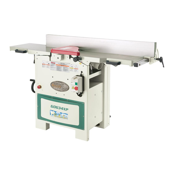
model g0634z/g0634Xp
Jointer/planer
combination machine
oWner's manual
(For models manufactured since 01/11)
Copyright © april, 2007 By grizzly industrial, inC., revised septemBer, 2018 (wk)
Warning: no portion of this manual may be reproduced in any shape
or form Without the Written approval of grizzly industrial, inc.
#Bl8977 printed in taiwan
v3.09.18
Advertisement
Table of Contents


Need help?
Do you have a question about the G0634XP and is the answer not in the manual?
Questions and answers