Table of Contents
Advertisement
Quick Links
The Model G0634X is the same machine as the Model G0634Z/G0634XP except for the V-helical cutterhead.
Except for the differences noted in this insert, all other content in the Model G0634Z/G0634XP owner's
manual applies to this machine.
: To reduce the risk of serious injury, you MUST read and understand this insert—and the
entire Model G0634Z/G0634XP manual—BEFORE assembling, installing, or operating this machine!
If you have any questions about this manual insert or the differences between the Model G0634X and the Model
G0634Z/G0634XP, contact our Technical Support at (570) 546-9663 or email techsupport@grizzly.com.
Machine Inventory
After all the parts have been removed from the
crate, you should have the following items:
Common Components (Figure 1)
A. Jointer/Planer Assembly (Not Shown) ........ 1
B. Push Blocks ................................................ 2
C. Cutterhead Guard Assembly ...................... 1
D. Hardware and Tools (Not Shown)
— Wrenches 8/10, 12/14mm ................1 Ea
— Hex Wrenches 3, 4mm, 2.5mm .......1 Ea
B
Figure 1. Common components.
WARNING: NO PORTION OF THIS MANUAL MAY BE REPRODUCED IN ANY SHAPE
OR FORM WITHOUT THE WRITTEN APPROVAL OF GRIZZLY INDUSTRIAL, INC.
Qty
C
COPYRIGHT © NOVEMBER, 2020 BY GRIZZLY INDUSTRIAL, INC.
#KS21436 PRINTED IN TAIWAN
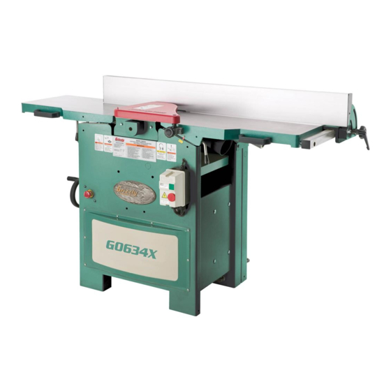
MODEL G0634X
12" JOINTER/PLANER
w/V-HELICAL CUTTERHEAD
MANUAL INSERT
For Machines Mfd. Since 11/20
and Owner's Manual Revised 02/20
V-Helical Cutterhead Hardware (Figure
E. V-Helical Cutterhead Hardware
— Indexable Inserts 15 x 15 x 2.5mm ........ 5
— Flat Head T20 Torx Screws M6-1 x 16 .. 10
— Torx Bits T20 ......................................... 5
— T-Handle T20 Torx Driver ...................... 1
Figure 2. V-helical cutterhead hardware.
2
)
E
Advertisement
Table of Contents

Related Manuals for Grizzly G0634X


Summary of Contents for Grizzly G0634X
- Page 1 Model G0634Z/G0634XP manual—BEFORE assembling, installing, or operating this machine! If you have any questions about this manual insert or the differences between the Model G0634X and the Model G0634Z/G0634XP, contact our Technical Support at (570) 546-9663 or email techsupport@grizzly.com.
- Page 2 Bevel Jointing ..............................0 - 45 deg. Maximum Width of Cut .............................12 in. Maximum Depth of Cut ............................1/8 in. Number of Cuts Per Minute ............................20,136 Minimum Stock Length .............................12 in. Minimum Stock Thickness ............................1/4 in. Model G0634X Page 1 of 3 Model G0634X (Mfd. Since 11/20)
- Page 3 Measurement Scale (Planer) ........................... Inch/Metric Other Specifications: Country of Origin ................................Taiwan Warranty ................................... 1 Year Approximate Assembly & Setup Time ........................30 Minutes Serial Number Location ..............................ID Label Page 2 of 3 Model G0634X Model G0634X (Mfd. Since 11/20)
- Page 4 PARTS We do our best to stock replacement parts when possible, but we cannot guarantee that all parts shown are available for purchase. Call (800) 523-4777 or visit www.grizzly.com/parts to check for availability. Stand 29-5 29-3 29-1 12-3 29-4 29-2...
- Page 5 P0634X049 KNOB BOLT 1/4-20 X 1/2, 6-LOBE, D7/8 P0634X019 DEPTH SCALE P0634X051 CABLE CLAMP P0634X020 LIMIT SWITCH CORD P0634X052 HEX NUT 10-24 BUY PARTS ONLINE AT GRIZZLY.COM! Model G0634X (Mfd. Since 11/20) Scan QR code to visit our Parts Store.
- Page 6 CAP SCREW 5/16-18 X 1 P0634X708 RIVET 4 X 7 PUSH, NYLON P0634X124 CAP SCREW 3/8-16 X 1-1/4 P0634X710 WAVY WASHER 12MM P0634X125 HEX NUT 5/16-18 BUY PARTS ONLINE AT GRIZZLY.COM! Model G0634X (Mfd. Since 11/20) Scan QR code to visit our Parts Store.
- Page 7 SET SCREW M5-.8 X 6 P0634X218 SUPPORT P0634X243 FLANGE SCREW 10-24 X 1/2 P0634X219 ANTIKICKBACK FINGER P0634X244 HEX NUT 10-24 P0634X220 SPACER BUY PARTS ONLINE AT GRIZZLY.COM! Model G0634X (Mfd. Since 11/20) Scan QR code to visit our Parts Store.
- Page 8 CAP SCREW 5/16-18 X 2-1/2 P0634X319 SPROCKET 19T P0634X340 PLASTIC KNOB P0634X320 INT RETAINING RING 22MM P0634X341 SPACER 8.6 X 15 X 18.6MM BUY PARTS ONLINE AT GRIZZLY.COM! Model G0634X (Mfd. Since 11/20) Scan QR code to visit our Parts Store.
- Page 9 PHLP HD SCR 5/16-18 X 3/4 P0634X417 ROLL PIN P0634X437 HANDLE P0634X418 THRUST BEARING NTB1528 +2AS P0634X438 HANDLE SCREW 3/8-16 X 3-3/8 P0634X419 INT RETAINING RING 19MM BUY PARTS ONLINE AT GRIZZLY.COM! Model G0634X (Mfd. Since 11/20) Scan QR code to visit our Parts Store.
- Page 10 P0634X514 LIMIT SWITCH P0634X506 SWITCH ACTIVATION ROD #3 P0634X515 LIMIT SWITCH CONTROL CORD P0634X507 LOCK NUT 5/16-18 P0634X517 LOCK WASHER 5/16 BUY PARTS ONLINE AT GRIZZLY.COM! -10- Model G0634X (Mfd. Since 11/20) Scan QR code to visit our Parts Store.
- Page 11 HEX BOLT 3/8-16 X 1-1/2 P0634X616 HEX NUT 5/16-18 P0634X644 FLAT WASHER 1/4 P0634X617 SET SCREW 5/16-18 X 1 P0634X645 HEX BOLT 1/4-20 X 1/2 BUY PARTS ONLINE AT GRIZZLY.COM! -11- Model G0634X (Mfd. Since 11/20) Scan QR code to visit our Parts Store.
- Page 12 Safety labels help reduce the risk of serious injury caused by machine hazards. If any label comes off or becomes unreadable, the owner of this machine MUST replace it in the original location before resuming operations. For replacements, contact (800) 523-4777 or www.grizzly.com. BUY PARTS ONLINE AT GRIZZLY.COM! -12- Model G0634X (Mfd.
- Page 13 OWNER'S MANUAL (For models manufactured since 01/20) COPYRIGHT © APRIL, 2007 BY GRIZZLY INDUSTRIAL, INC., REVISED FEBRUARY, 2020 (JL) WARNING: NO PORTION OF THIS MANUAL MAY BE REPRODUCED IN ANY SHAPE OR FORM WITHOUT THE WRITTEN APPROVAL OF GRIZZLY INDUSTRIAL, INC.
- Page 14 This manual provides critical safety instructions on the proper setup, operation, maintenance, and service of this machine/tool. Save this document, refer to it often, and use it to instruct other operators. Failure to read, understand and follow the instructions in this manual may result in fire or serious personal injury—including amputation, electrocution, or death.
-
Page 15: Table Of Contents
Table of Contents INTRODUCTION ..........2 SECTION 5: ACCESSORIES ......41 Contact Info ........... 2 SECTION 6: MAINTENANCE ......43 Manual Accuracy ........... 2 Schedule ............43 Main Identification .......... 3 Cleaning & Protecting ........43 Controls & Components ......... 4 Lubrication ........... -
Page 16: Introduction
ID label. This will help us help you faster. tions, specifications, drawings, and photographs in this manual. Sometimes we make mistakes, but Grizzly Technical Support our policy of continuous improvement also means 1815 W. Battlefield that sometimes the machine you receive is Springfield, MO 65807 slightly different than shown in the manual. -
Page 17: Main Identification
Main Identification Become familiar with the names and locations of the controls and features shown below to better understand the instructions in this manual. Jointer Cutterhead Fence (see Page 5 Outfeed Depth-of-Cut Infeed Guard for details) Table Scale Table Planer Thickness Dust Port Scale... -
Page 18: Controls & Components
Controls & Jointer Table Adjustment Controls Components To reduce your risk of serious injury, read this entire manual BEFORE using machine. Refer to the following figures and descriptions to Figure 2. Location of infeed jointer table become familiar with the basic controls and com- adjustment controls (G0634XP shown). - Page 19 Jointer Fence Controls (G0634Z) Jointer Fence Controls (G0634XP) Figure 4. Locations of fence controls (G0634Z). Figure 6. Locations of jointer fence controls (G0634XP). H. Fence Adjustment Knob: Rotates to adjust lateral position of fence along width of jointer N. Fence Lock Lever: Tightens to secure lateral tables.
- Page 20 Jointer/Planer Conversion Components Figure 10. Locations of table lock levers (G0634XP shown). Figure 8. Location of fence release knobs U. Table Lock Levers: Loosen and pull out to (G0634Z only). swing jointer tables into UP position when converting jointer to planer. S.
- Page 21 Planer Controls Figure 12. Location of jointer/planer selection lever (G0634Z shown). Figure 13. Locations of planer controls (G0634Z shown). W. Jointer/Planer Selection Lever: Moves UP to engage feed rollers for planer operation. X. Table Height Lock Lever: Tightens to secure Moves DOWN to disengage feed rollers for planer table height adjustment;...
-
Page 22: Machine Data Sheet G0634Z
MACHINE DATA SHEET Customer Service #: (570) 546-9663 • To Order Call: (800) 523-4777 • Fax #: (800) 438-5901 MODEL G0634Z JOINTER/PLANER COMBINATION MACHINE W/SPIRAL CUTTERHEAD Product Dimensions: Weight ................................672 lbs. Width (side-to-side)/Depth (front-to-back)/Height ................. 59-1/4 x 42 x 45 in. Foot Print (Length/Width) ........................ - Page 23 Cutting Capacities (Planer) Maximum Width of Cut ..........................12 in. Maximum Depth of Cut Planing Full Width ....................1/8 in. Maximum Depth of Cut Planing 6" Wide Board ..................5/32 in. Number of Cuts Per Minute ........................20,136 Number of Cuts Per Inch ..........................75 Feed Speeds ............................22 FPM Minimum Stock Length ..........................
-
Page 24: Machine Data Sheet G0634Xp
MACHINE DATA SHEET Customer Service #: (570) 546-9663 • To Order Call: (800) 523-4777 • Fax #: (800) 438-5901 MODEL G0634XP POLAR BEAR SERIES JOINTER/PLANER w/HELICAL CUTTERHEAD Product Dimensions: Weight ................................... 610 lbs. Width (side-to-side)/Depth (front-to-back)/Height ................. 67-1/2 x 24 x 41-1/2 in. Foot Print (Length/Width) .............................26 x 19-1/2 in. - Page 25 Cutting Capacities (Planer) Maximum Width of Cut ............................12 in. Maximum Depth of Cut Planing Full Width ......................1/8 in. Maximum Depth of Cut Planing 6" Wide Board ....................5/32 in. Number of Cuts Per Minute ...........................20,136 Number of Cuts Per Inch ..............................75 Feed Speeds ................................
-
Page 26: Section 1: Safety
SECTION 1: SAFETY For Your Own Safety, Read Instruction Manual Before Operating This Machine The purpose of safety symbols is to attract your attention to possible hazardous conditions. This manual uses a series of symbols and signal words intended to convey the level of impor- tance of the safety messages. - Page 27 WEARING PROPER APPAREL. Do not wear FORCING MACHINERY. Do not force machine. clothing, apparel or jewelry that can become It will do the job safer and better at the rate for entangled in moving parts. Always tie back or which it was designed. cover long hair.
-
Page 28: Additional Safety For Jointers
Additional Safety for Jointers Serious cuts, amputation, entanglement, or death can occur from contact with rotating cutterhead or other moving components! Flying chips from cutting operations can cause eye injuries or blindness. Workpieces or inserts/knives thrown by cutterhead (kickback) can strike nearby operator or bystanders with deadly force. -
Page 29: Additional Safety For Planers
Additional Safety for Planers Amputation, serious cuts, entanglement, or death can occur from contact with rotating cutterhead or other moving parts! Flying chips can cause eye injuries or blindness. Workpieces or knives thrown by cutterhead can strike nearby operator or bystanders with deadly force. To reduce the risk of these hazards, operator and bystanders MUST completely heed hazards and warnings below. -
Page 30: Section 2: Power Supply
SECTION 2: POWER SUPPLY Availability Circuit Requirements for 220V Before installing the machine, consider the avail- This machine is prewired to operate on a power ability and proximity of the required power supply supply circuit that has a verified ground and meets circuit. - Page 31 Grounding Instructions This machine MUST be grounded. In the event of certain malfunctions or breakdowns, grounding Serious injury could occur if you connect reduces the risk of electric shock by providing a machine to power before completing setup process. DO NOT connect to power until path of least resistance for electric current.
-
Page 32: Section 3: Setup
IMPORTANT: Save all packaging materials until you are completely satisfied with the machine and have resolved any issues between Grizzly or the shipping agent. You MUST have the original pack- aging to file a freight claim. It is also extremely helpful if you need to return your machine later. -
Page 33: Inventory
Inventory The following is a list of items shipped with your NOTICE machine. Before beginning setup, lay these items out and inventory them. If you cannot find an item on this list, care- fully check around/inside the machine and If any non-proprietary parts are missing (e.g. a packaging materials. -
Page 34: Hardware Recognition Chart
Hardware Recognition Chart USE THIS CHART TO MATCH UP HARDWARE DURING THE INVENTORY AND ASSEMBLY PROCESS. Flat Head Screw -20- Model G0634Z/G0634XP (Mfd. Since 01/20) -
Page 35: Cleanup
Cleanup Cleanup Gasoline and petroleum products have low flash The unpainted surfaces of your machine are points and can explode coated with a heavy-duty rust preventative that or cause fire if used to prevents corrosion during shipment and storage. clean machinery. Avoi d This rust preventative works extremely well, but it u sing t h e s e p r o d u c t s will take a little time to clean. -
Page 36: Site Considerations
Site Considerations Weight Load Physical Environment Refer to the Machine Data Sheet for the weight The physical environment where the machine is of your machine. Make sure that the surface upon operated is important for safe operation and lon- which the machine is placed will bear the weight gevity of machine components. -
Page 37: Lifting & Placing
Lifting & Placing You can also attach hooks and lifting slings to the machine using the three lifting holes shown in Figures 19 & 20 with a forklift, hoist, or boom crane. If you choose this alternative, you must punch out the lifting strap holes—this will perma- nently alter your machine. -
Page 38: Assembly
Assembly Setting Outfeed Table Height Models G0634Z and G0634XP come fully assem- bled except for installation of the cutterhead The outfeed table height MUST be level with the guard (see Figure 21). The cutterhead guard carbide inserts when they are at top-dead-center. helps to protect hands and fingers from the rotat- If the outfeed table is set too low, the workpiece ing cutterhead during jointing operations. -
Page 39: Dust Collection
Dust Collection To connect a dust collection hose: Fit the 4" dust hose over the jointer dust port, (see Figure 24), or over the planer dust port (see Figure 25), depending upon operation mode, and secure in place with a hose clamp. This machine creates a lot of wood chips/ dust during operation. -
Page 40: Test Run
Test Run Once assembly is complete, test run the machine to ensure it is properly connected to power and safety components are functioning correctly. Figure 26. Resetting the switch. If you find an unusual problem during the test run, immediately stop the machine, disconnect it from Press ON button to turn machine ON. -
Page 41: Recommended Adjustments
Recommended Tighten V-Belts Adjustments The final step in the setup process must be done after approximately 16 hours of operation. During For your convenience, the adjustments listed this first 16 hours, the V-belts will stretch and seat below have been performed at the factory and no into the pulley grooves. -
Page 42: Section 4: Operations
Read books/magazines or get formal training before beginning any proj- ects. Regardless of the content in this sec- tion, Grizzly Industrial will not be held liable for accidents caused by lack of training. -28- Model G0634Z/G0634XP (Mfd. Since 01/20) - Page 43 When all safety precautions have been taken, Typical Planing Operation turns planer ON. The operator examines workpiece to make sure it is safe and suitable for planing. Stands to one side of planer path to reduce risk of kickback injuries, then feeds workpiece —...
-
Page 44: Stock Inspection & Requirements
Stock Inspection & Requirements CORRECT Basic rules to follow before milling stock on With Grain a jointer or thickness planer: INCORRECT • Large/Loose Knots: Loose knots can become dislodged and kickback during operation, causing machine damage. Ensure workpieces that do not have large/loose knots. -
Page 45: Wood Types
Wood Types Jointer-Specific Rules: • Always joint with cupped side of workpiece facing down, otherwise workpiece could rock during cut, increasing likelihood of kickback. The species of wood, as well as its condition, greatly affects the depth of cut the jointer/planer •... -
Page 46: Setting Jointer Depth Of Cut
Setting Jointer Jointer Depth-of-Cut Scale The depth of cut can be referenced directly from Depth of Cut the depth scale located on the front of the jointer, as shown. Note: The depth scale can be calibrated or The depth of cut on a jointer is the amount of "zeroed"... -
Page 47: Squaring Stock For Jointing
Squaring Stock For Surface Plane on a Thickness Planer— Opposite face of workpiece is surface planed Jointing flat with a thickness planer. Squaring stock means making it flat and paral- lel along both length and width, and making the length and width perpendicular to one another. Previously Surface Planed Face The purpose of squaring stock is to prepare it for... -
Page 48: Surface Planing On Jointer
Surface Planing On To surface plane on jointer: Jointer Inspect stock to ensure it is safe and suitable for the operation (see Stock Inspection & Requirements section). The purpose of surface planing (see example Set infeed table height to desired cutting Figures below) on the jointer is to make one flat depth for each pass. -
Page 49: Edge Jointing
Edge Jointing NOTICE If you are not experienced with a jointer, set depth of cut to 0", and practice feeding Edge jointing (see example Figures below) pro- workpiece across tables as described. This duces a flat and true surface along the side of will help you prepare for actual operations. -
Page 50: Bevel Cutting On Jointer
Bevel Cutting On NOTICE Jointer If you are not experienced with a jointer, set depth of cut to 0", and practice feeding workpiece across tables as described. This will help you prepare for actual operations. Bevel cuts (see example Figures below) can be made by setting the fence at the desired angle and feeding the workpiece firmly along the fence To bevel cut on jointer:... -
Page 51: Jointer/Planer Conversion
Jointer/Planer Remove dust hose from jointer dust port. Conversion Rotate infeed table lock lever (Figure 39) clockwise, pull it out, and pivot table upward. The table will lock into place when raised to its highest position, as shown in Figure 40. The Model G0634Z/G0634XP is ready for jointer operations after it is first setup. - Page 52 Swing planer dust port clockwise over To convert the machine for jointer operations: cutterhead and connect dust collection hose, as shown in Figure 41. Lower planer table to below 4" mark on thick- ness scale. Move jointer/planer selection lever to up posi- tion (see Figure 41).
-
Page 53: Planing Tips
Planing Tips Common Planing Problems • Inspect your lumber for twisting or cupping, and surface one face on a jointer if necessary Below is a list of wood characteristics you may before planing workpiece. encounter when planing. The following descrip- tions of defects will give you some possible •... -
Page 54: Setting Planer Depth Of Cut
Setting Planer Depth Pitch & Glue Build-up Problem: Glue and resin buildup on the rollers of Cut and cutterhead will cause overheating by decreas- ing cutting sharpness while increasing drag in the feed mechanism. The result can include scorched lumber, uneven knife/insert marks, and chatter. Table Movement per Handwheel Revolution One Full Revolution ........ -
Page 55: Section 5: Accessories
V-belts to replace the stock V-belts ® To reduce this risk, only install accessories on your Model G0634Z/G0634XP. recommended for this machine by Grizzly. NOTICE Refer to our website or latest catalog for additional recommended accessories. W1218A—Rotacator™ Precision Planer Tool... - Page 56 T20503 T20451 T20456 Figure 49. Eye protection assortment. Figure 78. Assortment of basic eye protection. Figure 47. Grizzly Dial Caliper. H4978—Deluxe Earmuffs - 27dB H4979—Twin Cup Hearing Protector - 29dB T24736—Carbide Inserts (10 Pack) T20446—Ear Plugs 200 Pair - 31dB These indexable carbide inserts can be rotated to Protect your hearing before its too late.
-
Page 57: Section 6: Maintenance
• Clean/vacuum dust buildup from inside cabi- load. The bearings are standard sizes and can be net and off motor. replaced through Grizzly. • Lubricate worm gear • Lubricate roller chains Follow the procedures in this section to properly •... - Page 58 Drive Chains & Sprockets Column & Leadscrew Grease Type ......NLGI#2 Equivalent Oil Type ....SB1365 or ISO 68 Equivalent Frequency.... Every 160 Hours of Operation Oil Amount ..........Thin Coat Grease Type ......NLGI#2 Equivalent Frequency....Every 40 Hours of Operation The infeed and outfeed rollers receive the trans- ferred power from the cutterhead through the The planer table rides on the column and is...
- Page 59 Fence Jointer Tables Oil Type ....SB1365 or ISO 68 Equivalent Oil Type ....SB1365 or ISO 68 Equivalent Oil Amount ...........1–2 Drops Oil Amount ...........1–2 Drops Lubrication Frequency ....... As Needed Frequency.......... As Needed Place one or two drops of ISO 68 machine oil on The jointer infeed and outfeed table elevation fence pivot points and other lubrication locations knobs and pivot points require periodic lubrica-...
-
Page 60: Section 7: Service
SECTION 7: SERVICE Review the troubleshooting procedures in this section if a problem develops with your machine. If you need replacement parts or additional help with a procedure, call our Technical Support. Note: Please gather the serial number and manufacture date of your machine before calling. Troubleshooting Motor &... - Page 61 Table (Jointer) Symptom Possible Cause Possible Solution Tables are hard 1. Table gibs are too tight. 1. Adjust table gibs (Page 59). to adjust. Tables do not 1. Table lock levers too high or too low. 1. Adjust lock nuts and bolts. lock.
-
Page 62: Tensioning/Replacing V-Belts
Tensioning V-Belts DISCONNECT MACHINE FROM POWER! To reduce risk of shock or Remove motor access panel on back of accidental startup, always machine (see Figure 59). disconnect machine from power before adjustments, maintenance, or service. Note: A collection of black belt dust inside the motor compartment is normal during the life of the belts. - Page 63 Loosen four motor mount adjustment nuts Replacing V-Belts and raise motor (see Figure 63) to complete- DISCONNECT MACHINE FROM POWER! ly remove V-belt tension. It may help to use a 2x4 as a lever to lift motor. G0634Z only: Remove four bolts that secure fence bracket to machine body, then remove fence and fence bracket assembly (see Figure 61).
-
Page 64: Adjusting Pulley Alignment
Adjusting Pulley Place identical 2" C-clamps on each pulley with adjustment shafts facing out. Place Alignment a straightedge on the clamps, as shown in Figure 65, and visually check pulley alignment. Items Needed: Wrench 10mm, 12mm ........1 Ea C-Clamp On Straightedge ............ -
Page 65: Checking/Adjusting Jointer Table Parallelism
Checking/Adjusting Try to fit a feeler gauge or combination of feeler gauges 0.062" to 0.069" between the Jointer Table bottom of the ruler and the cutterhead body as shown in Figure 68. Parallelism — If the feeler gauge slides with slight resis- tance between the ruler and cutterhead and no gaps appear, go to Step 5. - Page 66 Correcting Outfeed Table Parallelism This procedure involves turning the table stop Straightedge bolts to raise or lower the front of the tables until they are parallel with the cutterhead. Outfeed Table Infeed Table To correct outfeed table parallelism: Loosen the lock nuts on both stop bolts shown in Figure 69 at the front of the table.
- Page 67 —If the front of the infeed table is higher or Adjusting Infeed Table Parallelism lower than the outfeed table, adjust the For safe and proper cutting results, both jointer infeed table stop bolts (see Figure 74). tables must be parallel to the cutterhead. The correct order for adjusting table parallelism is —If the rear of the infeed table is higher or to first adjust the outfeed table parallel with the...
-
Page 68: Checking/Adjusting Planer Table Parallelism
Checking/Adjusting Table Parallelism Inspection The easiest way to check that your planer table is Planer Table parallel with the headstock is to plane a workpiece and then measure its thickness in multiple loca- Parallelism tions. Extra care must be taken to ensure accu- racy. -
Page 69: Replacing Carbide Inserts
Replacing Carbide In addition, each insert has a reference dot on one corner. As the insert is rotated, the reference Inserts dot location can be used as an indicator of which edges are used and which are new. When the reference dot revolves back around to its starting position, the insert should be replaced. -
Page 70: Calibrating Depth Scale
Calibrating Depth Setting Fence Stops Scale (G0634Z) The depth scale on the infeed table can be cali- The fence stops simplify the task of adjusting the brated or "zeroed" if it is not correct. fence to 45˚ and 90˚. Items Needed Items Needed Straightedge ............1 45°... -
Page 71: Setting Fence Stops (G0634Xp)
Setting Fence Stops To set the 45° fence stop: (G0634XP) Loosen the fence tilt lock, and position the fence against the 45° stop bolt. 2. Loosen the lock nut on the 45˚ fence stop bolt The fence stops simplify the task of adjusting the (Figure 83). fence to 45˚ and 90˚. 45° Stop Bolt Items Needed 45°... -
Page 72: Adjusting Table Lock Levers
Adjusting Table Lock To set the 45° fence stop: Levers Loosen the fence tilt knob and position the fence against the 45° stop bolt. 2. Loosen the lock nut on the 45˚ fence stop The table lock levers can be adjusted if they do screw (see Figure 85). -
Page 73: Adjusting Gibs
Adjusting Gibs Repeat Steps 1-2 with the outfeed table gib control (Figure 88). Gib Set Screw The function of the table gibs is to eliminate Gib Nut excessive play in the table movement. The gibs also control how easy it is to move the tables. Tools Needed Adjustable Wrench ........... -
Page 74: Adjusting Roller Spring Tension
Adjusting Roller Anti-Kickback Spring Tension Fingers Roller spring tension must be adjusted so that The anti-kickback fingers are an important safety feed roller pressure is uniform. Roller spring ten- feature of your planer. The fingers hang from a rod sion will vary, depending on the type of wood you suspended across the head casting and in front of plane. -
Page 75: Section 8: Wiring
Technical Support at (570) 546-9663. The photos and diagrams included in this section are best viewed in color. You can view these pages in color at www.grizzly.com. -61- Model G0634Z/G0634XP (Mfd. Since 01/20) -
Page 76: Electrical Components
Electrical Components Figure 93. Start capacitor. Figure 91. Magnetic switch. Figure 94. Run capacitor. Figure 92. Emergency Stop switch. Figure 95. Jointer table limit switch. READ ELECTRICAL SAFETY -62- Model G0634Z/G0634XP (Mfd. Since 01/20) ON PAGE 61! -
Page 77: Wiring Diagram
Wiring Diagram MAGNETIC SWITCH ASSEMBLY Ground L1/1 L2/3 L3/5 NO13 NC15 NC16 LIMIT NO14 SWITCH T1/2 T2/4 T3/6 EMERGENCY STOP Ground Ground Ground 220V Capacitor 220 VAC 50uF MOTOR 350VAC L6-30 PLUG Start (as recommended) Capacitor 400uF 125VAC READ ELECTRICAL SAFETY -63- Model G0634Z/G0634XP (Mfd. -
Page 78: Section 9: Parts
SECTION 9: PARTS We do our best to stock replacement parts when possible, but we cannot guarantee that all parts shown are available for purchase. Call (800) 523-4777 or visit www.grizzly.com/parts to check for availability. Stand 29-5 29-3 29-1 12-3... - Page 79 P0634Z049 KNOB 1/4-20 X 1/2 P0634Z015 EMERGENCY STOP SWITCH CORD P0634Z051 CABLE CLAMP P0634Z016 KNOB BOLT 3/8-16 P0634Z052 HEX NUT 10-24 -65- BUY PARTS ONLINE AT GRIZZLY.COM! Model G0634Z/G0634XP (Mfd. Since 01/20) Scan QR code to visit our Parts Store.
-
Page 80: Jointer Table
P0634Z121 CAP SCREW 5/16-18 X 3/4 P0634Z707 EXT RETAINING RING 11MM P0634Z124 CAP SCREW 3/8-16 X 1-1/4 P0634Z710 WAVY WASHER 12MM -66- BUY PARTS ONLINE AT GRIZZLY.COM! Model G0634Z/G0634XP (Mfd. Since 01/20) Scan QR code to visit our Parts Store. -
Page 81: Cutterhead & Motor
CUTTERHEAD PULLEY V2.01.08 (G0634Z) P0634Z243 FLANGE SCREW 10-24 X 1/2 P0634XP217 CUTTERHEAD PULLEY (G0634XP) P0634Z244 HEX NUT 10-24 P0634Z218 ROLLER SUPPORT BLOCK -67- BUY PARTS ONLINE AT GRIZZLY.COM! Model G0634Z/G0634XP (Mfd. Since 01/20) Scan QR code to visit our Parts Store. -
Page 82: Drive Assembly
319V2 P0634Z319V2 SPROCKET 19T, 17 X 32.5 X 17MM V2.10.14 P0634Z340 PLASTIC KNOB P0634Z320 INT RETAINING RING 22MM P0634Z341 SPACER 8.6 X 15 X 18.6MM P0634Z321 SPRING STUD -68- BUY PARTS ONLINE AT GRIZZLY.COM! Model G0634Z/G0634XP (Mfd. Since 01/20) Scan QR code to visit our Parts Store. -
Page 83: Planer Table
P0634Z437 HANDLE P0634Z418 THRUST BEARING NTB1528 +2AS P0634Z438 SHOULDER SCREW 3/8-16 X 5/8, 3/8 X 2-1/2 P0634Z419 INT RETAINING RING 19MM -69- BUY PARTS ONLINE AT GRIZZLY.COM! Model G0634Z/G0634XP (Mfd. Since 01/20) Scan QR code to visit our Parts Store. -
Page 84: Limit Switch
SWITCH ACTIVATION ROD #2 P0634Z514 LIMIT SWITCH P0634Z506 SWITCH ACTIVATION ROD #3 P0634Z515 LIMIT SWITCH CONTROL CORD P0634Z507 LOCK NUT 5/16-18 -70- BUY PARTS ONLINE AT GRIZZLY.COM! Model G0634Z/G0634XP (Mfd. Since 01/20) Scan QR code to visit our Parts Store. -
Page 85: Fence (G0634Z)
Fence (G0634Z) 604-1 602V2 621V2 636-1 620 618 -71- BUY PARTS ONLINE AT GRIZZLY.COM! Model G0634Z/G0634XP (Mfd. Since 01/20) Scan QR code to visit our Parts Store. - Page 86 P0634Z623 FLAT WASHER 1/4 P0634Z646 SET SCREW 10-24 X 1/4 P0634Z624 FLAT HD SCR 1/4-20 X 3/8 P0634Z647 FENCE BASE PLATE -72- BUY PARTS ONLINE AT GRIZZLY.COM! Model G0634Z/G0634XP (Mfd. Since 01/20) Scan QR code to visit our Parts Store.
-
Page 87: Fence (G0634Xp)
HEX NUT 5/16-18 P0634XP644 FLAT WASHER 1/4 P0634XP617 SET SCREW 5/16-18 X 1 P0634XP645 HEX BOLT 1/4-20 X 1/2 P0634XP618 FLAT WASHER 5/16 -73- BUY PARTS ONLINE AT GRIZZLY.COM! Model G0634Z/G0634XP (Mfd. Since 01/20) Scan QR code to visit our Parts Store. -
Page 88: Labels & Cosmetics
Safety labels help reduce the risk of serious injury caused by machine hazards. If any label comes off or becomes unreadable, the owner of this machine MUST replace it in the original location before resuming operations. For replacements, contact (800) 523-4777 or www.grizzly.com. -74- BUY PARTS ONLINE AT GRIZZLY.COM! - Page 89 Would you recommend Grizzly Industrial to a friend? _____ Yes _____No Would you allow us to use your name as a reference for Grizzly customers in your area? Note: We never use names more than 3 times. _____ Yes _____No 10.
- Page 90 FOLD ALONG DOTTED LINE Place Stamp Here GRIZZLY INDUSTRIAL, INC. P.O. BOX 2069 BELLINGHAM, WA 98227-2069 FOLD ALONG DOTTED LINE Send a Grizzly Catalog to a friend: Name_______________________________ Street_______________________________ City______________State______Zip______ TAPE ALONG EDGES--PLEASE DO NOT STAPLE...
-
Page 91: Warranty & Returns
WARRANTY & RETURNS Grizzly Industrial, Inc. warrants every product it sells for a period of 1 year to the original purchaser from the date of purchase. This warranty does not apply to defects due directly or indirectly to misuse, abuse, negligence, accidents, repairs or alterations or lack of maintenance.
Need help?
Do you have a question about the G0634X and is the answer not in the manual?
Questions and answers