Grizzly EXTREME Series Manual
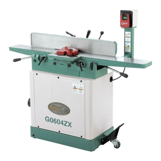
Parallelogram jointer
Hide thumbs
Also See for EXTREME Series:
- Owner's manual (92 pages) ,
- Manual insert (32 pages) ,
- Manual (10 pages)
Table of Contents
Advertisement
Quick Links
The following changes were recently made to these machines since the owner's manual was print-
ed:
owner's manual for future reference.
For questions or help, contact our Tech Support at (570) 546-9663 or techsupport@grizzly.com.
Changed Specifications
Electrical
Motor
Operation Info
WARNING: NO PORTION OF THIS MANUAL MAY BE REPRODUCED IN ANY SHAPE
OR FORM WITHOUT THE WRITTEN APPROVAL OF GRIZZLY INDUSTRIAL, INC.
READ THIS FIRST
Model G0604X/ZX
***IMPORTANT UPDATE***
For Machines Mfg. Since August, 2012
and Owner's Manual Printed June, 2006
IMPORTANT: Keep this update with the
Advertisement
Table of Contents

Related Manuals for Grizzly EXTREME Series


Summary of Contents for Grizzly EXTREME Series
- Page 1 The following changes were recently made to these machines since the owner's manual was print- IMPORTANT: Keep this update with the owner's manual for future reference. For questions or help, contact our Tech Support at (570) 546-9663 or techsupport@grizzly.com. Changed Specifications Electrical...
- Page 2 New/Revised G0604X Parts New/Revised G0604ZX Parts PART # DESCRIPTION P0604ZX140 POWER CORD 14G 3W 72" 5-15P P0604X228 MOTOR 1.5HP 120/240V 1-PH 228-1 P0604X228-1 FAN COVER 228-2 P0604X228-2 MOTOR FAN 228-3 P0604X228-3 CAPACITOR COVER 228-4 P0604X228-4 S CAPACITOR 300M 125V 228-5 P0604X228-5 R CAPACITOR 40M 250V 228-6...
- Page 3 SECTION 1: SAFETY For Your Own Safety, Read Instruction Manual Before Operating this Machine The purpose of safety symbols is to attract your attention to possible hazardous conditions. This manual uses a series of symbols and signal words intended to convey the level of impor- tance of the safety messages.
- Page 4 WEARING PROPER APPAREL. FORCING MACHINERY. NEVER STAND ON MACHINE. HAZARDOUS DUST. STABLE MACHINE. USE RECOMMENDED ACCESSORIES. HEARING PROTECTION. UNATTENDED OPERATION. REMOVE ADJUSTING TOOLS. MAINTAIN WITH CARE. INTENDED USAGE. CHECK DAMAGED PARTS. AWKWARD POSITIONS. MAINTAIN POWER CORDS. CHILDREN & BYSTANDERS. GUARDS & COVERS. EXPERIENCING DIFFICULTIES.
- Page 5 Additional Safety for Jointers JOINTER INJURY RISKS. INSPECTING STOCK. Main injury risks from jointers: GRAIN DIRECTION. KICKBACK. CUTTING LIMITATIONS. MAXIMUM CUTTING DEPTH PUSH BLOCKS. GUARD REMOVAL. WORKPIECE SUPPORT. DULL/DAMAGED KNIVES/INSERTS. FEED WORKPIECE PROPERLY. OUTFEED TABLE ALIGNMENT. SECURE KNIVES/INSERTS.
- Page 6 SECTION 2: POWER SUPPLY Availability Circuit Information For your own safety and protection of property, consult an electrician if you are Electrocution, fire, unsure about wiring practices or electrical equipment damage may codes in your area. occur if machine is not correctly grounded and Note: The circuit requirements listed in this man- connected to the power...
- Page 7 Grounding Requirements GROUNDED 6-15 RECEPTACLE 6-15 PLUG For 120V operation: Figure GROUNDED 5-15 RECEPTACLE 5-15 PLUG Figure Extension Cords SHOCK HAZARD! Two-prong outlets do not meet the grounding requirements for this machine. Do not modify or use an adapter on the plug provided—if it will not fit the outlet, have a qualified electrician install the proper outlet with a verified ground.
- Page 8 Voltage Conversion Figure IMPORTANT: If the diagram included on the motor conflicts with the one on the next page, the motor may have changed since the manual was printed. Use the diagram included on the motor junction box cover instead. Items Needed Figure 4.
- Page 9 G0604X/ZX 120V Wiring Diagram WARNING! SHOCK HAZARD! Disconnect power before working on wiring. 120 VAC MOTOR 5-15 Plug SWITCH (viewed from behind) G0604X/ZX 240V Wiring Diagram WARNING! SHOCK HAZARD! Disconnect power before working on wiring. MOTOR 240 VAC 6-15 Plug (As Recommended) SWITCH (viewed from behind)
- Page 10 ® Buy Direct and Save with Grizzly – Trusted, Proven and a Great Value! ~Since 1983~ Visit Our Website Today For Current Specials! ORDER 24 HOURS A DAY! 1-800-523-4777...
- Page 11 G0604X parts if you need to; otherwise, use the G0604 manual to order other parts. If you have any further questions about this manual insert or the differences between the Model G0604X and the Model G0604, contact our Technical Support at (570) 546-9663 or email techsupport@grizzly. com.
- Page 12 MACHINe dATA SHeeT Customer service #: (570) 546-9663 • to order Call: (800) 523-4777 • Fax #: (800) 438-5901 Model G0604X 6" eXTReMe SeRIeS JoINTeR design type: ....................Floor Model overall dimensions: table size ....................6" W x 55 ⁄...
- Page 13 G0604X 110V Wiring Diagram �������� ����� ������� ���������� ����� ������ ������� �� ������� ������� ��� ����� ��� ��� ��� ����� ��������� ��������� ������ ����� ������ ������ ������ � � � � � � � ������ � � ������� ���� ������� �...
- Page 14 6" X 56" JOINTER OWNER'S MANUAL COPYRIGHT © JUNE, 2006 BY GRIZZLY INDUSTRIAL, INC. WARNING: NO PORTION OF THIS MANUAL MAY BE REPRODUCED IN ANY SHAPE OR FORM WITHOUT THE WRITTEN APPROVAL OF GRIZZLY INDUSTRIAL, INC. #TR8349 PRINTED IN CHINA.
- Page 15 ���� ������ �������� �������� ������ ������������ �� ��� ������ ������ ���������� ����������� ��� ������� �� ���� ������������������ ������� �� ����� ���������� ��� ������ ��� ������������ ����� �� ���� ������ ��� ������ �� ������� �������� ������� ��������� ����������� ������������� �� ������ ���...
-
Page 16: Table Of Contents
Table of Contents INTRODUCTION ..........................3 Foreword ............................ 3 Contact Info ..........................3 Machine Data Sheet ........................4 Identification ..........................5 SECTION 1: SAFETY........................6 Safety Instructions for Machinery ....................6 Additional Safety for Jointers ..................... 8 SECTION 2: CIRCUIT REQUIREMENTS ..................9 110V Operation .......................... - Page 17 SECTION 7: SERVICE ........................31 Troubleshooting Guide ......................31 Inspecting Knives ........................33 Adjusting/Replacing Knives ...................... 33 Checking/Adjusting Table Parallelism ..................36 Setting Outfeed Table Height ....................38 Setting Infeed Table ......................... 39 Calibrating Depth Scale ......................40 Setting Fence Stops ......................... 40 Wiring Diagram ........................
-
Page 18: Introduction
E-Mail: techsupport@grizzly.com tinuous improvement, changes may be made at Web Site: http://www.grizzly.com any time with no obligation on the part of Grizzly. For your convenience, we always keep current Grizzly manuals available on our website at www. grizzly.com. Any updates to your machine will be reflected in these manuals as soon as they are complete. -
Page 19: Machine Data Sheet
Machine Data Sheet MACHINE DATA SHEET Customer Service #: (570) 546-9663 • To Order Call: (800) 523-4777 • Fax #: (800) 438-5901 MODEL G0604 6" X 56" Jointer Design Type: ....................Floor Model Overall Dimensions: Table Size ....................6" W x 55 ⁄... -
Page 20: Identification
Identification A. Outfeed Table B. Fence C. Fence Lock D. Fence Tilt Lock E. Cutterhead Guard Fence Tilt Handle G. Control Panel H. Infeed Table Infeed Table Adjustment Lever Mobile Base Lock K. Depth Scale Infeed Table Lock M. Outfeed Table Lock N. -
Page 21: Section 1: Safety
SECTION 1: SAFETY For Your Own Safety, Read Instruction Manual Before Operating this Machine The purpose of safety symbols is to attract your attention to possible hazardous conditions. This manual uses a series of symbols and signal words which are intended to convey the level of importance of the safety messages. - Page 22 Safety Instructions for Machinery 7. ONLY ALLOW TRAINED AND PROP- 17. REMOVE ADJUSTING KEYS ERLY SUPERVISED PERSONNEL TO WRENCHES. Make a habit of checking for OPERATE MACHINERY. Make sure keys and adjusting wrenches before turn- operation instructions are safe and clearly ing machinery ON.
-
Page 23: Additional Safety For Jointers
Additional Safety for Jointers JOINTER KICKBACK. "Kickback" is when KICKBACK ZONE. The "kickback zone" the workpiece is thrown off the jointer table is the path directly through the end of the by the force of the cutterhead. Always use infeed table. Never stand or allow others to push blocks and safety glasses to reduce stand in this area during operation. -
Page 24: Section 2: Circuit Requirements
SECTION 2: CIRCUIT REQUIREMENTS 110V Operation Grounding In the event of an electrical short, grounding reduces the risk of electric shock. This tool is equipped with a power cord that has a grounding wire, which must be properly connected to the grounding prong on the plug;... -
Page 25: Section 3: Setup
SECTION 3: SETUP Setup Safety Items Needed for Setup The following items are needed to complete the This machine presents setup process, but are not included with your serious injury hazards machine: to untrained users. Read through this entire manu- DESCRIPTION al to become familiar with •... -
Page 26: Inventory
Inventory After all the parts have been removed from the two boxes, you should have the following items: Jointer Box: (Figure 2) A. Jointer Assembly ........1 B. Carriage ............1 C. Fence ............1 D. Extension Table .......... 1 E. -
Page 27: Hardware Recognition Chart
Hardware Recognition Chart -12- G0604 6" X 56" Jointer... -
Page 28: Cleanup
Hex Bolt M8-1.25 x 50 ........1 solvent cleaner or citrus-based degreaser such Flat Washer 8mm ..........1 as Grizzly’s G7895 Degreaser. To clean thor- Hex Bolts M10-1.5 x 55 ........2 oughly, some parts may need to be removed. For Flat Washers 10mm .......... -
Page 29: Jointer
Jointer V-Belt Components and Hardware Needed: Components and Hardware Needed: Jointer Assembly ..........1 V-Belt ..............1 Stand Assembly w/Motor ........1 Belt Guard ............1 Cap Screws M8-1.25 x 25 ......... 4 Flange Bolts M6-1 x 12 ........2 Lock Washers 8mm ........... -
Page 30: Checking Outfeed Table Height
Checking Outfeed Table Height Cutterhead Pulley ��������� The outfeed table MUST be level with the knives when they are at top dead center (their highest point during rotation) or the workpiece cannot be fed across the jointer safely. Motor Pulley To check the outfeed table height: 1. -
Page 31: Extension Table
Extension Table When correctly set, the knife will barely touch the straightedge, as shown in Figure 11. —If your outfeed table is correctly set, no Components and Hardware Needed: adjustments are necessary. Extension Table ..........1 Cap Screws M6-1 x 20 ........2 —If the knife lifts the straightedge off the table or it is below the straightedge, then To install the extension table:... -
Page 32: Fence
Fence Components and Hardware Needed: Carriage ............. 1 Fence ..............1 Cap Screws M10-1.5 x 30 ......... 2 Flat Washers 10mm .......... 2 Cap Screws M8-1.25 x 30 ......... 2 To install the fence: Attach the fence carriage to the back of the table base (see Figure 13), but do not fully Figure 14. -
Page 33: Cutterhead Guard
Cutterhead Guard Pedestal Switch Components and Hardware Needed: Pedestal Switch ..........1 Cap Screws M8-1.25 x 20 ......... 2 The cutterhead guard is a critical safety fea- Lock Washers 8mm ........... 2 ture on this machine—you MUST install and Flat Washers 8mm ..........2 verify its operation before using the joint- er! Failure to install this guard will greatly To install the pedestal switch:... -
Page 34: Knife Setting Jig
Knife Setting Jig Dust Port Components and Hardware Needed: Components and Hardware Needed: Dust Port ............1 Knife Setting Jig Rod ......... 1 Phillips Screws M5-.8 x 16 ........ 4 Knife Setting Jig Foot ........2 Flat Washers 5mm ..........4 E-Clip .............. -
Page 35: Test Run
Test Run Recommended Adjustments For your convenience, the adjustments listed Loose hair and cloth- below have been performed at the factory and ing could get caught in no further setup is required to operate your machinery and cause machine. serious personal inju- ry. -
Page 36: Section 4: Operations
OMMEND that you read books, trade maga- zines, or get formal training before begin- Figure 22. Table control locations. ning any projects. Regardless of the con- tent in this section, Grizzly Industrial will not be held liable for accidents caused by lack of training. -21-... -
Page 37: Stock Inspection And Requirements
Stock Inspection Fence Movement: The fence has a lock that keeps it in position (Figure 23). To move the and Requirements fence, loosen the lock and slide the fence where needed. Here are some rules to follow when choos- ing and jointing stock: •... -
Page 38: Squaring Stock
Squaring Stock • Remove foreign objects from the stock. Make sure that any stock you process with the jointer is clean and free of any dirt, nails, staples, tiny rocks or any other foreign Squaring stock involves four steps performed objects that may damage the jointer blades. -
Page 39: Surface Planing
Surface Planing To surface plane on the jointer: Read and understand SECTION 1: SAFETY, beginning on Page 6. The purpose of surface planing on the jointer is to make one flat face on a piece of stock (see Make sure your stock has been inspected Figures 28 &... -
Page 40: Edge Jointing
Edge Jointing To edge joint on the jointer: Read and understand SECTION 1: SAFETY, beginning on Page 6. The purpose of edge jointing is to produce a fin- ished, flat-edged surface (see Figures 30 & 31) Make sure your stock has been inspected that is suitable for joinery or finishing. -
Page 41: Bevel Cutting
Bevel Cutting To bevel cut on the jointer: Read and understand SECTION 1: SAFETY, beginning on Page 6. The purpose of bevel cutting is to cut a specific angle into the edge of a workpiece (see Figures Make sure your stock has been inspected 32 &... -
Page 42: Section 5: Accessories
SECTION 5: ACCESSORIES G3640—Power Twist V-Belt - ⁄ " x 48" G1753—Jointer Pal Magnetic Knife Jig ® ® Smooth running with less vibration and noise (For HSS & Cobalt Knives) G1756—Jointer Pal Magnetic Knife Jig than solid belts. The Power Twist V-belt can be ®... - Page 43 G5562—SLIPIT 1 Qt. Gel H9221—6" HSS Replacement Jointer Knives ® G5563—SLIPIT 12 oz Spray (Set of 4) ® G2871—Boeshield T-9 12 oz Spray ® G2870—Boeshield T-9 4 oz Spray ® H1411—PowerHands Safety Stick ™ H3788—G96 Gun Treatment 12 oz Spray ®...
- Page 44 Features stainless steel, shock resistant construc- to wearing—at an affordable price! tion and a dust proof display. An absolute treat for the perfectionist! Figure 43. H6175 Power Respirator. Figure 45. Grizzly Dial Calipers. ® -29- G0604 6" X 56" Jointer...
-
Page 45: Section 6: Maintenance
SECTION 6: MAINTENANCE Cleaning Always disconnect power to the machine before Cleaning the Model G0604 is relatively easy. performing maintenance. Vacuum excess wood chips and sawdust, and Failure to do this may wipe off the remaining dust with a dry cloth. If any result in serious person- resin has built up, use a resin dissolving cleaner al injury. -
Page 46: Section 7: Service
SECTION 7: SERVICE Review the troubleshooting and procedures in this section to fix your machine if a problem develops. If you need replacement parts or you are unsure of your repair skills, then feel free to call our Technical Support at (570) 546-9663. - Page 47 Table Symptom Possible Cause Possible Solution 1. Table lock is engaged or partially 1. Completely loosen the table lock. Tables hard adjust. engaged. 2. Table stops blocking movement. 2. Loosen/reset table positive stops. Cutting Symptom Possible Cause Possible Solution Excessive snipe (gouge 1.
-
Page 48: Inspecting Knives
Inspecting Knives Adjusting/Replacing Knives The height of the knives can be inspected with a straightedge to ensure that they are set evenly Setting the knives correctly is crucial to the proper with the outfeed table at their highest point in the cutterhead rotation. - Page 49 Knife Setting Jig Method: Both tables are low- Tools Needed ered to fit the jig on the cutterhead, as shown in Straightedge ............1 Figure 47, and the knife heights are set to just Knife Setting Jig (Optional) ....... 1 touch the middle pad of the jig.
- Page 50 Remove and clean the gibs and clean inside Rotate the cutterhead to the first knife you the cutterhead slot to remove all pitch or saw- started with. Slightly tighten all the gib bolts, dust. Coat the knives and gibs with a metal starting in the middle and working your way to protectant (Page 28), then fit the gibs back in the ends by alternating left and right (Figure...
-
Page 51: Checking/Adjusting Table Parallelism
Checking/Adjusting Place the straightedge on the outfeed table so it hangs over the cutterhead, and lower Table Parallelism the outfeed table until the straightedge just touches the body of the cutterhead, as shown in Figure 52 (rotate the cutterhead if neces- sary). - Page 52 Checking Infeed Table Adjusting Table Parallelism To check the infeed table parallelism: For safe and proper cutting results, the tables must be parallel to the cutterhead. Adjusting them Follow all the steps for checking the outfeed to be parallel is a task of precision and patience, table parallelism to first make sure that the and may take up to one hour to complete.
-
Page 53: Setting Outfeed Table Height
Setting Outfeed Set Screw Eccentric Location Table Height Bushing The outfeed table height must be even with the top of the cutterhead knives. If the outfeed table is set too low, there will be snipe. If the outfeed table Figure 56. Eccentric bushing and set screw is set too high, the workpiece will hit the edge of location. -
Page 54: Setting Infeed Table
Setting Infeed Table Place the straightedge on the outfeed table so it hangs over the cutterhead, and lower the outfeed table until the straightedge is 0.062" ⁄ ") above the cutterhead body, as deter- The infeed table on the Model G0604 has mined by using the feeler gauge or combina- positive stop bolts that, when properly set up, tion of feeler gauges (see Figure 57). -
Page 55: Calibrating Depth Scale
Setting Fence Stops The fence stops simplify the task of adjusting the fence to 45˚ inward, 90˚, and 45˚ outward (135˚). Tools Needed 45° Square ............1 90° Square ............1 Sliding Bevel ............1 Wrench 10mm ........... 1 Hex Wrench 4mm ..........1 To set the 45˚... - Page 56 To set the 45° outward fence stop: To set the 90˚ fence stop: Loosen the fence tilt lock, and position the Loosen the set screw in the plunger lock fence against the 45° outward positive stop collar, shown in Figure 63, and loosen the bolt.
-
Page 57: Wiring Diagram
Wiring Diagram ����� ����� ���� ��������� ����� ���� ���� ��� ������� ���� ������� ����� ����� ������� ��� ��� ����� ��������� ������ ����� ������ ������ � � � � � � � � � � � ������ ������� ���� ������� �������� �... -
Page 58: Jointer Parts Breakdown
Jointer Parts Breakdown ��� ��� ��� �� ��� � �� ��� �� �� ��� � �� �� � ��� � � ��� �� ��� �� ��� �� �� � ��� � �� ��� ��� �� � ��� ��� � �� ��... -
Page 59: Jointer Parts List
Jointer Parts List PART # DESCRIPTION PART # DESCRIPTION P0604001 HANDLE PS68M PHLP HD SCR M6-1 X 10 P0604002 STUD PW03M FLAT WASHER 6MM P0604003 BUSHING P0604045 BALL HANDLE P0604004 SHAFT P0604046 STUD PSS11M SET SCREW M6-1 X 16 P0604047 FENCE PSS16M SET SCREW M8-1.25 X 10... - Page 60 Jointer Parts List PART # DESCRIPTION PART # DESCRIPTION P0604085 BUMPER P0604113 LEVER PW03M FLAT WASHER 6MM P0604114 HANDLE PSB07M CAP SCREW M6-1 X 30 PSB12M CAP SCREW M8-1.25 X 40 P0604088 BASE P0604116 CLAMP PLATE P0604089 RIVET P0604117 MEDIUM ADJUSTMENT SCR P0604090 SCALE P0604118...
-
Page 61: Stand/Motor Parts Breakdown
Stand/Motor Parts Breakdown ��� ��� ��� ��� ��� ��� ��� ����� ����� ����� ��� ����� ����� ��� ��� ��� ��� ��� ��� ��� ��� ��� ��� ��� ��� ��� ��� ��� ��� ��� ��� ��� ��� ��� ��� ��� ��� ���... -
Page 62: Stand/Motor Parts List
Stand/Motor Parts List PART # DESCRIPTION PART # DESCRIPTION PS40M PHLP HD SCR M5-.8 X 16 228-1 P0604228-1 FAN COVER PW02M FLAT WASHER 5MM 228-2 P0604228-2 MOTOR FAN P0604202 PANEL 228-3 P0604228-3 CAPACITOR COVER PFS02M FLANGE SCREW M6-1 X 12 228-4 P0604228-4 CAPACITOR 200MFD 125VAC... -
Page 63: Warning Label Parts List
MUST maintain the original location and readability of the labels on the machine. If any label is removed or becomes unreadable, REPLACE that label before using the machine again. Contact Grizzly at (800) 523-4777 or www.grizzly.com to order new labels. -48-... -
Page 64: Warranty And Returns
WARRANTY AND RETURNS Grizzly Industrial, Inc. warrants every product it sells for a period of 1 year to the original purchaser from the date of purchase. This warranty does not apply to defects due directly or indirectly to misuse, abuse, negligence, accidents, repairs or alterations or lack of maintenance. - Page 65 Would you recommend Grizzly Industrial to a friend? _____ Yes _____No Would you allow us to use your name as a reference for Grizzly customers in your area? Note: We never use names more than 3 times. _____ Yes _____No 10.
- Page 66 FOLD ALONG DOTTED LINE Place Stamp Here GRIZZLY INDUSTRIAL, INC. P.O. BOX 2069 BELLINGHAM, WA 98227-2069 FOLD ALONG DOTTED LINE Send a Grizzly Catalog to a friend: Name_______________________________ Street_______________________________ City______________State______Zip______ TAPE ALONG EDGES--PLEASE DO NOT STAPLE...
- Page 68 Buy Direct and Save with Grizzly – Trusted, Proven and a Great Value! ® Visit Our Website Today And Discover Why Grizzly Is The Industry Leader! ® • SECURE ORDERING • ORDERS SHIPPED WITHIN 24 HOURS • E-MAIL RESPONSE WITHIN ONE HOUR...
Need help?
Do you have a question about the EXTREME Series and is the answer not in the manual?
Questions and answers