Advertisement
Advertisement
Table of Contents

Related Manuals for Kospel SN series


Summary of Contents for Kospel SN series
- Page 1 Domestic Hot Water Cylinder Assembly and operating manual...
-
Page 2: Safety Instructions
Safety instructions 1. Read and strictly follow this installation and operating instructions to ensure a long life and reliable cylinder operation. 2. The cylinder’s installation and the initial start-up, as well as all electrical and hydraulic work must be performed by a qualified professional installer. 3. The device needs to be equipped with an additional safety valve (opening pressure 0,6MPa) in order to protect it from the excess pressure. - Page 3 Connection to the central heating system Cylinder must be fitted to the central heating system by pipe unions 1″. A cut-off valves must be installed before the pipe unions. A flow rate of heating water must be high enough to maximise cylinder’s efficiency (see ‘Technical data’ table). It concerns the forced circulation installation (with a central heating water pump). Model SN.P is equipped with a heating coil placed in the right part of the cylinder, whereas model SN.L in the left part of the cylinder. Heating coil enables co-operation with e.g. central heating boiler or solar collectors. SN.P SN.L GB-079_f.
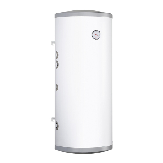
- Page 4 Connection to the water system Connection to the water system must be performed according to binding norms of hydraulic installation. The cylinder is a pressure appliance designed for connection to the water supply system where the water pressure doesn’t exceed 0,6 MPa. If the water pressure exceeds 0,6 MPa, the pressure reducing valve before cylinder must be fitted. Please follow the water connection instructions below: install the T-connection with 6 bar safety valve (e.g. ZB-4) and the drain valve to the fitting of cold water inlet [ZW]. It’s forbidden to install a cut-off valve (or any flow reducer) between tank and the safety valve and on its outlet. The safety valve must be installed in such a place as to quickly let you notice the outgoing water, install the cylinder equipped with the safety valve to the water system, install a cut-off valve on the cold water inlet. Hot water outlet should be led to the connection in the upper part of the cylinder. Every cylinder is equipped with connection 3/4″ intended for its installation to the DHW circulation. Cylinder’s construction [1] - anode’s blank Ø 460 [2] - magnesium anode [3] - thermal insulation [4] - hanger [5] - thermometer...
- Page 5 Start-up Before the start-up make sure that the installation procedures have been carried out in accordance with the regulations included in this manual. Cylinder must be filled with water: turn on the valve on cold water supply pipe, turn on the hot water outlet valve (water outflow without the air bubbles indicates that the tank is full), turn off the outlet valves. Turn on the heating medium and solar collectors valves. Check for water and heat- ing medium leaks. Check out the safety valve performance in accordance with valve manufacturer’s instruction. Operation Follow the guidelines below for safety and trouble-free cylinder operation: • Check out the safety valve performance once every 14 days. Do not use the cylinder if the water does not come out (it indicates that the valve is broken). • Clean inside of the cylinder periodically. The frequency of cleaning depends on the degree of water hardness. The cleaning should be done by a qualified person. • The wear condition of the anode must be inspected annually. • The anode must be replaced once every 18 months. anode rod replacement [2]: take off anode’s blank [1], take out an insulation ring, turn off the cut-off valve on cold water supply pipe, turn on the hot water valve (mixer tap), turn the drain valve on, drain as much water as you need to easily unscrew the anode rod (avoiding room flooding). Remove the cork and unscrew the anode rod. • Heat up the water above 70°C periodically for hygiene reasons. • Failures or malfunctions notify to the seller. • Insulate the outlet pipe and heating coil connection pipes to minimise the heat loss (recommended). Above activities are beyond of the scope of warranty service (should be done by the user).
-
Page 6: Technical Data
Technical data Domestic Hot Water Cylinder SN-80 SN-100 SN-120 Storage capacity storage Rated pressure coil Surface area of coil Capacity of coil Power of coil 7,5** *0,11 *0,14 *0,17 Heating time 20-60°C **0,34 **0,42 **0,50 Dimensions 978,4 1124,4 1294,4 Magnesium anode Weight (without water) heating water temp./ supply water temp./ domestic water temperature; flow rate *80/10/45°C of heating water through the coil - 2,5m **55/10/45°C... - Page 7 GB-079_f.
- Page 8 KOSPEL S.A. 75-136 Koszalin, ul. Olchowa 1 tel. +48 94 31 70 565 serwis@kospel.pl www.kospel.pl...
Need help?
Do you have a question about the SN series and is the answer not in the manual?
Questions and answers