Table of Contents
Advertisement
Advertisement
Table of Contents

Summary of Contents for eldoLED LINEARdrive
- Page 1 LINEARdrive Display User manual...
- Page 3 LINEARdrive Display User manual...
- Page 4 B.V. cannor be held liable for any direct or indirect loss or damage resulting from the use of the Information and/or resulting from the use of its products or material(s), except in the event of actions verging on eldoLED’s gross intent or intentional recklessness.
-
Page 5: Table Of Contents
2.4 Fastening the driver/controller to the surface............14 3 Connecting the driver/controller..................17 3.1 Required wire sizes....................17 3.1.1 LINEARdrive 180 ..................17 3.1.2 LINEARdrive 720 ..................18 3.2 Removing the strain reliefs ..................18 3.3 Connecting the leads ....................20 3.3.1 Locating the right connector ............... - Page 6 4.2.5 Configuring the operation mode ‘DMX’............36 4.2.6 Viewing the settings of operation mode ‘DALI’ ........... 37 4.2.7 Locking the configuration................38 4.2.8 Unlocking a soft-locked driver/controller............. 39 4.2.9 Carrying out a test run ................39 4.2.10 Resetting the driver/controller to its factory default settings ..... 40 A Specifications ........................
- Page 7 List of figures Figure 1.1: LINEARdrive ....................9 Figure 1.2: Creating your own show sequences with eldoLED PC software ....10 Figure 1.3: Clearly marked connectors on the LINEARdrive ........11 Figure 1.4: Strain reliefs on the LINEARdrive ............... 11 Figure 2.1: Removing the cover..................
- Page 8 Figure A.2: LINEARdrive’s mechanical dimensions............42 Figure A.3: Clearly marked connectors................. 43...
-
Page 9: Product Description
LINEARdrives can be integrated in a network or used as standalone devices. ShowMaster, supported on all eldoLED driver/controllers, allows you to upload show sequences for use in standalone mode. You can create and manage your own show sequences with the eldoLED TOOLbox and freely available PC software. -
Page 10: Showmaster
Visit www.eldoled.com/software to download the freely available PC soft- ware. Figure 1.2: Creating your own show sequences with eldoLED PC software 1.4 Low EMI LINEARdrive’s EMI is very low due to the implementation of slew-rate controlled dimming and shielded conductors. -
Page 11: Easy To Connect
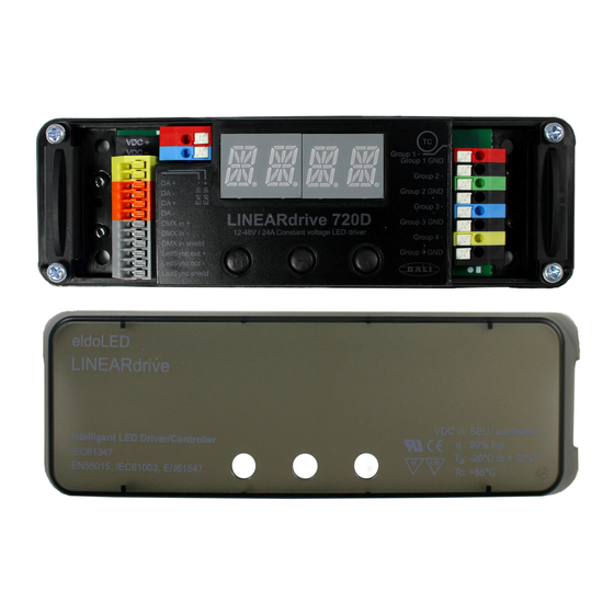
1.5 Easy to connect Connecting the LINEARdrive is self-explanatory: the spring-cage connectors for LEDs, power and network leads are all clearly marked. Figure 1.3: Clearly marked connectors on the LINEARdrive Strain reliefs prevent leads from being pulled out by accident. -
Page 13: Mounting The Driver/Controller
LINEARdrive 180 can be operated without a heat sink, as its own heat generation always stays within an acceptable temperature range. Being the most powerful of its range, LINEARdrive 720 must be mounted onto a heat sink. To ensure the best possible contact between the LINEARdrive 720 and the heat sink, LINEAR- drive 720 features a dual heat spreader. -
Page 14: Preparing The Mounting Surface
2.3 Preparing the mounting surface LINEARdrive can be mounted onto wood, plastic or metal. If you need to pre-drill mounting holes into the mounting surface or heat sink: 1. Remove the LINEARdrive’s cover as shown in 2.2 “Removing the cover”. -
Page 15: Figure 2.3: Fastening The Mounting Screws
It is recommended to mount eldoLED products in accordance with the IPC- A-620 standards. Figure 2.3: Fastening the mounting screws... -
Page 17: Connecting The Driver/Controller
The diameter of the wires including insulation material should be the same for all wires on the same side. The diameter of the wires including insulation material should be between 0.99mm and 3.12mm. 3.1.1 LINEARdrive 180 Wire core Insulation material to be... -
Page 18: Lineardrive 720
3.1.2 LINEARdrive 720 Wire core Insulation material to be Connector diameter in mm stripped away in mm 0.14 - 0.5 26 - 20 EXT in 0.14 - 0.5 24 - 20 DALI in 0.14 - 0.5 24 - 20 DALI out 0.14 - 0.5... -
Page 19: Figure 3.1: Removing The Strain Reliefs
Figure 3.1: Removing the strain reliefs... -
Page 20: Connecting The Leads
3.3 Connecting the leads This section first explains in general how to go about connecting a lead to the LINEARdrive, and then goes on to describe the specific springcage connectors. To connect the leads (power, network, LED, etc.): 1. Locate the correct connector for the lead that you wish to connect. The connectors are clearly marked on the base unit. -
Page 21: Locating The Right Connector
3.3.1 Locating the right connector The figures below show the wiring diagrams for the LINEARdrive Display 180 and 720 and are followed by a short explanation of the LINEARdrive’s springcage connectors. 12V-28V DC IN LED groups VDC - VDC +... -
Page 22: Connecting An External Input Device
3.3.1.2 Connecting an external input device It is possible to connect an external control device to the LINEARdrive. You can connect: Ω • a 10k potentiometer, allowing you to turn on/off and dim the light • a 0...10V control device, allowing you to turn on/off and dim the light •... -
Page 23: Connecting Led Groups
Connect the leads of your LED groups • to the LED supply and Group x connectors on the LINEARdrive 180’s right side • to the Group x and Group x GND connectors on the LINEARdrive 720’s right side LED sup... -
Page 24: Replacing The Strain Reliefs
3.4 Replacing the strain reliefs To replace the strain reliefs: 1. On both sides of the LINEARdrive, make sure the leads run between the strain reliefs’ screw holes. 2. Place the strain relief over the leads. 3. Fasten the strain reliefs’ screws. -
Page 25: Configuring The Driver/Controller
If you only need to change one setting, such as changing a colour or show sequence, you can leave the cover on and press the menu buttons using a pen. LINEARdrive SELV-equivalent Intelligent LED Driver/Controller... -
Page 26: General Function Of Menu Buttons
If the power is interrupted to a LINEARdrive that has already been configured, the display will only show the LINEARdrive type when the power comes back on, but will not go to the Set Mode menu, as the LINEARdrive’s configuration has been saved to memory. -
Page 27: Setting The Mode Of Operation
LINEARdrive 720. To enter the mode selection menu: 1. The very first time the power is connected to the LINEARdrive, the display will show the LINEARdrive type for a couple of seconds and then automatically enter the SET MODE menu. -
Page 28: Configuring Led Groups
After you have confirmed COLR MODE as the mode of operation, it is rec- ommended to set the LED groups via the SETUP menu first, before entering the COLR menu to set the colour of your choice. For information on how to configure the LED groups, see 4.2.2 “Configuring LED groups”... - Page 29 LED groups consisting of white LEDs only. 3. Press M to confirm the LED group configuration of your choice. 4. The EXT INP menu item allows you to configure the LINEARdrive for use with an ex- Ω...
-
Page 30: Configuring The Operation Mode 'Colr
4.2.3 Configuring the operation mode ‘COLR’ In COLR mode, you can set your LED application’s colour for standalone (i.e. non networked) operation. To change the COLR settings: 1. Press M to enter the COLR menu. Your options in the COLR menu depend on the way you have configured your LED groups in the SETUP menu. -
Page 31: Figure 4.6: Colr Settings For 3-3L
3-3L 3-3L: Three DMX channels are used for LED groups 1, 2 and 3. Group 4 is disabled. INT (intensity) lets you set the intensity of the light output of each channel: 255 is full on, 0 is off. Group 1 intensity INT 1 0...255 Group 2 intensity... -
Page 32: Figure 4.8: Colr Settings For Ccww Or Cwww
CCWW or CWWW CCWW: one DMX channel is used for two LED groups with the same colour and one DMX channel is used for two LED groups consisting of white LEDs only. CWWW: one DMX channel is used for one LED group and one DMX channel is used for three LED groups consisting of white LEDs only. -
Page 33: Figure 4.9: Setting The Colour
RGB / RRGB / RGGB RGB: 3 DMX channels are used for three LED groups: one channel for red LEDs, one for green LEDs and one for blue LEDs. RRGB: 3 DMX channels are used for four LED groups: two channels for red LEDs, one for green LEDs and one for blue LEDs. -
Page 34: Figure 4.11: Colr Settings For Rgbw Or Rgba
RGBW / RGBA RGBW: 4 DMX channels are used for four LED groups: one channel for red LEDs, one for green LEDs, one for blue LEDs and one for white LEDs. RGBA: 4 DMX channels are used for four LED groups: one channel for red LEDs, one for green LEDs, one for blue LEDs and one for amber LEDs. -
Page 35: Configuring The Operation Mode 'Show
Figure 4.13: Configuring show settings a. SHOW allows you to select a different show sequence. LINEARdrive can con- tain up to 20 show sequences. Show sequences can be uploaded to the driver/ controller at the factory, or with a TOOLbox and freely available PC software (downloadable at www.eldoled.com/software). -
Page 36: Configuring The Operation Mode 'Dmx
4.2.5 Configuring the operation mode ‘DMX’ In DMX MODE, you can set LINEARdrive’s network start address and its network resolution. DMX address DMX address ADDR ADDR 1...512 1...512 Network resolution Network resolution NETW NETW 8 BT 8 BT 16 BT... -
Page 37: Viewing The Settings Of Operation Mode 'Dali
In DALI MODE, you can view the DALI network settings that have been assigned to your LIN- EARdrive. To read out the LINEARdrive’s DALI settings: 1. Press M to enter the DALI menu. 2. Press M to browse the DALI network data:... -
Page 38: Locking The Configuration
4.2.7 Locking the configuration You can ensure that your driver/controller’s settings are not changed by locking its configura- tion. You can choose • not to lock the configuration: everyone with access to the driver/controller can change its settings. • soft-lock the configuration: you can only enter the SHOW, COLR or TEST menu or re- set the driver/controller to its factory defaults. -
Page 39: Unlocking A Soft-Locked Driver/Controller
4.2.8 Unlocking a soft-locked driver/controller To unlock a soft-locked driver/controller and regain full access to all menus: 1. Press M and + simultaneously for 5 seconds. 2. Press + or - until the display correctly reflects your choice: a. YES (the driver/controller remains soft-locked) b. -
Page 40: Resetting The Driver/Controller To Its Factory Default Settings
4.2.10 Resetting the driver/controller to its factory default settings To reset the driver/controller to its factory default settings: 1. Press M, - and + simultaneously for 5 seconds. 2. The display shows “RE-” “SET” and “PRES MENU” 3. Press M to carry out the reset, or do not press any button for 8 seconds - this allows you to exit the menu without actually carrying out the reset. -
Page 41: A Specifications
A Specifications Electrical data • Current: LINEARdrive 180: up to 6A (1.5A per channel) LINEARdrive 720: up to 24A (6A per channel) • Power output: LINEARdrive 180: up to 180 watts LINEARdrive 720: up to 720 watts • Operating supply voltage range: 12V-28V DC •... - Page 42 • Mounting holes: suited for M4 screws (4) Network control • Network input: USITT DMX512A, LedSync or DALI (DALI only on LINEARdrive 720) • Network output: LedSync, DALI (DALI only on LINEARdrive 720) • Network input/output: based on RS485 specification •...
- Page 43 • Cooling: passive (integrated heat spreader). Dual heat spreader on LINEARdrive 720 ensures ease of mounting onto required heat sink. • Required heat sink for LINEARdrive 720: heat sink must be able to dissipate 10% of the power consumed by the connected LED engine. For example, if the connected LEDs consume a total of 90W, the driver/controller requires a 9W heat sink.
- Page 44 Wire sizes LINEARdrive 180 • VDC: 0.14mm - 0.5mm (AWG 26 - 20) • EXT in: 0.5mm- 1.5mm (AWG 20 - 16) • DMX in: 0.5mm- 1.5mm (AWG 20 - 16) • LedSync thru: 0.5mm- 1.5mm (AWG 20 - 16) •...
- Page 46 LINEARdrive Display user manual V1.0...
Need help?
Do you have a question about the LINEARdrive and is the answer not in the manual?
Questions and answers