Table of Contents
Advertisement
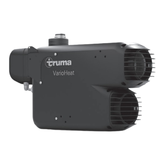
Truma VarioHeat comfort US
LP gas heater
Operating instructions
To be kept in the vehicle.
This document is part of the heater.
Conforms to ANSI Std. Z21.47
Certified to CSA Std. 2.3
4010007
FIRE OR EXPLOSION HAZARD
Failure to follow safety warnings exactly
could result in serious injury, death or prop-
erty damage.
Do not store or use gasoline or other flam-
mable vapors and liquids in the vicinity of
this or any other appliance.
WHAT TO DO IF YOU SMELL GAS
• Evacuate all persons from the vehicle.
• Shut off the gas supply at the gas contain-
er or source.
• Do not touch any electrical switch or use
any phone or radio in the vehicle.
• Do not start the vehicle's engine or electric
generator.
• Contact the nearest gas supplier or certi-
fied service technician for repairs.
• If you cannot reach a gas supplier or certi-
fied service technician, contact the nearest
fire department.
• Do not turn on the gas supply until gas
leaks have been repaired.
Installation and service must be performed
by a certified service technician, service
agency, or the gas supplier.
Advertisement
Table of Contents

Summary of Contents for Truma VarioHeat comfort US
- Page 1 Truma VarioHeat comfort US LP gas heater FIRE OR EXPLOSION HAZARD Operating instructions Failure to follow safety warnings exactly could result in serious injury, death or prop- To be kept in the vehicle. erty damage. This document is part of the heater.
-
Page 2: Table Of Contents
Safety symbols and signal words ........5 VarioHeat below. Safety behavior and practices ..........5 Safety features ..............7 Truma CP plus VarioHeat reffered to as CP plus Operating Instructions VarioHeat below. How the VarioHeat works ........... 7 Intended use Selectable modes of operation .......... -
Page 3: Mounting Arrangement / Accessories
Mounting arrangement / Accessories This is a typical installation for illustration. The installation in your vehicle may vary. The illustration is not to scale. Fig. 1 Legend A VarioHeat B CP plus VarioHeat C Room temperature sensor D Exhaust venting system E T-piece TS F End outlet EN G Wall outlet vent WL... -
Page 4: Varioheat Overview
VarioHeat Overview Fig. 2 Legend 1 Gas connection 2 Gas test pressure point 3 Switch for gas shut-off valve 4 Retainer 5 Exhaust venting system 6 Warm air outlet 7 Circulated air intake... -
Page 5: Consumer Safety Information
– Ensure that the VarioHeat cannot be • During the initial start-up of a brand new switched on through the Truma App un- appliance, small quantities of fumes and der any circumstances. a slight odor may occur briefly. When the appliance is started up after a particularly •... - Page 6 • Have a qualified service technician immedi- – Ventilation air can reach 250 °F (121 °C) at ately remedy any malfunctions. the warm air outlets. Always check the air temperature before varying the air throttle – Remedy a malfunction yourself only if a position (Fig. 1 –...
-
Page 7: Safety Features
Other functions can be selected with the digital control panel, such as a time switch or operation of a Truma AquaGo (refer to the Truma CP plus VarioHeat digital control panel operating instructions). The appliance always starts at the lowest set- ting. -
Page 8: Selectable Modes Of Operation
Check the VarioHeat for the following points before each use. In case of damage, contact an Off = gas shut-off valve is closed authorized Truma service provider and do not On = gas shut-off valve is open operate the VarioHeat. -
Page 9: Switching On The Varioheat
Truma CP plus VarioHeat control panel Switching on the VarioHeat The Truma CP plus VarioHeat digital con- For the heater to work properly, there must trol panel is described in separate operating be enough LP gas (propane >11 in. wc) and instructions. -
Page 10: Varioheat Technical Data
Temperature rise <134 °F (75 °C) Energy Input Rate / Gas Consumption LP gas mode Operating level 1 Operating level 2 Operating level 3 Truma VarioHeat 4700 BTU/h (1.4 kW) 8900 BTU/h (2.6 kW) 11500 BTU/h (3.4 kW) 3.5 oz/h (100 g/h) 6.7 oz/h (189 g/h) 8.6 oz/h (245 g/h) Power supply Power consumption at 12 VDC (DC <... -
Page 11: Varioheat" Manufacturer'slimited Warranty
/ or alterations of out- tute rental or for any other reason, even if Truma of-specification supplies, (ii) accidents, misuse, knew or should have known of the possibility of... -
Page 12: Maintenance And Service
• Always wear protective gloves to avoid injuries from sharp edges during mainte- nance work. There are no serviceable parts inside. In case of a defect please contact the Truma Service Center at 1-855-558-7862 or one of our authorized service partners to replace the complete VarioHeat. -
Page 13: Appendix
Appendix Warning labels The following pictures show the labels on the VarioHeat. If any of the labels are missing or unread- able, please contact the Truma Service Center on 1-855-558-7862. Fig. 33 Fig. 36 Fig. 34 Fig. 37 Fig. 35... - Page 16 In case you encounter any problems, please contact the Truma Service Center at 855-558-7862 or one of our authorized service partners. For details see www.truma.net. Please have the model number and serial number (on heater’s type plate) handy when you call.


Need help?
Do you have a question about the VarioHeat comfort US and is the answer not in the manual?
Questions and answers