Table of Contents
Advertisement
Quick Links
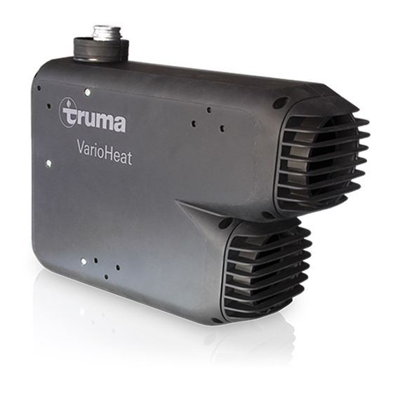
Truma VarioHeat comfort US
LP gas heater
Installation instructions
Conforms to ANSI Std. Z21.47
Certified to CSA Std. 2.3
4010007
FOR INSTALLER ONLY
To the consumer
Installing this Truma heater can be hazardous
due to LP gas and electrical components.
These installation instructions are only for use
by trained and qualified technicians.
To the installer
The operating instructions for this Truma
heater are part of these installation
instructions. The operating instructions
are included with the heater as a separate
document.
Advertisement
Table of Contents

Related Manuals for Truma VarioHeat comfort US


Summary of Contents for Truma VarioHeat comfort US
- Page 1 LP gas heater FOR INSTALLER ONLY Installation instructions To the consumer Installing this Truma heater can be hazardous due to LP gas and electrical components. These installation instructions are only for use Conforms to ANSI Std. Z21.47 Certified to CSA Std. 2.3 by trained and qualified technicians.
-
Page 2: Table Of Contents
Installer Safety Information ..........5 VarioHeat below. Safety symbols and signal words ........5 Safety behavior and practices ..........5 Truma CP plus VarioHeat referred to as CP plus Selecting an installation space ........... 6 VarioHeat below. Dimensions and clearance ........... 7 Dimensions ................ -
Page 3: Mounting Arrangement / Accessories
Mounting arrangement / Accessories This is a typical installation for illustration. The installation in your vehicle may vary. The illustration is not to scale. Fig. 1 Legend A VarioHeat B CP plus VarioHeat C Room temperature sensor D Exhaust venting system E T-piece TS F End outlet EN G Wall outlet vent WL... -
Page 4: Varioheat Overview
VarioHeat Overview Fig. 2 Legend 1 Gas connection 2 Gas test pressure point 3 Switch for gas shut-off valve 4 Retainer 5 Exhaust venting system 6 Warm air outlet 7 Circulated air intake... -
Page 5: Installation Instructions
“ VarioHeat Technical Data” in the operating instructions and the VarioHeat • Installation and service must be performed rating plate. by an authorized Truma-trained installer. Improper installation, alteration, service or • Use with LP gas (propane) only. Butane or maintenance can cause property damage, any mixtures containing more than 10 % of... -
Page 6: Selecting An Installation Space
Wood or PVC (Polyvinyl Chloride) floors / wall typically used in RVs can change color due to the temperature of the Var- ioHeat. Truma does not accept liability for this. Truma recommends removing the PVC in the area of the VarioHeat. -
Page 7: Dimensions And Clearance
VarioHeat and the exhaust tube. – This applies to items such as service hatch- es and cabinet doors. – Truma recommends a seating dinette, clos- et or under-bed location. • The VarioHeat must be mounted on a flat Fig. 3 surface. -
Page 8: Securing The Varioheat
Mounting • The floor / wall or false floor / wall must bracket bear the load of a secured VarioHeat. Contact the Truma Service Center on 1-855-558-7862 if you are unsure whether 1, 2 ... -
Page 9: Warm Air Distribution
The warm air is fed from the VarioHeat mainly to the floor area of the living room either directly or through flexible pipes (warm air distribution). Use only Truma accessories to distribute warm air in the RV. Various parts are available to ensure proper sup- ply of heated air from the heater (see Appendix C). - Page 10 A selection of Truma accessories for warm air Examples of warm air distribution with distribution. Truma accessories Warm air can be blown into the room directly Accessory Symbol Description from the VarioHeat. AD 80 Air duct AD 80, (Ø 80 mm)
-
Page 11: Installing The Air Duct Ad 80
Installing the air duct AD 80 Connecting the swivel air outlet SCW 2 with the VR 80 duct AD 80 Fig. 12 1. If a warm air distribution system is used, the grille on the warm air outlet of the heater must be removed. -
Page 12: Installing A T-Pipe Lt Or End Outlet En
3. Insert the UER 65 warm air duct into the EM end outlet nut until it fits snugly. Teeth AD 65 on the inside hold the duct in place.. For an even more secure fastening, Truma metal clips can be used (see Appendix C). AD 65 Circulated air intake Fig. -
Page 13: Exhaust Venting System
Roof Circulated air intake with grille If a grille (not included in the scope of delivery) is installed, the same requirements regarding the cross section 23 1/4 in.² (150 cm²) through which air flows must be observed. Floor VR 80 Side wall Fig. -
Page 14: Permissible Duct Lengths
Side wall Side wall Floor Fig. 21 With the VarioHeat, for installation with wall cowl, only the Truma exhaust duct AA 24 Intermediate (part no. 39420-00) and the combustion air floor min. infeed duct ZR 24 (part no. 39440-00) may be 12 in. -
Page 15: Making The Exhaust Venting System
Making the exhaust venting system Installing the wall cowl Exhaust and combustion air are conveyed by 1. Drill a hole with a diameter of 2 3/4 in. means of an exhaust venting system (tube in (70 mm); see Fig. 25. tube): an exhaust tube AA 24 (Fig. 24 – 1) and a combustion-air supply tube ZR 24 (Fig. -
Page 16: Connecting The Exhaust Venting System To The Varioheat
long enough and that are made of stainless steel. Fig. 28 Installing the outer part of the wall cowl Fig. 27 1. Use 2 screws (Fig. 26 – 13) (B 3.5 x 25) to fasten the outer part (Fig. 26 – 8) of the wall Installing the inner part of the wall cowl cowl in place. -
Page 17: Gas Connection
Gas connection Risk of explosion or poisoning due to damaged grommet and/or gas line! Connecting the gas line • Ensure sufficient length and flexibility of the gas line for a tension-free connection to Risk of explosion or poisoning due to the VarioHeat gas connection. -
Page 18: Checking For Gas Leaks
Installing the room temperature Checking for gas leaks sensor The room temperature sensor must Risk of death and personal injury through be connected, otherwise the VarioHeat will fire and/or explosion! malfunction. • DO NOT use matches, candles or other We recommend installing the room temperature sources of ignition when checking for gas sensor in the following way to maintain a steady leaks. -
Page 19: Electrical Connections
(105 °C), never attach or run connector – 2 x AWG 11 (2 x 4 mm²) up to 19 ft length cables near (8 m) – metal surfaces of equipment, – For lengths > 19 ft (8 m), contact Truma – aluminum frame feet, Service. – exhaust tubes, or – warm air ducts. -
Page 20: Connecting The Battery
Connecting the battery Depending on the cable cross section, crimp the 1/4 in. (6.3 mm) flat connectors included with the delivery on to the plus and minus ca- bles and plug into the plug X5 (if necessary, pro- tect the plus and minus cables; refer to “Setting up a 12-volt connection”... -
Page 21: Final Tasks
Final tasks A duplicate type plate with a removable bar code is included in the scope of supply. If the original type plate is not readily visible following installation of the VarioHeat, the du- plicate type plate must be affixed to a readily visible position on the VarioHeat. - Page 22 Appendix Appendix A - Warning labels The following pictures show the labels on the VarioHeat. If any of the labels are missing or unread- able, please contact the Truma Service Center on 1-855-558-7862. Fig. 41 Fig. 44 Fig. 42 Fig. 45 Fig.
-
Page 23: Appendix B - Combustion Air Quality
Appendix B - Combustion air quality Combustion Air Quality (List of Contaminants) There must be no exposure to substances listed below: • Permanent wave solutions • Chlorinated waxes and cleaners • Chlorine-based swimming pool chemicals • Water softening chemicals • De-icing salts or chemicals •... -
Page 24: Appendix C - Warm Air Accessories
Appendix C - Warm air accessories Optional accessories for optimum warm air installation in individual floor plans Product Part number Part number Description Purpose single pack bulk pack 40230-05 40230-51 Duct AD 80 US Warm air duct (3.3 ft. (1m)) (66 ft. - Page 25 Product Part number Part number Description Purpose single pack bulk pack 40721-10 40721-60 Lamellar insert LA, Lamellar insert LA (bulk 350 pieces) black for attachment to end outlet EN-O, 40721-11 40721-61 Lamellar insert LA, can be rotated to (bulk 350 pieces) white control the direc- tion of the air flow.
- Page 26 Product Part number Part number Description Purpose single pack bulk pack 40301-02 40301-52 Branch AB 35 To branch off a (bulk 60 pieces) warm air duct AD 35 from a warm air duct AD 65 40381-02 40381-52 Reducer RZ 35 To connect a duct (bulk 200 pieces) AD 35 to a duct AD 65...
-
Page 28: Appendix D - Spare Parts
Appendix D - Spare parts Exploded view of spare parts and accessories 12 V Fig. 47... - Page 29 VarioHeat US electrical parts kit 34030-28500 CP plus mounting frame 36110-03 Control panel cable 9 m 29.5 ft 39050-00565 Truma CP plus VarioHeat US spare part 34030-28600 Truma CP plus control knob 34030-28700 CP plus connector cable 50020-27800 Fuse holder incl. fuse 1 AF...
-
Page 30: Appendix E - Connection Diagram 12 Vdc
Appendix E - Connection diagram 12 VDC Fig. 48... - Page 32 In case you encounter any problems, please contact the Truma Service Center at 855-558-7862 or one of our authorized service partners. For details see www.truma.net. Please have the model number and serial number (on heater’s type plate) handy when you call.
Need help?
Do you have a question about the VarioHeat comfort US and is the answer not in the manual?
Questions and answers