Cisco NCS 4016 Installation Manual
Network convergence system ncs 4000 series
Hide thumbs
Also See for NCS 4016:
- Manual (24 pages) ,
- Unpacking and installing (8 pages) ,
- Hardware installation manual (82 pages)
Table of Contents
Advertisement
Quick Links
Advertisement
Table of Contents
Troubleshooting

Subscribe to Our Youtube Channel
Related Manuals for Cisco NCS 4016


Summary of Contents for Cisco NCS 4016
- Page 1 Cisco Network Convergence System 4000 Series Hardware Installation Guide November 2015 Cisco Systems, Inc. www.cisco.com Cisco has more than 200 offices worldwide. Addresses, phone numbers, and fax numbers are listed on the Cisco website at www.cisco.com/go/offices. Text Part Number:...
- Page 2 OR ITS SUPPLIERS HAVE BEEN ADVISED OF THE POSSIBILITY OF SUCH DAMAGES. Cisco and the Cisco logo are trademarks or registered trademarks of Cisco and/or its affiliates in the U.S. and other countries. To view a list of Cisco trademarks, go to this URL: www.cisco.com/go/trademarks.
-
Page 3: Table Of Contents
Cable Management Route Processor Cables Interface Cables Noise Control Cisco Installation Services System Testing, Certification, and Warranties Installing Power Components C H A P T E R Power Connection Guidelines AC-Powered Chassis Cisco Network Convergence System 4000 Series Hardware Installation Guide... - Page 4 Installing a Fabric Card 5-11 Installing a Fabric Card 5-11 Verifying the Installation of a Fabric Card 5-15 About Line Cards 5-16 2-Port 100Gbps and 10-Port 10Gbps OTN and Packet Line Card 5-16 Cisco Network Convergence System 4000 Series Hardware Installation Guide...
- Page 5 Replacing the External Connection Unit 6-28 Replacing an SSD 6-29 System Product IDs A P P E N D I X Component Product IDs Line Card Product IDs Cosmetic Product IDs Accessory Product IDs Cisco Network Convergence System 4000 Series Hardware Installation Guide...
- Page 6 Connecting Power to a DC-Powered Chassis 9-23 Disconnecting AC or DC Power 9-26 Disconnecting AC Power 9-26 Reconnecting AC Power 9-26 Disconnecting DC Power 9-27 Reconnecting DC Power 9-28 Powering On the Chassis 9-28 Cisco Network Convergence System 4000 Series Hardware Installation Guide...
- Page 7 Removing an RP Card 11-3 Removing a Fabric Card 11-5 Removing the Power Components 11-7 Removing AC Input Power Cords 11-7 Removing DC Input Power Cables 11-8 Removing a Power Module Slot Cover 11-9 Cisco Network Convergence System 4000 Series Hardware Installation Guide...
- Page 8 Line Card Product IDs Cosmetic Product IDs Accessory Product IDs System Specifications A P P E N D I X Chassis Specifications Power Specifications Environmental Specifications Regulatory, Compliance, and Safety Specifications Cisco Network Convergence System 4000 Series Hardware Installation Guide viii...
-
Page 9: Preface
This hardware installation guide describes how to install and remove a Cisco Network Convergence System (NCS) 4016 chassis and NCS 4009 chassis and its components. The Cisco NCS 4016 chassis and Cisco NCS 4009 chassis are converged optical service platforms in the Cisco NCS 4000 Series family. -
Page 10: Related Documentation
• Series Obtaining Documentation and Submitting a Service Request For information on obtaining documentation, using the Cisco Bug Search Tool (BST), submitting a service request, and gathering additional information, see What’s New in Cisco Product Documentation at: http://www.cisco.com/c/en/us/td/docs/general/whatsnew/whatsnew.html. Cisco Network Convergence System 4000 Series Hardware Installation Guide... - Page 11 Obtaining Documentation and Submitting a Service Request Subscribe to What’s New in Cisco Product Documentation, which lists all new and revised Cisco technical documentation as an RSS feed and delivers content directly to your desktop using a reader application. The RSS feeds are a free service.
- Page 12 Preface Obtaining Documentation and Submitting a Service Request Cisco Network Convergence System 4000 Series Hardware Installation Guide...
-
Page 13: Chapter 1 Installation Roadmap
Installation Roadmap Table 1-1 lists the steps to install the Cisco NCS 4016 chassis and its components and prepare the system for operation. Use this table as a checklist to ensure that all components are properly installed in the correct order. For information about a step, see the respective book or section of this installation guide. - Page 14 Chapter 1 Installation Roadmap Cisco Network Convergence System 4000 Series Hardware Installation Guide...
-
Page 15: Chapter 2 Chassis Overview
• Safety Guidelines, page 2-10 About the Cisco NCS 4016 Chassis The Cisco NCS 4016 chassis contains an upper card cage and a lower card cage, each with 11 cards (22 total). The following cards are supported: • 2 slots for route processor cards (RPs) 16 slots for line cards (LCs) •... -
Page 16: Chapter 2 Chassi Overview
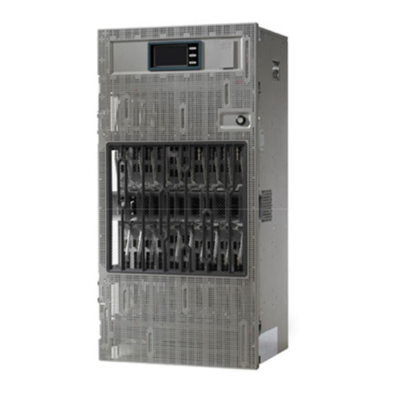
Chapter 2 Chassis Overview About the Cisco NCS 4016 Chassis Figure 2-1 shows the front view of the Cisco NCS 4016 chassis. Figure 2-1 Front View of the Cisco NCS 4016 Chassis Cisco Network Convergence System 4000 Series Hardware Installation Guide... - Page 17 Figure 2-4, and Figure 2-5 show partial rear views of the Cisco NCS 4016 chassis. There are two air outlets on the rear of the chassis. One is at the top behind the ECU and one is below Note the bottom fan tray.
- Page 18 Chapter 2 Chassis Overview About the Cisco NCS 4016 Chassis Figure 2-3 Rear View of the Cisco NCS 4016 AC Chassis Figure 2-4 Rear View of the Cisco NCS 4016 DC Chassis Cisco Network Convergence System 4000 Series Hardware Installation Guide...
-
Page 19: Chassis Components
Chapter 2 Chassis Overview Chassis Components Figure 2-5 Rear View of the Cisco NCS 4016 DC Chassis with DC Power Front Connection Adapter Chassis Components Table 2-1 lists the main components of the Cisco NCS 4016 chassis. Table 2-1 Main Components of the Cisco NCS 4016 Chassis... -
Page 20: Chassis Components
Description craft panel The craft panel can install, configure, monitor, and troubleshoot the Cisco NCS 4016 chassis applications at the node and at the network level. The craft panel is located on top of the ECU. fan trays Two fan trays are inserted into the front of the chassis at the top and bottom. -
Page 21: Chassis Slot Numbers
Cards in the top and bottom card cages are not inserted in the same direction. If you consider the top Note cards in Figure 2-6 as a reference, cards in the bottom card cage are inserted upside down. Cisco Network Convergence System 4000 Series Hardware Installation Guide... -
Page 22: Card Slot Requirements
The lower four power modules are contained within power tray 1 (PS1). They are named as follows: • PS1-PM0, PS1-PM1, PS1-PM2, and PS1-PM3. Card Slot Requirements Figure 2-7 shows card installation for the Cisco NCS 4016 chassis. Cisco Network Convergence System 4000 Series Hardware Installation Guide... - Page 23 FC3 are dedicated to fabric cards. Slots RP0 and RP1 are reserved for route processor cards. Shelf assembly slots have symbols indicating the type of cards that you can install in them. Each Cisco NCS 4016 card has a corresponding symbol. The symbol on the card must match the symbol on the slot. Table 2-2 shows the slot and card symbol definitions.
-
Page 24: Chassis Cable Management
Chassis Overview Chassis Cable Management Chassis Cable Management The Cisco NCS 4016 chassis has cable management features for the front side only. The horizontal cable management brackets are located above and below the card cages. Safety Guidelines Before you perform any Cisco NCS 4016 chassis installation procedures, review the safety guidelines in this section to avoid injuring yourself or damaging the equipment. -
Page 25: Preventing Electrostatic Discharge
ESD voltage on clothing can still cause damage. Figure 2-8 shows the ESD jacks on the top of the chassis. Figure 2-8 ESD Jacks—Top of Chassis 1 Top ETSI connection point 2 Top ANSI jacket point Cisco Network Convergence System 4000 Series Hardware Installation Guide 2-11... - Page 26 Safety Guidelines Figure 2-9 shows the ESD jacks on the bottom of the chassis. Figure 2-9 ESD Jacks—Bottom of Chassis 1 Bottom ANSI jacket point 2 Bottom ETSI connection point Cisco Network Convergence System 4000 Series Hardware Installation Guide 2-12...
-
Page 27: Basic Site And Installation Planning
Site Planning Considerations This chapter describes the general considerations to address while planning for the installation of the Cisco NCS 4016 chassis. As you plan for your system, keep in mind the specifications listed in Appendix B, “System Specifications.” This chapter includes the following sections: Basic Site and Installation Planning, page 3-1 •... -
Page 28: Equipment Rack Considerations
• Cable management for routing system cables • Equipment Rack Considerations A fully loaded Cisco NCS 4016 chassis weighs 412 lb (187 kg). The chassis is mounted in a two-post or a four-post rack. Figure 3-1 shows a four-post rack. -
Page 29: Aisle Spacing And Maintenance Access Floor Plan
Aisle Spacing and Maintenance Access Floor Plan The floor plan for the Cisco NCS 4016 chassis must include enough space to install the chassis in the equipment rack and allow sufficient airflow for the system. The floor plan must also provide enough room to access chassis components for maintenance (for example, to remove fan trays, power modules, cables, and air filters). -
Page 30: Front And Rear Clearances
As the size of the routing system increases, the cabling required for the chassis increases. For example, a fully loaded Cisco NCS 4016 chassis has more cables connected to it than a partially loaded chassis. The cabling runs must be carefully planned. The basic configurations for various routing systems should be arranged to minimize the complexity and length of the cable runs. -
Page 31: Interface Cables
• Noise Control The Cisco NCS 4016 chassis has some built-in noise reduction, such as fan speed control. If the routing system is installed in an environment where excessive noise could be harmful to personnel, some other noise reduction options could be attempted. Passive noise reduction could include the installation of foam panels to insulate the surrounding area from the noise. - Page 32 Chapter 3 Site Planning Considerations System Testing, Certification, and Warranties Cisco Network Convergence System 4000 Series Routers Site Planning Guide...
-
Page 33: Power Connection Guidelines
The power tray provides electrical connections to the chassis backplane. Each power module can be individually plugged in or out from the tray. Each Cisco NCS 4016 chassis is powered by only one type of input: AC or DC. A hybrid (AC+DC) power Caution configuration is not supported. -
Page 34: Ac-Powered Chassis
(NEC) and any local codes. For a list of the nominal and acceptable value ranges for source AC power, Table B-2. The Cisco NCS 4016 chassis supports two types of AC power cords: International and NEMA (USA). Figure 4-1 International AC Power Cord (Cisco PID NCS4K-AC-CBL-IEC) -
Page 35: Installing Power Components
The size of the cables depends on your chassis location from the source power. Follow your local practices for determining cable size. DC power cables are not available from Cisco, but they are available from any commercial cable vendor. - Page 36 No damage should occur from reverse polarity, but you should correct a reverse polarity condition immediately. For a list of the nominal and acceptable value ranges for source DC power, see Appendix B, “System Specifications.” Cisco Network Convergence System 4000 Series Hardware Installation Guide...
-
Page 37: General Power And Grounding Requirements
Site power planning must include the power requirements for any external terminals and test • equipment you will use with your system. Be sure to review the safety warnings in the Cisco Network Convergence System Regulatory Compliance Note and Safety Information for the Cisco Network Convergence System 4000 Series Routers before attempting to install the routing system. -
Page 38: Ac Power Requirements
Each AC power shelf contains four specific single phase AC inlet connectors. These connectors can accept four AC power cords provided by Cisco. AC power cords provided by Cisco can have a IEC-309 plug 32A rated for International power systems, or a NEMA L6-30P plug 30A rated for North America Power Systems. - Page 39 AC power modules. Figure 4-4 shows the NEBS bonding and grounding points on the NCS 4016 chassis. Figure 4-4 NEBS Bonding and Grounding Points on the Cisco NCS 4016 Chassis...
-
Page 40: Installing The Chassis Ground Cable
One grounding wire. Although we recommend at least 2-4-AWG multistrand copper wire, the wire diameter and length depend on your chassis location and site environment. Note These parts are not available from Cisco (with the exception of the grounding lug), but they are available from commercial vendors. Installing the Chassis Ground Cable This section describes how to install a ground cable to either NEBS bonding and grounding point on the front or side of the Cisco NCS 4016 chassis. -
Page 41: Installing The Chassis Ground Cable
To ensure a satisfactory ground connection, we recommend 2-4-AWG multistrand copper ground cable. This cable is not available from Cisco; it is available from any commercial cable vendor such as Panduit. The cable should be sized according to local and national installation requirements. - Page 42 1 NEBS grounding point on right side of the Screws chassis 3 Lock washers Use the torque wrench to tighten the bolts to a torque of 35 in-lb (3.95 N-m). Step 3 Cisco Network Convergence System 4000 Series Hardware Installation Guide 4-10...
-
Page 43: Installing An Ac Or Dc Power Tray
Step 4 requirements. Installing an AC or DC Power Tray The power tray is preinstalled on the Cisco NCS 4016 chassis. The following procedure describes how to install an AC or DC power tray in the chassis. Required Tools and Equipment 6-inch, number-1 Phillips screwdriver •... -
Page 44: Installing Power Modules
Forcing a module into the incorrect tray can cause damage to the module and the tray. Each power module has three status LEDs located on the front left side of its faceplate. Cisco Network Convergence System 4000 Series Hardware Installation Guide 4-12... -
Page 45: Installing Ac Or Dc Power Modules
Remove the filler caps from the slots where you want to install the power modules. Using two hands to support the power module, slide it into the power tray. Step 2 Cisco Network Convergence System 4000 Series Hardware Installation Guide 4-13... - Page 46 Chapter 4 Installing Power Components Installing Power Modules Figure 4-9 Example of Inserting the AC Power Module Secure the power module into the power tray using the snap hook. Step 3 Cisco Network Convergence System 4000 Series Hardware Installation Guide 4-14...
-
Page 47: Installing The Dc Power Front Connection Adapter
DC Power Front Connection Adapter. This DC adapter moves the DC power connections from the back of the chassis to the front of the chassis. This may be desirable in ETSI rack installations. Cisco Network Convergence System 4000 Series Hardware Installation Guide 4-15... - Page 48 If the rear to front power adapter is going to be used, then the sub assembly needs to be attached first to the chassis and then both units installed in a rack or cabinet. • The Cisco NCS 4016 chassis should be completely removed from the packaging and installed in the rack or cabinet. Required Tools and Equipment •...
- Page 49 Step 2 Attach the rear cable guide on top of the chassis toward the rear, and attach the insulator sheet on top of the chassis toward the front (Figure 4-13). Cisco Network Convergence System 4000 Series Hardware Installation Guide 4-17...
- Page 50 Attaching Rear Cable Guide and Insulator Sheet 2 Insulator sheet Rear cable guide Place the DC adapter on top of the chassis using the embossed references on the top chassis cover Step 3 (Figure 4-14). Cisco Network Convergence System 4000 Series Hardware Installation Guide 4-18...
- Page 51 Connect the power cables on the rear of the of DC adapter to the chassis terminal blocks (Figure 4-15). Step 4 Follow the connections scheme as shown on the labels available on the DC adapter and the chassis. Cisco Network Convergence System 4000 Series Hardware Installation Guide 4-19...
- Page 52 Installing the DC Power Front Connection Adapter Figure 4-15 Connecting Power Cables Connect power cables to chassis terminal blocks Install the rear cover to protect the cables (Figure 4-16). Step 5 Cisco Network Convergence System 4000 Series Hardware Installation Guide 4-20...
- Page 53 Installing the Rear Cover Install the chassis and DC adapter subassembly in the rack or cabinet. Attach the chassis brackets and Step 6 DC brackets to the rack (Figure 4-17). Cisco Network Convergence System 4000 Series Hardware Installation Guide 4-21...
- Page 54 Connect the power cables coming from batteries or from the PDU unit to the DC adapter terminal blocks Step 7 on the front side of the unit (Figure 4-18). See the “Connecting Power to the Chassis” section on page 4-23. Cisco Network Convergence System 4000 Series Hardware Installation Guide 4-22...
-
Page 55: Connecting Power To The Chassis
Follow these steps to connect the AC power cords to the chassis. Connect each AC power supply to a dedicated power source (branch circuit). Each AC input power Note supply operates at a nominal input level of 200 to 240 VAC. Cisco Network Convergence System 4000 Series Hardware Installation Guide 4-23... - Page 56 Typical AC Power Connections to an AC Power Tray Plug the other end of the AC power cord into the AC source receptacle. Step 6 Proceed to the “Powering On the Chassis” section on page 4-30. Step 7 Cisco Network Convergence System 4000 Series Hardware Installation Guide 4-24...
-
Page 57: Connecting Power To A Dc-Powered Chassis
To prevent injury and damage to the equipment, always attach the ground and source DC power cable Warning lugs to power tray terminals in the following order: (1) positive (+) to positive (+), (2) negative (–) to negative (–). Cisco Network Convergence System 4000 Series Hardware Installation Guide 4-25... - Page 58 DC Power Tray Rear Panel Figure 4-21 Typical Power Connections to a Power Tray for a Single DC Power Module—Power System Replace the clear plastic safety covers over the connection terminal studs. Step 6 Cisco Network Convergence System 4000 Series Hardware Installation Guide 4-26...
- Page 59 Chapter 4 Installing Power Components Connecting Power to the Chassis Figure 4-22 Typical Plastic Safety Covers over the Power Tray Connection Terminals Cisco Network Convergence System 4000 Series Hardware Installation Guide 4-27...
-
Page 60: Disconnecting Ac Or Dc Power
4-30. Step 7 Disconnecting AC or DC Power The following sections explain how to disconnect AC or DC power to the Cisco NCS 4016 chassis. Disconnecting AC Power Follow these steps to disconnect an individual AC power cord: Step 1 Power off (0) the circuit breaker assigned to the AC power source that you are disconnecting. -
Page 61: Disconnecting Dc Power
To prevent injury and damage to the equipment, always remove the source DC power cables from the Warning power tray terminals in the following order: (1) negative (–), (2) positive (+). Cisco Network Convergence System 4000 Series Hardware Installation Guide 4-29... -
Page 62: Reconnecting Dc Power
PWR MOD 3. Verify that the Power Output LED on each power module in the tray is lit. Step 4 Repeat Step 3 Step 4 for Feed B. Step 5 Cisco Network Convergence System 4000 Series Hardware Installation Guide 4-30... -
Page 63: About Installing Cards And Associated Components
Line Cards This chapter provides instructions on how to install route processor (RP) cards, fabric cards (FCs), line cards (LCs) and their associated components in the Cisco NCS 4016 chassis. • About Installing Cards and Associated Components, page 5-1 Installing and Removing a Filler Card, page 5-3 •... -
Page 64: Guidelines For Installing And Removing A Card
Note all other card slots. The different cards in the Cisco NCS 4016 chassis are all attached to the chassis itself using a pair • of ejector levers and captive screws. The two ejector levers release the card from its backplane connector. -
Page 65: Installing And Removing A Filler Card
Removing a Filler Card, page 5-5 Installing a Filler Card This section describes how to install a filler card in the Cisco NCS 4016 chassis. Prerequisites Before performing this task, open the front door, if installed, and ensure that the slot in which you are about to install the filler card is empty. -
Page 66: Removing A Filler Card
Phillips screwdriver or number-2 common [flat-head] screwdriver) to make sure that they are both engaged. Step 5 Use the number-2 Phillips screwdriver or number-2 common (flat-head) screwdriver to fully tighten the captive screws to seat the filler card firmly in the slot. Cisco Network Convergence System 4000 Series Hardware Installation Guide... -
Page 67: Removing A Filler Card
Installing Route Processor Cards, Fabric Cards, and Line Cards About RP Cards Removing a Filler Card This section describes how to remove a filler card from the Cisco NCS 4016 chassis. Prerequisites Before performing this task, open the front door, if installed. -
Page 68: Installing An Rp Card
Installing an RP Card Every Cisco NCS 4016 chassis contains two RP cards in dedicated slots on the right side of the chassis. The RP cards are identical. One RP card installs into slot RP0 on the top side of the chassis, and the second RP card installs into slot RP1 on the bottom side of the chassis. - Page 69 Installing Route Processor Cards, Fabric Cards, and Line Cards Installing an RP Card Figure 5-2 Installing an RP Card 1 Direction and location of insertion 3 Captive screws 2 Ejector levers 4 OIR buttons Cisco Network Convergence System 4000 Series Hardware Installation Guide...
- Page 70 Step 10 captive screws on the front panel of the card clockwise to seat the card firmly in the slot. Tighten the captive screws using 10.60 pound/force (lbf) inch (1.20 Nm torque). Cisco Network Convergence System 4000 Series Hardware Installation Guide...
-
Page 71: Verifying And Troubleshooting The Installation Of An Rp Card
Verifying and Troubleshooting the Installation of an RP Card This section describes how to verify that the RP card has been properly installed and how to troubleshoot the installation in the Cisco NCS 4016 chassis. Figure 5-3 shows the front panel of the RP card. -
Page 72: Troubleshooting The Rp Card
CLI command. If the installed or replaced card fails to operate or to power on after installation: Ensure that the card is seated firmly in the Cisco NCS 4016 chassis slot. One easy way to verify •... -
Page 73: About Fabric Cards
Lamp Test button—Push to enable a full test of all the LEDs on the chassis. About Fabric Cards The Cisco NCS 4016 chassis supports 4 fabric cards (FCs), which are agnostic cross-connects based on a flexible cell switching architecture used in a Clos configuration. FCs are called agnostic because they will switch a cell with no knowledge of whether they belong to OTN switching or Ethernet switching. -
Page 74: Installing A Fabric Card
Attach the ESD-preventive wrist strap to your wrist and connect its leash to one of the two ESD jacks located on the front or rear side of the chassis. You can also connect the ESD-preventive wrist strap leash to any bare metal surface on the chassis. Cisco Network Convergence System 4000 Series Hardware Installation Guide 5-12... -
Page 75: Verifying The Installation Of A Fabric Card
Attach the vertical cable management bracket to the faceplate of the FC using the two screws that came Step 12 with it. The dark gray arm should be facing up and the light gray arm should be facing down. See Figure 5-5. Cisco Network Convergence System 4000 Series Hardware Installation Guide 5-13... - Page 76 Chapter 5 Installing Route Processor Cards, Fabric Cards, and Line Cards Installing a Fabric Card Figure 5-5 Attaching the Vertical Cable Management Bracket Dark gray arm Light gray arm Cisco Network Convergence System 4000 Series Hardware Installation Guide 5-14...
-
Page 77: Verifying The Installation Of A Fabric Card
When the card status LED is off, verify that the card is installed correctly. There could be no power • applied to the card, a power fault, or a hardware fault. Cisco Network Convergence System 4000 Series Hardware Installation Guide 5-15... -
Page 78: About Line Cards
CLI command. If the installed or replaced FC fails to operate or power on after installation: Ensure that the card is seated firmly in the Cisco NCS 4016 chassis slot. One easy way to verify • physical installation is to see whether the front faceplate of the FC is even with the fronts of the other cards installed in the card cage. - Page 79 1 Port LEDs (one LED on each port) 2 CPAK 1 port 3 CPAK 0 port 4 Status LED 5 Attention LED 1. Port LEDs are triangular in shape and point toward the port that they support. Cisco Network Convergence System 4000 Series Hardware Installation Guide 5-17...
-
Page 80: Port Low-Rate Otn Line Card
ODU1, ODU0, and ODUFlex switching functions by interconnecting with the centralized agnostic switch fabric. Figure 5-8 shows the details of the front panel of the 24-port low-rate OTN LC and LEDs. Cisco Network Convergence System 4000 Series Hardware Installation Guide 5-18... - Page 81 24-Port Low-Rate OTN LC Descriptions State Description Status Green The LC is properly seated and operating correctly. Yellow The LC has one or more errors detected. No power is applied to the LC. Cisco Network Convergence System 4000 Series Hardware Installation Guide 5-19...
-
Page 82: Port 10Ge Otn Line Card
ODU4, ODU3, ODU2, ODU1, ODU0, and ODUFlex switching functions by interconnecting with the centralized agnostic switch fabric. The line card also supports direct interconnection to other slots within the Cisco NCS 4016 chassis to interconnect switched OTN traffic directly to the NCS 4000 2 x 100G CP-DQPSK - Full C band Tunable DWDM line card. - Page 83 20-Port 10GE OTN LC Descriptions State Description Status Green The LC is properly seated and operating correctly. Yellow The LC has one or more errors detected. No power is applied to the LC. Cisco Network Convergence System 4000 Series Hardware Installation Guide 5-21...
-
Page 84: Port 100Ge Otn Line Card
2-Port 100GE OTN Line Card The 2-port 100GE OTN LC (NCS4K-2H-O-K) supports any combination of 100GE and OTU4 interfaces using Cisco CPAK pluggable optics. Two CPAK receptacles are hosted on the faceplate. Insert CPAK modules in the 2-port 100GE OTN LC handle side down. - Page 85 The LC is properly seated and operating correctly. Yellow The LC has one or more errors detected. No power is applied to the LC. Attention Blue The card needs attention. The card does not need attention. Cisco Network Convergence System 4000 Series Hardware Installation Guide 5-23...
Need help?
Do you have a question about the NCS 4016 and is the answer not in the manual?
Questions and answers