
Subscribe to Our Youtube Channel
Related Manuals for Ametek JOFRA HPC600


Summary of Contents for Ametek JOFRA HPC600
- Page 1 User Manual Handheld Pressure Calibrator JOFRA HPC600 ©Copyright 2010 AMETEK Denmark A/S ...because calibration is a matter of confidence...
-
Page 2: Table Of Contents
JOFRA HPC600 Reference Manual 1. Introduction ...........1 1.1 Contacting AMETEK/JOFRA... -
Page 3: Jofra Hpc600
(measure/source), voltmeter and finally a high accuracy thermometer. The JOFRA HPC600 is designed to be a simple to use yet very versatile pressure calibrator. Its internal pressure sensor combined with an innovative... - Page 4 Symbol Description Double Insulated Electric Shock Fuse PE Ground Hot Surface (Burn Hazard) Read the User’s Manual (Important Information) Canadian Standards Association The following definitions apply to the terms “Warning” and “Caution”. • “Warning” identifies conditions and actions that may pose hazards to the user.
- Page 5 • Make sure the battery cover is closed and latched before you operate the calibrator. • Remove test leads from the calibrator before you open the battery door. • Inspect the test leads for damaged insulation or exposed metal. Check test leads continuity.
-
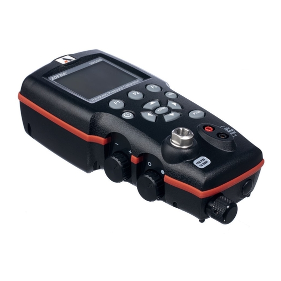
Page 6: Calibrator Interface
2. Calibrator Interface Figure 1 shows the location of the pressure controls, connection port and electrical inputs. Figure 1... - Page 7 Figures 2A and 2B show the location of the keys. Table 2 describes the function of each key. Figure 2A Keypad Table 2 Key Functions Name Description Function Keys These are soft keys used to configure the calibrator ON/OFF Key This key is used to turn the calibrator on and off ZERO Key This key is used to zero pressure measurements...
-
Page 8: Calibrator Display
2.1 Calibrator Display The Calibrator Display consists of two regions: The menu bar (located along the bottom of the screen) is used to access a menu system. The main display (the rest) consists of up to three process measurement sub-regions. These sub-regions will henceforth be referred to as the UPPER, MIDDLE and LOWER displays. - Page 9 2.1.2 Main Menu Functionality There are three options on the Menu, CONFIG, {Active Display} and MORE. The Main Menu is home for the menu display. 2.1.2.1 Setting the Active Display The active display is indicated by the center option on the Main Menu, pressing the F2 key will toggle the active display.
-
Page 10: Using The Backlight
The following table shows which functions are available concurrently. An X in a column indicates that the mode in the active display will not be available for selection if the mode in that row is in use in any other display. Table 4 Mode Concurrency CURRENT DISPLAY P[1]... -
Page 11: Other Menu Controlled Functions
2.3.2 Absolute Internal Sensor or Absolute Pressure Module When an absolute pressure sensor is selected on the current display and the ZERO KEY is pressed the calibrator displays the current barometric pressure on the lower display. At this point the user has two options. With the port open (vented) to atmosphere, and with access to a high accuracy barometric reference, the user can utilize the cursor keys to adjust the current value to the barometric reference pressure and store it in the calibrator using the SET... - Page 12 Menu Functions Overview 2.4.01 %ERROR, on line calculation of sensors error % ....Page 10 2.4.02 LEAK TEST, automatic leak test timer function ......Page 12 2.4.03 MINMAX, min / max hold ....……….………....Page 14 2.4.04 CONTRAST, display contrast adjustment ...……………... Page 15 2.4.05 LOCK CFG, instrument setup lock ......…….....
- Page 13 4. LOOP POWER can be toggled on/off, select NEXT when done. 5. Use SELECT to toggle through the UNIT options, and select NEXT to move on. 6. Use the cursor keys to set the 100% point of the desired pressure range, select DONE SET when finished.
- Page 14 7. Again, use the cursor keys to set 0% point and select DONE SET when finished and the %ERROR mode will be ready to use. Note: The 0% and 100% point will be saved in non-volatile memory until they are changed again by the user for the internal sensors and external pressure modules.
- Page 15 3. The first option is setting the Port, use the select option to scroll through the port choices, when finished select the NEXT option. 4. Use SELECT to toggle through the UNIT options, and select NEXT to move on. 5. Use cursor keys to set test time, and press DONE SET to confirm. Note: The units and time will be saved in non-volatile memory until they are changed again by the user.
- Page 16 EXIT leaves the leak rate function. 2.4.03 MIN MAX hold The JOFRA HPC600 Pressure Calibrators have a min/max feature for capturing the minimum and maximum values of any displayed parameter. To use the MIN / Max storage function proceed as follows: 1.
- Page 17 2.4.04 Setting the Display Contrast 1. With the calibrator turned on and operating press the F3 key to activate the MORE menu option. Press the NEXT button until CONTRAST appears in the left text field, now press the F1 key to activate the contrast adjustment function.
- Page 18 location. Then use the save option to store the current set-up into the selected location or the recall option to recall the set-up stored in the selected location. The display menu will automatically go home. 2.4.07 Setting AutoShut-off Parameters The calibrator can be set to automatically shut-off after a selected number of minutes;...
- Page 19 LOWER display will come on automat- ically. 2.4.09 Setting the RTD probe type The JOFRA HPC600 has a built in high accuracy RTD thermometer, it works with an RTD sensor (optional). To select type of temperature sensor proceed as follows: 1.
- Page 20 2. Switches the resistor on or off. 3. DONE returns to main menu. 2.4.12 Low resolution function. Due to the high accuracy of the JOFRA HPC600 the measured values are displayed with many digits, this might be an disadvantage in some cases,...
-
Page 21: Initial Setup And Basic Pressure Generation
3. Initial Setup and Basic Pressure Generation 1. The JOFRA HPC600 is supplied with a special low volume calibration hose kit to facilitate faster pumping to pressure and quick pressure stabilization. the kit also comes with the required “quick-fit” hose connectors and a BSP adapter for non-NPT applications. -
Page 22: Electric Pump Considerations
3.1 Electric Pump Considerations The JOFRA HPC600 a small, lightweight, battery powered pneumatic pump that allows the user up to 10 bar (150 psi) quickly and with good control. Because the pump has an upper pressure generation limit of 11 bar (160psi) there may be atmospheric conditions where it cannot achieve the full scale pressure of 10 bar. -
Page 23: Measuring Pressure
See section 2.3. 4.1 Media Compatibility The JOFRA HPC600 features a unique user accessible valve cleaning port to facilitate servicing the pump. Section 15.3 shows how to clean these valves. Even though servicing the pump is easy, care should be taken to only expose the calibrator to clean, dry gases. -
Page 24: Measuring And Generating Current
Figure 5 5. Measuring and Generating Current (4 to 20 mA) 1. To measure current use the input terminals in the front of the calibrator. Select the mA function on the lower display. Current is measured in mA and percentage of range. The range on the calibrator is set to 0% at 4 mA and 100% at 20 mA. - Page 25 5. While in the mA output mode if the loop is opened or the compliance is exceeded the unit will flash “OL ” . Figure 6-1 Figure 6-2 Figure 6-3...
-
Page 26: Measuring Voltage
Note: The factory default type is PT100-385 so if the HPC600 is being used with the AMETEK/JOFRA sensor you do not have to set the probe type. Simply plug the probe into the HPC600 and configure the display to read... -
Page 27: Performing A Pressure Switch Test
Note: The display will indicate "OL" when the measured temperature is outside the nominal measurement range of the RTD function (below -40°C or above 155°C). If a custom probe is being used, or adjustment of a standard probe is wanted, entering of CvD parameters, R0 and coefficients is handled through the serial interface, see remote programming manual. - Page 28 To perform a switch test, follow these steps: 1. Change the setup to Setup 4 (default switch test). Setup 4: The upper display is set to [P1] ST, all other displays are off. Important NOTE: The pressure Switch Test can be performed with the following functions[P1] ST, or EXT ST.
- Page 29 8. Press the “NEXT” option to view when the switch closed, and the dead band. 9. Press the “NEW TEST” option to clear the data and perform another test. 10. Press the “DONE” option to end the test and return to the standard pressure setting.
-
Page 30: Calibrating Transmitters
9. Calibrating Transmitters 9.1 Using the mA Input Function The mA input function allows the user to read back the 4-20 mA output from the device being calibrated. This can be done in one of two ways. 1) Passively – Where the device under test directly generates 4-20 mA and can be read by the calibrator. -
Page 31: Percent Error Function
Figure 10. 9.3 Percent Error Function The calibrator features a unique function which can calculate pressure vs. milliamp error as a percentage of the 4 to 20 mA loop span. The percent error mode uses all 3 screens and has a unique menu structure. It simultaneously displays pressure, mA and percent error. - Page 32 Example: Suppose a pressure transmitter under test is 30 psi (2 Bar) full scale and outputs a corresponding 4 to 20 mA signal. The user can program in a 0 to 30 psi pressure span into the calibrator and the calibrator will calculate and display the deviation or % Error from the expected 4 to 20 mA output.
- Page 33 6. Use the arrow keys to set the 100% point of the desired pressure range, select DONE SET when finished. 7. Again, use the arrows to set 0% point and select DONE SET when finished and the %ERROR mode will be ready to use. Note: The 0% and 100% point will be saved in non-volatile memory until they are changed again by the user for the internal sensors, and external pressure modules.
-
Page 34: Minimum And Maximum Storage Capability
10. Minimum and Maximum Storage Capability The HPC600 has a min/max feature for capturing the minimum and maximum values of any displayed parameter. The min/max function can be accessed by stepping through the menu options until “min/max” is shown on the display above the F1 key. At this time, pressing the F1 key will toggle the display through the min/max values that are stored in the min/max registers. - Page 35 1. With the calibrator turned on and operating press the F3 key to activate the MORE menu option. Press the NEXT button until LEAK TEST appears in the left text field. Now press the F1 key to activate the leak test option. 2.
-
Page 36: Factory Setups
6. To start leak test press F1 button, the time is counted down, and the Initial, Final and calculated leak rate in pressure pr. Minute is shown. EXIT leaves the leak rate function. 12. Factory Setups The Calibrator is loaded with five factory commonly used setups. These setups are shown below. - Page 37 Setup 3: The upper display is set to [P1] mode and the middle is set to RTD, lower is mA. Setup 4: The lower display is set to [P1] switch test, the other displays are off. Setup 5: The upper display is set to [P1], the middle display is set to [EXT] and the lower display is set to RTD.
-
Page 38: Custody Transfer / Flow Calibration
13. Custody Transfer / Flow Calibration The Model HPC600 is ideal for flow computer calibration. Every manufacturer of flow computers has a different calibration procedure, but most call for calibration of three parameters: static pressure, differential pressure and temperature. To facilitate these measurements recall setup #5 on the HPC600. -
Page 39: Specifications
15. Specifications (15 °C to 35 °C unless otherwise noted.) General Instrument Setup Recall 5; last used on power-up Environmental Operating Temperature -10 °C to +50 °C (14 to 122 ºF) Storage Temperature -20 °C to +60 °C (4 to 140 ºF) Power Requirements 12 VDC Battery... -
Page 40: Maintenance
16.3 Valve Cleaning Procedure Occasionally, the JOFRA HPC600 may not work properly due to dirt or other contamination of the internal valve assembly. Use the following procedure for cleaning the valve assembly. If this procedure does not fix the problem, a... -
Page 41: Service Center Calibration Or Repair
repair kit (part number 1010043) may be ordered. 1. Using a small screwdriver, remove the 2 valve retention caps located in the battery compartment area (see Figure 1, page 4). 2. After the caps have been removed, gently remove the spring and o-ring assembly. - Page 42 Appendix X...
- Page 44 AMETEK JOFRA™ HPC600 Ranges and Resolutions Range (PSI) 2.0 Bar / 30 PSI 10 Bar / 150 PSI Burst Pressure (PSI) Proof Pressure (PSI) Engineering Unit Factor 30.000 150.00 0.06894757 2.0684 10.3421 mbar 68.94757 2068.4 10342.1 6.894757 206.84 1034.21 .00689476 0.2068...
- Page 48 AMETEK GmbH (Germany) Tel: +49 2159 9136 510 • info.mct-de@ametek.de Information in this document is subject to change without notice. AMETEK Calibration Instruments (UK) ©2009, by AMETEK, Inc., www.ametek.com. All rights reserved. Tel: +44 (0) 1243 833 302 • jofra@ametek.co.uk...
Need help?
Do you have a question about the JOFRA HPC600 and is the answer not in the manual?
Questions and answers