Table of Contents
Advertisement
Advertisement
Table of Contents

Subscribe to Our Youtube Channel
Related Manuals for Emotron VSB Series


Summary of Contents for Emotron VSB Series
- Page 1 Emotron VSB AC Drive 0.4kW to 3.7kW / 0.54Hp to 5Hp Instruction manual English...
- Page 3 Thank you for choosing E m o tro n V S B S eries G en eral P u rp o se AC M o to r D rives from CG Drives & Automation. This user manual presents a detailed description of Emotron VSB series with respect to product features, structural characteristics, functions, installation, parameter setting, troubleshooting, commissioning and daily maintenance, etc.
-
Page 5: Table Of Contents
C O N T E N T S C h ap ter 1 S afety P reca u tio n s ........... - 1 - 1.1 Safety Considerations ....................- 1 - 1.2 Other Considerations ....................- 6 - C h ap ter 2 P ro d u ct Inform atio n ..........- 9 - 2.1 Model Explanation .................... -
Page 6: Table Of Contents
4.2 Potentiometer Setting .................... - 39 - 4.3 Prompt Message Status ..................- 39 - 4.4 Parameter Setting ....................- 40 - 4.5 Initial Power up ..................... - 41 - C h ap ter 5 L ist of P aram eters ..........- 47 - C h ap ter 6 S p ecificatio n o f P aram eters ........ -
Page 7: Safety Considerations
Emotron VSB Instruction Manual Chapter 1 Safety Precautions C h ap te r 1 S afety P reca u tio n s S a fe ty P re c a u tio n s Safety signs in this manual: W A R N IN G... - Page 8 Emotron VSB Instruction Manual Chapter 1 Safety Precautions 1 .1 .2 In s ta lla tio n W A R N IN G Only qualified personnel familiar with adjustable frequency AC drives and associated machinery should plan or implement the installation. Failure to comply may result in equipment damage and/or personnel injury even death.
- Page 9 Emotron VSB Instruction Manual Chapter 1 Safety Precautions 1 .1 .3 W iring W A R N IN G Only qualified personnel familiar with adjustable frequency AC drives and associated machinery should plan or implement the wiring. Failure to comply may result in personnel injury and/or equipment damage.
- Page 10 Emotron VSB Instruction Manual Chapter 1 Safety Precautions AT T E N T IO N Since all adjustable frequency AC drives from CG Drives & Automation have been subjected to hi-pot test before delivery, users are prohibited from implementing such a test on this equipment.
- Page 11 Emotron VSB Instruction Manual Chapter 1 Safety Precautions AT T E N T IO N Make sure the number of phases of power supply and rated voltage are consistent with product nameplate. If not, contact the seller or CG Drives & Automation.
-
Page 12: Other Considerations
Emotron VSB Instruction Manual Chapter 1 Safety Precautions 1.2 O th er C o n sid eration s 1 .2 .1 In p u t P ow e r S up p ly This series of drives are not applicable to applications out the range of operating voltage as set forth in this manual. - Page 13 Emotron VSB Instruction Manual Chapter 1 Safety Precautions period of time. The motor in regular service should also be subjected to regular insulation inspection so as to avoid the drive damage as a result of motor insulation damage. 1 .2 .6 D e ra tin g...
- Page 14 Emotron VSB Instruction Manual Chapter 1 Safety Precautions - 8 -...
-
Page 15: Chapter 2 Product Information
Emotron VSB Instruction Manual Chapter 2 Product Information C h ap te r 2 P ro d u ct In fo rm atio n 2.1 M o d el E xp lan atio n Model shown on product nameplate indicates the series name, applicable type of power supply, power class and hardware, etc. - Page 16 Emotron VSB Instruction Manual Chapter 2 Product Information 2 .3 In fo rm a tio n o f P ro d uc t M o d e l Tab le 2-1 P rod u ct m o d el and tech n ical d ata E m o to n V S B 23...
- Page 17 Emotron VSB Instruction Manual Chapter 2 Product Information 2 .4 Te c hn ic a l F e a tu re s o f E m o tro n V S B Ta b le 2 -3 Te c h n ic a l Fe a tu res o f E m o tro n V S B...
- Page 18 Emotron VSB Instruction Manual Chapter 2 Product Information Start frequency 0.00 - 600.00Hz Accel/Decel 0.00 - 60000s time Carrier 0.7kHz - 12kHz Digital setting + keypad ∧ / ∨ frequency Digital setting + terminal UP/DOWN Basic Frequency Potentiometer setting sources...
- Page 19 Emotron VSB Instruction Manual Chapter 2 Product Information various master & auxiliary commands and their switch, a variety of Accel/Decel curves optional, analog auto correction, 8-step speed Featured programmable, three faults history, over excitation brake, over voltage stall protection, under voltage stall protection, restart upon power loss, skip...
-
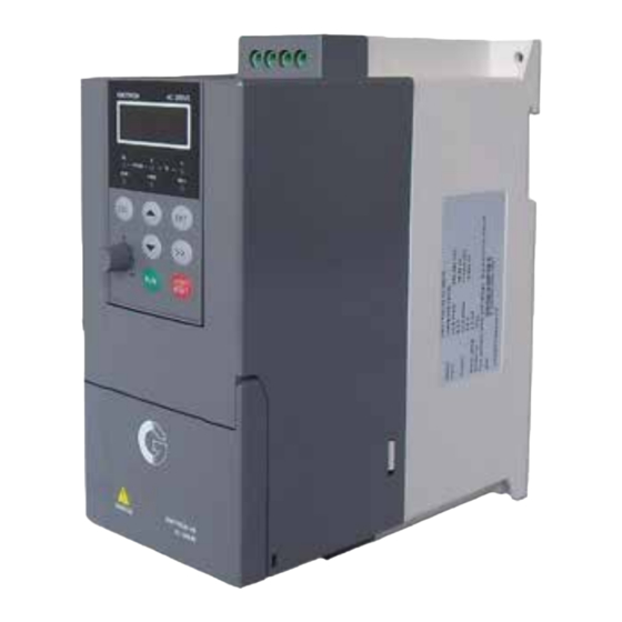
Page 20: Parts Drawing
Emotron VSB Instruction Manual Chapter 2 Product Information 2.5 P arts D raw in g Mounting holes DIN-rail groove Keypad Nameplate Cover Middle casing Fig. 2-3 Parts explanation 2.6 Ap p earan ce, M o u ntin g D im en sio n s an d W eig h t Fig. - Page 21 Emotron VSB Instruction Manual Chapter 2 Product Information Ta b le 2 -4 A p p e a ra nc e , m o u ntin g d im e n s ion s an d w e ig h t fo r...
-
Page 22: External Dimensions Of Keypad
Chapter 2 Product Information 2.7 E xtern al D im en sio ns o f K e yp ad Keypad model of general purpose Emotron VSB series AC motor drive is KBU-BX2 whose appearance and external dimensions are shown in Fig. 2-5. -
Page 23: Installation Environment
To ensure favorable heat dissipation, mount the drive upright on a flat, vertical and level surface as per Fig. 3.1. Emotron VSB series can be wall-mounted or DIN-rail mounted. When installation is performed inside cabinet, the product shall be mounted side by side to the greatest extent while adequate surrounding space shall be preserved for favorable heat dissipation. -
Page 24: Remove & Mount Keypad And Cover
Emotron VSB Instruction Manual Chapter 3 Installation and wiring AT T E N T IO N : If a number of drives are mounted in one cabinet, parallel side-by-side mounting is recommended 3.3 R em o ve & M o u n t K e yp ad an d C o ver 3 .3 .1 R em o ve a n d M o u n t K eyp a d... - Page 25 Emotron VSB Instruction Manual Chapter 3 Installation and wiring 3 .3 .2 O p en & C lo se C o ve r O p en th e co ver Pull out as indicated by “1” in Fig. 3-4 a) with thumb.
-
Page 26: Selection Of Peripheral Devices
Emotron VSB Instruction Manual Chapter 3 Installation and wiring 3.4 S electio n of P erip heral D evices Ta b le 3 -1 S e lec tio n o f p e rip he ra l d e vic e s... -
Page 27: Terminal Configuration
Emotron VSB Instruction Manual Chapter 3 Installation and wiring 3.5 Term in al C o nfig u ratio n Grounding terminal Main circuit input terminals Control circuit terminals Main circuit Grounding terminal output terminals Fig. 3-5 Terminal configuration. - 21 -... -
Page 28: Main Circuit Terminals And Wiring
Emotron VSB Instruction Manual Chapter 3 Installation and wiring 3.6 M ain C ircuit Term inals an d W irin g W A R N IN G Only qualified personnel familiar with AC motor drives are allowed to implement wiring. - Page 29 Emotron VSB Instruction Manual Chapter 3 Installation and wiring 3 .6 .1 M a in C irc u it Te rm in a ls Fig. 3-6 Main circuit terminals Terminal marks Designation and function of terminals Uniphase/Triphase AC power supply input (connect L1/L, L1/L、L2、L3/N...
-
Page 30: Control Terminal Wiring
Emotron VSB Instruction Manual Chapter 3 Installation and wiring 3.7 C o n tro l Term in al W irin g W A R N IN G Only qualified personnel familiar with AC motor drives are allowed to implement wiring. - Page 31 Emotron VSB Instruction Manual Chapter 3 Installation and wiring 3 .7 .2 W iring D ia g ram Fig. 3-7 Wiring diagram. - 25 -...
-
Page 32: Control Terminal Specification
Emotron VSB Instruction Manual Chapter 3 Installation and wiring 3.8 C o n tro l Term in al S pecificatio n Ta b le 3 -3 C o n tro l te rm in a l sp e c ifica tio n... -
Page 33: Control Terminal Usage
Emotron VSB Instruction Manual Chapter 3 Installation and wiring Category Terminal Terminal Specification designation 485 communication Isolated from COM interiorly shield grounding Maximum communication distance is 5m Keypad Keypad interface when connected to Keypad interface communication Use GTAKE dedicated cable shield grounding 3.9 C o n tro l Term in al U sag e... - Page 34 Emotron VSB Instruction Manual Chapter 3 Installation and wiring lines (e.g. power lines, motor lines, relay lines and contactor lines) and should not be arranged in parallel with strong current lines. In case it is inevitable to intersect strong current line, vertical wiring is recommended to avoid drive faults as a result of noise.
- Page 35 Emotron VSB Instruction Manual Chapter 3 Installation and wiring Fig. 3-10 X terminal low activated O p en collecto r External Controller +24V Jumper Drive +24V Opto Opto Shielded Cable Near-end Grounded Fig. 3-11 Open collector PNP wiring A T T E N T IO N : When selecting OC PNP wiring, dip switch should be switched to H terminal.
- Page 36 Emotron VSB Instruction Manual Chapter 3 Installation and wiring +24V Jumper External Controller Drive Opto Opto Shielded Cable Near-end Grounded Fig. 3-12 Open collector PNP wiring A T T E N T IO N : When selecting OC NPN wiring, dip switch should be switched to L terminal.
- Page 37 Emotron VSB Instruction Manual Chapter 3 Installation and wiring In stru ctio n s o f d ig ital o u tpu t term in al In stru ctio n s o f Y ou tp u t term inal...
- Page 38 Emotron VSB Instruction Manual Chapter 3 Installation and wiring 3 .1 0 In s tru c tion o f S ig n a l S w itc h e s Fig. 3-15 Jumper diagram of signal switching Default Designation Function setting I: current input (0 - 20mA);...
- Page 39 Emotron VSB Instruction Manual Chapter 3 Installation and wiring Disconnect the grounding connection of equipment may avoid this misoperation and/or faults Sensitive equipment and signal lines shall be mounted as far away from drive as possible. Signal lines should be provided with shielded layer and reliably grounded. Alternatively, ...
- Page 40 Emotron VSB Instruction Manual Chapter 3 Installation and wiring the carrier frequency. Leakage current is classified into ground leakage current and line-to-line leakage current. Ground leakage current not only circulates inside drive system, but may also influence other equipment via ground loop. Such a leakage current may result in malfunction of RCD and other equipment.
-
Page 42: Chapter 4 Operation And Run Instruction
Emotron VSB Instruction Manual Chapter 4 Operation and Run instructions C h ap te r 4 O p e ra tio n an d R u n In structio n s 4.1 O p eratio n o f K e yp a d As a human-machine interface, keypad is the main part for the drive to receive command and display parameters. - Page 43 Emotron VSB Instruction Manual Chapter 4 Operation and Run instructions 4 .1 .1 K e y F u n c tio n s o n K e yp a d On keypad there are 7 keys and 1 knob whose functions are as shown in Table 4-1.
- Page 44 Emotron VSB Instruction Manual Chapter 4 Operation and Run instructions 4 .1 .2 K e yp a d In d ic a to rs Keypad is furnished with 6 indicators whose descriptions are as stated below T a b le 4 -2 D e sc rip tio n o f in dic a to rs...
-
Page 45: Potentiometer Setting
Emotron VSB Instruction Manual Chapter 4 Operation and Run instructions 4.2 P o tentiom eter S ettin g Potentiometer could be frequency setting source or process PID setting programmed by related parameters. When b0-01 is set to 3, potentiometer is source of master frequency command. -
Page 46: Parameter Setting
4 .4 .1 P a ram e te r S ys te m Emotron VSB series drive parameter group: A0, b0~b2, C0~C4, d0~d2, E0~E1, F0~F1, H0, L0~L1, U0~U1. Each parameter group contains a number of parameters. Parameter codes are identified by the combination "parameter group character + parameter subgroup number + parameter number". -
Page 47: Initial Power Up
Emotron VSB Instruction Manual Chapter 4 Operation and Run instructions 4.5 In itial P ow er u p Perform wiring in strict accordance with technical requirements as set forth in Chapter 3 - Installation and Wiring. 4 .5 .1 E x a m ple s fo r Q u ic k se tu p The following are examples for Quick setup with wiring and parameter settings. - Page 48 Emotron VSB Instruction Manual Chapter 4 Operation and Run instructions A p p lic a tio n p a ram e te r se tting s a s b e low . Tab le 4-4 Parameter Designation Set Value Comment...
- Page 49 Emotron VSB Instruction Manual Chapter 4 Operation and Run instructions 4 .5 .1 .2 A n a lo g ue s pe e d re fe re n c e 4 -2 0 m A to A I 1. Set Signal switch A0 to I, see chapter 3.10 Instruction of Signal Switches.
- Page 50 Emotron VSB Instruction Manual Chapter 4 Operation and Run instructions A p p lic a tio n p a ram e te r se tting s a s b e low . Tab le 4-5 Parameter Designation Set Value Comment...
- Page 51 Emotron VSB Instruction Manual Chapter 4 Operation and Run instructions 4 .5 .1 .3 4 p res e t sp e e ds a nd S ta rt/S to p b y D ig ita l In p u ts 1.
- Page 52 Emotron VSB Instruction Manual Chapter 4 Operation and Run instructions A p p lic a tio n p a ram e te r se tting s a s b e low . Tab le 4-6 Parameter Designation Set Value Comment...
-
Page 53: Chapter 5 List Of Parameter
Emotron VSB Instruction Manual Chapter 5 List of Parameters C h ap te r 5 Lis t o f P aram eters Emotron VS parameter groups are listed below: Category Parameter group Related pages Group A: system parameter A0: system parameters P- 48 -;... - Page 54 Emotron VSB Instruction Manual Chapter 5 List of Parameters A T T E N T IO N : C h an g e attribu te: "△ " means the value of this parameter can be modified in stop and running status of drive;...
- Page 55 Emotron VSB Instruction Manual Chapter 5 List of Parameters Factory Param Designation Range Attr default 0: Digital setting (b0-02) + adjustment on keypad 1: Digital setting (b0-02) + terminal UP/DOWN adjustment b0-01 Master frequency command source 2: Analog input AI ×...
- Page 56 Emotron VSB Instruction Manual Chapter 5 List of Parameters Factory Param Designation Range Attr default b0-15 Lower limit of skip frequency band 2 0.00Hz~upper limit frequency 0.00Hz × b0-16 Upper limit of skip frequency band 2 0.00Hz~upper limit frequency 0.00Hz ×...
- Page 57 Emotron VSB Instruction Manual Chapter 5 List of Parameters Factory Param Designation Range Attr default b1-10 Flying start current 0.0% - 200.0% 100% △ B1-11 Flying start time 0.1s – 20.0s 2.0s △ 0: Ramp to stop b1-13 Stop method 1: Coast to stop ×...
- Page 58 Emotron VSB Instruction Manual Chapter 5 List of Parameters Factory Param Designation Range Attr default broken-line Accel/Decel △ Time of first segment of Accel b2-15 0.00s~60.00s 0.20s S-curve △ Time of last segment of Accel b2-16 0.00s~60.00s 0.20s S-curve △...
- Page 59 Emotron VSB Instruction Manual Chapter 5 List of Parameters Factory Param Designation Range Attr default terminal control 29: Run command switched to communication control 30: Frequency command pattern shift 31: Master frequency command switched to digital setting b0-02 32: Auxiliary frequency command...
- Page 60 Emotron VSB Instruction Manual Chapter 5 List of Parameters Factory Param Designation Range Attr default 1: run direction can be changed △ Terminal UP/DOWN frequency C0-18 0.00Hz/s~100.00Hz/s 0.10 Hz/s adjustment step size 0: Two-wire mode 1 1: Two-wire mode 2 C0-19 FWD/REV terminal control mode ×...
- Page 61 Emotron VSB Instruction Manual Chapter 5 List of Parameters Factory Param Designation Range Attr default 26: Accumulative running time △ attained △ C1-04 Y output time delay 0.0s~3600.0s 0.0s C1-06 Relay output time delay 0.0s~3600.0s 0.0s Unit's place: Y 0: Positive logic...
- Page 62 Emotron VSB Instruction Manual Chapter 5 List of Parameters Factory Param Designation Range Attr default Corresponding set value of curve 2 C2-06 100.0% × Range: -100.0%~100.0% maximum input Curve 2 inflection point B input ~ C2-07 Curve 2 inflection point A input 0.0%...
- Page 63 Emotron VSB Instruction Manual Chapter 5 List of Parameters Factory Param Designation Range Attr default Sampling value of AI calibration C4-01 1.00V ■ Range: 0.00V~10.00V point 1 C4-02 Input value of AI calibration point 1 Range: 0.00V~10.00V 1.00V × Sampling value of AI calibration C4-03 9.00V...
- Page 64 Emotron VSB Instruction Manual Chapter 5 List of Parameters Factory Param Designation Range Attr default defined Model d0-13 Motor flux weakening coeff 2 0.0000~1.0000 × defined Model d0-14 Motor flux weakening coeff 3 0.0000~1.0000 × defined 0: No autotune d0-22 Motor parameter autotune 1: Static autotune ×...
- Page 65 Emotron VSB Instruction Manual Chapter 5 List of Parameters Factory Param Designation Range Attr △ default d1-17 V/f oscillation suppression gain 2 0~3000 Group d2 Motor Vector Control Parameters △ ASR high-speed proportional gain d2-01 0.0~20.0 △ d2-02 ASR high-speed integration time Ti1 0.000s~8.000s 0.500...
- Page 66 Emotron VSB Instruction Manual Chapter 5 List of Parameters Factory Param Designation Range Attr default 2: Seven-segment mode Hundreds place: over-modulation adjustment 0: Disabled 1: Enabled Unit's place: selection when consecutive running time attained: 0: Continue to run 1: Stop and fault alarm...
- Page 67 Emotron VSB Instruction Manual Chapter 5 List of Parameters Factory Param Designation Range Attr default Hundreds place: reserved Thousands place: abnormal terminal communication: 0: Protection enabled and coast stop 1: Continue to run Unit's place: reserved Decad: current detection circuit failed...
- Page 68 Emotron VSB Instruction Manual Chapter 5 List of Parameters Factory Param Designation Range Attr default 1: Opposite direction allowed Decade: integration selection 0: Integral continued when frequency attains upper/lower frequency 1: Integral stopped when frequency attains upper/lower limit PID positive and negative...
- Page 69 Emotron VSB Instruction Manual Chapter 5 List of Parameters Factory Param Designation Range Attr default UP/DOWN adjustment 3: AI 7: Process PID output 8: Communication 0: Digital setting F1-03 1: Digital setting b0-04 + keypad ∧/∨ adjustment Frequency command source of...
- Page 70 Emotron VSB Instruction Manual Chapter 5 List of Parameters Factory Param Designation Range Attr default 5: 1-7-1-O format, ASCII Hundreds place: connection type 0: Direct cable connection (232/485) 1: MODEM (232) Thousands place: storage 0: Not stored at power loss...
- Page 71 Emotron VSB Instruction Manual Chapter 5 List of Parameters Factory Param Designation Range Attr default Unit's place: selection on stop 0: Clear on stop 1: Holding on stop Decade: selection on power loss 0: Clear on power loss 1: Holding on power loss L0-03 ∧/∨...
- Page 72 Emotron VSB Instruction Manual Chapter 5 List of Parameters Factory Param Designation Range Attr default be displayed as default Setting of binary system: 0: Display disabled 1: Display enabled Unit's place: BIT0: Command frequency (Hz) BIT1: Bus voltage (V) BIT2: Input terminal status...
- Page 73 Emotron VSB Instruction Manual Chapter 5 List of Parameters Factory Param Designation Range Attr default Unit's place: run status 0: Accelerating 1: Decelerating 2: Constant speed running U0-11 Drive status ■ Decade: drive status 0: Stop 1: Run status 2: Autotuning U0-12 AI input voltage 0.00V~10.00V...
- Page 74 Emotron VSB Instruction Manual Chapter 5 List of Parameters Factory Param Designation Range Attr default 6: Decel overvoltage 7: Module protection 8: Autotuning failed 9: Drive overloaded 10: Motor overloaded 11: Current detection abnormal 12: Ground short-circuit protection at output side...
- Page 75 Emotron VSB Instruction Manual Chapter 5 List of Parameters Factory Param Designation Range Attr default U1-18 Fault 3 code Same as U1-00 ■ U1-19 Fault 3 run frequency 0.00Hz~600.00Hz 0.00Hz ■ U1-20 Fault 3 output current 0.0A~6553.5A 0.0A ■ U1-21 Fault 3 bus voltage 0V~1000V ■...
-
Page 76: Group A System Parameter And Parameter Management
Emotron VSB Instruction Manual Chapter 6 Specification of Parameters C h ap te r 6 S p ecificatio n o f P aram eters G ro u p A S ystem P aram eter an d P aram eter M an ag em en t... -
Page 77: Group B Setting Of Running Parameters
Emotron VSB Instruction Manual Chapter 6 Specification of Parameters difficult to identify motor parameters correctly, etc. When motor under V/f control is selected, need to set related parameters group d1 well. 1: Sensor-less vector control 1 This helps achieve high-performance control without encoder and provides strong adaptability of load. - Page 78 Emotron VSB Instruction Manual Chapter 6 Specification of Parameters - 72 -...
- Page 79 Emotron VSB Instruction Manual Chapter 6 Specification of Parameters Frequency command Factory default: b0-00 Range: 0 - 4 pattern 0: Master frequency command Output frequency of drive is determined by master frequency command source b0-01. Refer to parameters b0-01 and b0-02 for further information.
- Page 80 Emotron VSB Instruction Manual Chapter 6 Specification of Parameters Frequency adjustment via ∧ / ∨ on keypad can be cleared through terminal "UP/DOWN (including AT T E N T IO N : ∧ / ∨ key) adjustment clear " . Refer to C0-01 - C0-08 for details.
- Page 81 Emotron VSB Instruction Manual Chapter 6 Specification of Parameters 8: Multi-step speed A total of 8-step speed settings can be realized through status combination of "multi-step frequency terminal 1 - 3". See the table below for details. Command frequency can be switched via different combination of multi-step frequency terminals no matter in running or in stop.
- Page 82 Emotron VSB Instruction Manual Chapter 6 Specification of Parameters 0: No command Auxiliary frequency command is disabled, and auxiliary frequency is 0. 1: Digital setting (b0-04) + ∧ / ∨ adjustm ent on keypad be adjusted through ∧ / ∨ on keypad no matter the drive is running or in stop status.
- Page 83 Emotron VSB Instruction Manual Chapter 6 Specification of Parameters 10: Communication Upper computer is the auxiliary frequency command source of the drive through standard RS485 communication interface on the drive. Refer to Group H0 and appendix on this manual for further information about communication protocol, and programming, etc.
- Page 84 Emotron VSB Instruction Manual Chapter 6 Specification of Parameters E xam ple: Select AI as auxiliary frequency command source (set b0-03 to 3) and set AI to curve 1 (unit's place of C2-00 is 0) as shown in Fig. 6-5. In such a case, the frequency that corresponds to the maximum input of curve 1 should be: (C2-02) ×...
- Page 85 Emotron VSB Instruction Manual Chapter 6 Specification of Parameters E xam ple: When selecting AI as auxiliary frequency command source (set b0-03 to 3) and setting AI to curve 1 (unit's place of C2-00 is 0), the frequency that corresponds to maximum input of curve 1 should be: (C2-02) ×...
- Page 86 Emotron VSB Instruction Manual Chapter 6 Specification of Parameters Range: Upper limit frequency - Factory default: b0-08 Maximum frequency 600.00Hz 50.00Hz Range: Lower limit frequency - Factory default: b0-09 Upper limit frequency maximum frequency 50.00Hz Range: 0.00Hz - upper limit...
- Page 87 Emotron VSB Instruction Manual Chapter 6 Specification of Parameters Operation when command frequency b0-11 Range: 0 - 2 Factory default: 0 lower than lower limit frequency 0: Run at lower limit frequency In case command frequency is lower than lower limit frequency, the running should be at lower limit frequency.
- Page 88 Emotron VSB Instruction Manual Chapter 6 Specification of Parameters Frequency after adjustment 调节后的频率 b0-18 Skip frequency band 3 跳跃频率3 b0-17 b0-16 Skip frequency band 2 跳跃频率2 b0-15 b0-14 Skip frequency band 1 跳跃频率1 b0-13 Command frequency 设定频率 Fig. 6-7 Once parameters of skip zones are set, the output frequency of the drive would automatically get out of these skip zones even if the command frequency is within these zones.
- Page 89 Emotron VSB Instruction Manual Chapter 6 Specification of Parameters AT T E N T IO N : Output frequency of drive can normally pass through skip zones during Accel and Decel. Range: 0.00Hz - upper limit Factory default: b0-19...
- Page 90 Emotron VSB Instruction Manual Chapter 6 Specification of Parameters G ro u p b 1 S ta rt/S to p C o n tro l b1-00 Run command Range: 0 - 2 Factory default: 0 This parameter sets run command source. Run commands include "start, stop, forward and reverse", etc.
- Page 91 Emotron VSB Instruction Manual Chapter 6 Specification of Parameters Unit's place: frequency command source bundled under keypad control 1: Digital setting (b0-02) + ∧ / ∨ adjustment on keypad 0: No binding 2: Digital setting (b0-02) + terminal UP/DOWN adjustment...
- Page 92 Emotron VSB Instruction Manual Chapter 6 Specification of Parameters Output frequency 输出频率 Time 时间 Fig. 6-9 Dead time between forward and reverse b1-05 Start method Range: 0 - 3 Factory default: 0 This parameter takes effect during the process of transition from stop status to running status.
- Page 93 Emotron VSB Instruction Manual Chapter 6 Specification of Parameters holding time is disabled during transition between forward and reverse. Accel time of Group b2 excludes holding time of start frequency. DC braking current Factory default: b1-08 Range: 0.0% - 100.0% when start 0.0%...
- Page 94 Emotron VSB Instruction Manual Chapter 6 Specification of Parameters Factory default: b1-15 DC brake current Range: 0.0% - 100.0% 0.0% Factory default: b1-16 DC brake time Range: 0.00s - 30.00s 0.00s During the process “ramp to stop + DC braking", DC brake would be started when output frequency attains set value of b1-14.
- Page 95 Emotron VSB Instruction Manual Chapter 6 Specification of Parameters Auto restart when power up b1-20 Range: 0 - 1 Factory default: 0 again after power loss Defines the drive status when power up again after power loss during running 0: Disabled The drive will not run automatically when power is up after power loss.
- Page 96 Emotron VSB Instruction Manual Chapter 6 Specification of Parameters Factory default: b2-06 Decel time 3 Range: 0s - 60000s 6.0s Factory default: b2-07 Accel time 4 Range: 0s - 60000s 6.0s Factory default: b2-08 Decel time 4 Range: 0s - 60000s 6.0s...
- Page 97 Emotron VSB Instruction Manual Chapter 6 Specification of Parameters Factory default: b2-10 Jog Accel time Range: 0s - 60000s 6.0s Factory default: b2-11 Jog Decel time Range: 0s - 60000s 6.0s b2-10 and b2-11 set the rate of Accel/Decel of Jog, similar with b2-01 - b2-08.
- Page 98 Emotron VSB Instruction Manual Chapter 6 Specification of Parameters A T T E N T IO N : When broken-line Accel/Decel is enabled, " Accel/Decel time determinant 1" and " Accel/Decel time determinant 2" will be disabled. Broken-line Accel/Decel is as shown in Fig. 6-11.
- Page 99 Emotron VSB Instruction Manual Chapter 6 Specification of Parameters if this parameter value is selected. Ac tu al Accel tim e = lin ear Accel tim e + (Tim e o f in itial seg m en t of Accel S -cu rve...
- Page 100 Emotron VSB Instruction Manual Chapter 6 Specification of Parameters Time of initial segment of b2-15 Range: 0.00s - 60.00s Factory default: 0.20s Accel S-curve Time of last segment of b2-16 Range: 0.00s - 60.00s Factory default: 0.20s Accel S-curve Time of initial segment of b2-17 Range: 0.00s - 60.00s...
-
Page 101: Group C Input And Output Terminals
Emotron VSB Instruction Manual Chapter 6 Specification of Parameters G ro u p C In p ut an d O u tp u t Term in als G ro u p C 0 D ig ita l In p u t... - Page 102 Emotron VSB Instruction Manual Chapter 6 Specification of Parameters Ta b le 6 -2 Multi-step Multi-step Multi-step frequency frequency frequency Command frequency terminal 3 terminal 2 terminal 1 Multi-step frequency 0 (F1-00) Multi-step frequency 1 (F1-01) Multi-step frequency 2 (F1-04)
- Page 103 Emotron VSB Instruction Manual Chapter 6 Specification of Parameters AT T E N T IO N : Terminal delay time and C0-11 filtering time can be used at the same time. X1 and X2 terminal signals first go through filtering time, then through delay time set by C0-12 and C0-13.
- Page 104 Emotron VSB Instruction Manual Chapter 6 Specification of Parameters 1: Holding Terminal UP/DOWN frequency adjustment value is maintained when the drive stops. Decade: action on power loss 0: Clear Terminal UP/DOWN frequency adjustment value is cleared in case of power loss.
- Page 105 Emotron VSB Instruction Manual Chapter 6 Specification of Parameters Decade:reserved Hundreds place: bit8 : AI 0: Actual terminal takes effect 1: Virtual terminal takes effect Virtual terminals simulate actual terminals via communication. Each bit represents one terminal. When selecting virtual terminal, corresponding bit should be set to 1 in C0-20.
- Page 106 Emotron VSB Instruction Manual Chapter 6 Specification of Parameters Detected object of frequency Factory default: C1-09 Range: 00 - 11 doubling technology(FDT) Unit's place: FDT1 detective object 0: Set value of speed (frequency after Accel/Decel) FDT1 output frequency is the command frequency after Accel/Decel.
- Page 107 Emotron VSB Instruction Manual Chapter 6 Specification of Parameters Output frequency 输出频率 FDT1 upper limit FDT1电平上限 FDT1 lower limit FDT1电平下限 Time 时间 FDT1 terminal FDT1端子 Time 时间 Fig. 6-14 Detection width of Range: 0.00Hz - maximum Factory default: C1-14 frequency attained FREQ 2.50Hz...
- Page 108 Emotron VSB Instruction Manual Chapter 6 Specification of Parameters Zero current detection Factory default: C1-15 Range: 0.0% - 50.0% level 5.0% Factory default: C1-16 Zero current detection time Range: 0.01s - 50.00s 0.50s The two parameters should be set with digital output terminal "zero current detection". When the drive output current is less than C1-15 and its lasting time attains the value of C1-16, terminal "zero current detection"...
- Page 109 Emotron VSB Instruction Manual Chapter 6 Specification of Parameters Range: minimum input of curve Factory default: C2-01 Maximum input of curve 1 1 - 110.0% 100.0% Set value corresponding to Factory default: C2-02 Range: -100.0% to 100.0% maximum input of curve 1 100.0%...
- Page 110 Emotron VSB Instruction Manual Chapter 6 Specification of Parameters Curve diagram is shown as below: Corresponding set value 对应设定值 Set value that 曲线1最大输入 corresponds to 对应设定值 Corresponding set value maximum input of (C2-02) Minimum 对应设定值 curve 1 (C2-02) Set value that...
- Page 111 Emotron VSB Instruction Manual Chapter 6 Specification of Parameters Range: input of inflection Factory default: Maximum input of curve 2 C2-05 point A of curve 2 - 110.0% 100.0% Set value corresponding to Factory default: C2-06 Range: -100.0% to 100.0% 100.0%...
- Page 112 Emotron VSB Instruction Manual Chapter 6 Specification of Parameters Corresponding set value Corresponding set value 对应设定值 对应设定值 Set value that corresponds 曲线2最大输入对应 Set value that corresponds to maximum input of curve 2 曲线2最大输入对应 to maximum input of curve 2 设定值(C2-06)...
- Page 113 Emotron VSB Instruction Manual Chapter 6 Specification of Parameters G ro u p C 3 A n a lo g u e a n d P u ls e O u tp u t C3-00 AO output function Range: 0 - 99...
- Page 114 Emotron VSB Instruction Manual Chapter 6 Specification of Parameters C3-03 AO offset Range: -100.0% to 100.0% Factory default: 0.0% C3-04 AO gain Range: -2.000 to 2.000 Factory default: 1.000 When users need to chang AO measurement range or correct the error of the meter, it can be realized by setting of C3-03 and C3-04.
- Page 115 Emotron VSB Instruction Manual Chapter 6 Specification of Parameters Factory default: C3-05 AO filtering time Range: 0.0s - 10.0s 0.0s Define output filtering time of AO terminal. G ro u p C 4 A u to m a tic C o rre c tio n o f A n a lo g u e In p u t Parameter Group C4 is used to perform automatic correction of analogue input channels, obtaining the gain and offset of corresponding channel automatically.
- Page 116 Emotron VSB Instruction Manual Chapter 6 Specification of Parameters Take keypad potentiometer for example, automatic correction is as follows 1) Set C4-00 to 2 in stop status and press ENT key to confirm. In this way, keypad potentiometer is selected as correction channel.
-
Page 117: Group D Motor And Control Parameters
Emotron VSB Instruction Manual Chapter 6 Specification of Parameters G ro u p d M o to r an d C o n tro l P aram eters G ro u p d 0 P a ra m e te rs o f M o to r When motor is selected as current load motor, please set motor parameters in Group d0. - Page 118 Emotron VSB Instruction Manual Chapter 6 Specification of Parameters Stator resistance R1 of Factory default: d0-07 Range: 0.001Ω - 65.535Ω motor model defined Leakage inductance L1 of Factory default: d0-08 Range: 0.1mH - 6553.5mH motor model defined Rotor resistance R2 of...
- Page 119 Emotron VSB Instruction Manual Chapter 6 Specification of Parameters 2: Rotating identification To perform rotation identification, it is essential to disengage the motor from its load. Identification is prohibited when motor is loaded. After d0-22 is set to 2 and confirmed, press...
- Page 120 Emotron VSB Instruction Manual Chapter 6 Specification of Parameters Motor overload time 电机过载时间 (d0-24) = 10 minutes (d0-24) =10分钟 (d0-24) = 5 minutes (d0-24) =5分钟 (d0-24) = 1 minutes (d0-24) =1分钟 Motor current 电机电流 100% 150% 200% Fig. 6-28 Motor protection curve for ordinary motor running at 50Hz Overload protection is performed for variable frequency motor according to the curve as shown in Fig.
- Page 121 Emotron VSB Instruction Manual Chapter 6 Specification of Parameters Range: 0.00~655.35 d0-27 Flying start Kp Factory default: 0 Range: 0.00~655.35 d0-28 Flying start Ki Factory default: 2.00 d0-27 and d0-28 are PI parameters for software-based flying start. Appropriate parameter values should be set according to real application for a decent flying start.
- Page 122 Emotron VSB Instruction Manual Chapter 6 Specification of Parameters Parameter values 2 - 6 apply to torque-dropped loads such as fans and water pumps. See Fig. 6-31. Output voltage (V) 输出电压(V) power 2.0次幂 power 1.8次幂 power 1.6次幂 power 1.4次幂 power 1.2次幂...
- Page 123 Emotron VSB Instruction Manual Chapter 6 Specification of Parameters the motor. Factory default: d1-09 Torque boost Range: 0.0% - 30.0% 0.0% Under V/f pattern, output voltage at low frequency can be compensated by this parameter, improving the torque output. 0.0% corresponds to automatic torque boost, and drive output voltage is automatically compensated via detection of load current.
- Page 124 Emotron VSB Instruction Manual Chapter 6 Specification of Parameters Gain adjustment method: please make the adjustment around 100%. When motor is driving an electric-driven load: if motor speed is relatively lower, the gain should be appropriately increased; if motor speed is relatively higher, reduce the gain appropriately. When motor is driving a power generating load: if motor speed is relatively lower, the gain should be decreased;...
- Page 125 Emotron VSB Instruction Manual Chapter 6 Specification of Parameters d1-12 Current limitation source Range: 0 - 2 Factory default: 1 0: Disabled 1: Set by d1-13 2: Set by AI When a non-zero value is set by d1-12, the current limitation is enabled. When output current rises dramatically because of sharp change of load, instant adjustment of output frequency will keep the output frequency below the set limitation.
- Page 126 Emotron VSB Instruction Manual Chapter 6 Specification of Parameters V/f oscillation suppression d1-16 Range: 0 - 3000 Factory default: 8 gain 1 V/f oscillation suppression d1-17 Range: 0 - 3000 Factory default: 10 gain 2 Under V/f control, speed and current oscillation is likely to occur due to load vibration, and may lead to system failure even over current protection.
- Page 127 Emotron VSB Instruction Manual Chapter 6 Specification of Parameters response characteristic and less overshooting. d2-01 - d2-02 are the proportional gain and integration time of the drive at high speed. d2-03 - d2-04 are the proportional gain and integration time of the drive at low speed.
- Page 128 Emotron VSB Instruction Manual Chapter 6 Specification of Parameters ACR proportion coefficient Factory default: d2-09 Range: 0.000 - 4.000 1.000 ACR integration coefficient Factory default: d2-10 Range: 0.000 - 4.000 1.000 These two parameters determine the characteristics of automatic current regulator (ACR) under SVC pattern.
- Page 129 Emotron VSB Instruction Manual Chapter 6 Specification of Parameters 1: Analogue input AI 5: Communication A superior device sets the limitation value of the output torque through standard RS485 communication interface at the drive. Refer to parameter Group H0 and appendix for details of communication.
-
Page 130: Group E Enhancement Function And Protection Parameters
Emotron VSB Instruction Manual Chapter 6 Specification of Parameters G ro u p E E n h an cem ent F u n ctio n an d P rotection P aram eters G ro u p E 0 E n h a nc e m e n t F u nc tio n... - Page 131 Emotron VSB Instruction Manual Chapter 6 Specification of Parameters 2: seven-segment mode This selection is valid only for V/f control. When five-segment mode is selected, the drive has low temperature rise but relatively higher output current harmonic. Under seven-segment mode, it has relatively higher temperature rise but lower output current harmonic. Under vector control mode pattern, PWM is seven-segment mode.
- Page 132 Emotron VSB Instruction Manual Chapter 6 Specification of Parameters Factory default: E0-03 Consecutive running time Range: 0.0 - 6000.0s(h) 0.0 s(h) When consecutive running time attains this set value, the drive will perform the action set by unit's place of E0-02. Time unit is set at hundreds place of E0-02. When this parameter value is set to 0, this function is enabled.
- Page 133 Emotron VSB Instruction Manual Chapter 6 Specification of Parameters Overvoltage stall protection Factory default: Range: 100%~120% voltage (220V) 116% E1-01 Overvoltage stall protection Factory default: Range: 120%~150% voltage (380V) 135% When E1-00 is set to 1, if DC bus voltage exceeds this parameter value, it will dynamically adjust output frequency, prolong deceleration time.
- Page 134 Emotron VSB Instruction Manual Chapter 6 Specification of Parameters Factory default: E1-04 Overload alarm threshold Range: 20.0% - 200.0% 130.0% When 0 is set at decade of E1-03, this set value is a percentage compared to rated current of motor. When 1 is set of that, this set value is a percentage compared to rated current of drive.
- Page 135 Emotron VSB Instruction Manual Chapter 6 Specification of Parameters AT T E N T IO N : Please set "protection action" with caution since inappropriate setting may extend the fault Fault memory after power E1-08 Range: 0 - 1...
- Page 136 Emotron VSB Instruction Manual Chapter 6 Specification of Parameters Factory default: E1-11 Relay action on drive fault Range: 000 - 111 Unit's place: when undervoltage fault occurs 0: No action 1: Action enabled Set whether or not fault relay acts when undervoltage occurs.
-
Page 137: Group F Application
Emotron VSB Instruction Manual Chapter 6 Specification of Parameters G ro u p F Ap p licatio n G ro u p F 0 P ro c es s P ID The purpose of process PID control is to make feedback value consistent with the set value. - Page 138 Emotron VSB Instruction Manual Chapter 6 Specification of Parameters F0-00 PID setting Range: 0 - 5 Factory default: 0 Select the setting source of PID control. 0: F0-01 digital setting 1:AI 2:Potentiometer 5: Communication Factory default: F0-01 PID digital setting Range: 0.0% - 100.0%...
- Page 139 Emotron VSB Instruction Manual Chapter 6 Specification of Parameters PID positive and negative F0-04 Range: 0 - 1 Factory default: 0 adjustment 0: Positive adjustment 1: Negative adjustment This parameter can be used with digital input terminal "PID adjustment direction" to select positive or negative adjustment of PID.
- Page 140 Emotron VSB Instruction Manual Chapter 6 Specification of Parameters Process PID is provided with two groups of proportion, integral and differential parameters set by F0-14. F0-08~F0-10 are the first group of parameters. Proportional gain Kp: dynamic response of the system can be quickened by increasing proportional gain Kp.
- Page 141 Emotron VSB Instruction Manual Chapter 6 Specification of Parameters parameters. When the offset between setting and feedback is less than this set value, it is determined by Kp1, Ti1 and Td1. When the offset between setting and feedback is bigger than this set value, it is determined by Kp2, Ti2 and Td2.
- Page 142 Emotron VSB Instruction Manual Chapter 6 Specification of Parameters Maximum FREQ when Range: 0.00Hz - maximum Factory default: F0-23 opposite to command direction frequency 50.00Hz When run command direction is forward, while PID output is reverse, the maximum reverse frequency will be determined by F0-23.
- Page 143 Emotron VSB Instruction Manual Chapter 6 Specification of Parameters Lower limit frequency - Factory default: Multi-step frequency 0 F1-02 0.00Hz upper limit frequency Lower limit frequency - Factory default: Multi-step frequency 1 F1-03 0.00 Hz upper limit frequency Lower limit frequency -...
-
Page 144: Group H Communication Parameters
Emotron VSB Instruction Manual Chapter 6 Specification of Parameters G ro u p H C o m m u n icatio n P aram eters G ro u p H 0 M O D B U S C o m m un ic a tio n P a ra m e te rs Support universal Modbus protocol. - Page 145 Emotron VSB Instruction Manual Chapter 6 Specification of Parameters Factory default: H0-04 Communication time delay Range: 0ms - 1000ms Sets response time delay of this drive to the master. H0-05 Master/Slave option Range: 0 - 2 Factory default: 0 0: PC controls the drive PC as master controls the drive.
-
Page 146: Group L Keys And Display Of Keypad
Emotron VSB Instruction Manual Chapter 6 Specification of Parameters G ro u p L K eys an d D isp lay o f K e yp ad G ro u p L 0 K e ys o f K e yp a d... - Page 147 Emotron VSB Instruction Manual Chapter 6 Specification of Parameters Step size of frequency Range: 0.00Hz/s - Factory default: L0-04 adjustment through keys 10.00Hz/s 0.10 Hz/s ∧ / ∨ When frequency command pattern is "digital setting + keypad ∧ / ∨ adjustment", progressive parameter is used to set the step size of frequency adjustment through ∧...
- Page 148 Emotron VSB Instruction Manual Chapter 6 Specification of Parameters AT TE N T IO N : When this parameter is set to 0000, running frequency (Hz) is displayed as default. E xam ple: To display running frequency, output current, motor speed and AI sampled value, L1-00 should be: 0000 0001 1000 1001, i.e.
-
Page 149: Group U Monitoring
Emotron VSB Instruction Manual Chapter 6 Specification of Parameters G ro u p U M o nitorin g G ro u p U 0 S ta tu s M o n ito rin g All parameters of Group U0 are for display purpose only and can’t be set. - Page 150 Emotron VSB Instruction Manual Chapter 6 Specification of Parameters Factory default: U0-12 AI input voltage Range: 0.00V - 10.00V 0.00V Potentiometer input Factory default: U0-13 Range: -10.00V - 10.00V voltage 0.00V Factory default: U0-15 AO output Range: 0.0% - 100.0% 0.0%...
- Page 151 Emotron VSB Instruction Manual Chapter 6 Specification of Parameters Factory default: U0-21 PID feedback Range: 0.0% - 100.0% 0.0% Range: -100.0% to 100.0% Factory default: U0-22 PID input offset 0.0% Factory default: U0-30 Cumulative power-up time Range: 0h - 65535h...
- Page 152 Emotron VSB Instruction Manual Chapter 6 Specification of Parameters G ro u p U 1 F a u lt R e c o rd U1-00 Code of fault 1 Range: 0 - 46 Factory default: 0 Running frequency when the...
- Page 153 Emotron VSB Instruction Manual Chapter 6 Specification of Parameters U1-18 Code of fault 3 Range: 0 - 46 Factory default: 0 Running frequency when Factory default: U1-19 before-previous fault Range: 0.00Hz - 600.00Hz 0.00Hz occurred Output current when U1-20 before-previous fault Range: 0.0A - 6553.5A...
-
Page 154: Chapter 7 Troubleshooting
Emotron VSB Instruction Manual Chapter 7 Troubleshooting C h ap te r 7 Tro u b lesh o o tin g 7.1 F ault C au ses an d Tro u b lesh o o tin g Once drive fault occurs, please identify the causes of fault carefully and make a detailed record of fault symptom. - Page 155 Emotron VSB Instruction Manual Chapter 7 Troubleshooting Fault Fault Fault description Causes Solutions code Display Output short circuit Check motor connection (phase-to-phase short and output ground circuit or output ground impedance short circuit) Constant-speed Overload is too heavy Reduce the load...
- Page 156 Emotron VSB Instruction Manual Chapter 7 Troubleshooting Fault Fault Fault description Causes Solutions code Display Output short circuit Check motor connection (phase-to-phase short and output ground circuit or output ground impedance short circuit) Improper parameter Properly set regulator setting of regulator under...
- Page 157 Emotron VSB Instruction Manual Chapter 7 Troubleshooting Fault Fault Fault description Causes Solutions code Display Accel/Decel time is too Prolong the Accel/Decel short time Set the parameters Motor parameters are correctly according to improperly set motor nameplate Output short circuit...
- Page 158 Emotron VSB Instruction Manual Chapter 7 Troubleshooting Fault Fault Fault description Causes Solutions code Display current is too big Check motor connection Output connection and output ground ground short circuit impedance Motor insulation Output ground Check the motor abnormal short-circuit...
- Page 159 Emotron VSB Instruction Manual Chapter 7 Troubleshooting Fault Fault Fault description Causes Solutions code Display too low temperature External fault terminal is Check the status of enabled external fault terminal External equipment error Stall condition lasts too Check if the load is...
- Page 160 Emotron VSB Instruction Manual Chapter 7 Troubleshooting Fault Fault Fault description Causes Solutions code Display Drive chip abnormal Seek services Inside Take corresponding communication Severe noise on site countermeasures to the fault noise or seek service - 154 -...
-
Page 161: Chapter 8 Maintenance
Emotron VSB Instruction Manual Chapter 8 Maintenance C h ap te r 8 M ain tena n ce Ambient temperature, humidity, salt mist, dust, vibration, aging and wear of internal components may result in drive faults. Routine maintenance shall be performed during the use and storage. -
Page 162: Regular Maintenance
Emotron VSB Instruction Manual Chapter 8 Maintenance Inspection Inspection Inspection aspects Criteria items methods No abnormal heating and Thermal status Smell scorching smell Motor Noise Listen No abnormal noise Observe, Vibration No abnormal vibration and sound listen Power supply input... - Page 163 Emotron VSB Instruction Manual Chapter 8 Maintenance Inspection items Measures Check if there are damage on power cables and Replace the damaged cables control cables Check if there is dust on circuit board Clear it up Check if air duct is blocked...
-
Page 164: Replacement Of Vulnerable Parts
Emotron VSB Instruction Manual Chapter 8 Maintenance 8.3 R ep lacem en t o f Vuln erab le P arts Vulnerable parts of drive include cooling fan, electrolytic capacitor, relay or contactor etc. The service lives of these parts are subject to environment and working conditions. To maintain a favorable operating environment is conducive to improving the service life of parts and components;... -
Page 165: Storage
Emotron VSB Instruction Manual Chapter 8 Maintenance 8.4 S torag e Storage environment should meet the requirements as set forth in the table below. Recommended storage method and Items Requirements environment In case of long-term storage, areas with an ambient temperature of less than 30 °C are... - Page 166 CG Drives & Automation www.cgglobal.com / www.emotron.com...
Need help?
Do you have a question about the VSB Series and is the answer not in the manual?
Questions and answers
how can i remove error code 008
Error code 008 on the Emotron VSB Series indicates "Autotuning failed." To remove this error:
1. Check the motor and drive wiring to ensure all connections are correct and secure.
2. Verify that motor parameters are correctly entered in the drive.
3. Ensure the motor is not mechanically blocked or under load during autotuning.
4. Reset the drive after correcting the issue.
Then, attempt autotuning again under proper conditions.
This answer is automatically generated
Emotron VSM48 009 20CEB AC Drive not ready remote position