
Related Manuals for Emotron VS10


Summary of Contents for Emotron VS10
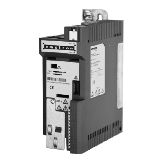
- Page 1 Emotron VS10 / VS30 AC drive 0.33 … 3 hp Use in UL approved systems Mounting and switch on instruction...
- Page 2 This page intentionally left blank!
- Page 3 Contents Contents 1 General information 1.1 Read first, then start 1.2 Notations and conventions 1.2.1 Product code 2 Safety instructions 2.1 Basic safety measures 2.2 Residual hazards 2.3 Application as directed 3 Product description 4 Mounting 4.1 Important notes 4.2 Mechanical installation 4.3 Electrical installation 4.3.1 Important notes...
- Page 4 This page intentionally left blank!
-
Page 5: General Information
Please observe the safety instructions! Information and tools with regard to the Lenze products can be found on the Internet: http://www.emotron.com / file-archive Notations and conventions 1.2.1 Product code, examples: VS10-23-1P7-20-CM VS10-40-1P7-20-CM Series 1-phase 230V Rated current 1.7A IP20 CANopen & Modbus... -
Page 6: Safety Instructions
Safety instructions Basic safety measures Safety instructions Basic safety measures Disregarding the following basic safety measures may lead to severe personal injury and damage to material assets! The product • must only be used as directed. • must never be commissioned if they display signs of damage. •... -
Page 7: Residual Hazards
Safety instructions Residual hazards Residual hazards The user must take the residual hazards mentioned into consideration in the risk assessment for his/her machine/system. If the above is disregarded, this can lead to severe injuries to persons and damage to material assets! Product Observe the warning labels on the product! Icon... -
Page 8: Product Description
Product description Product description Earth / ground connection (PE) Mains voltage connection X100 Relay output X9 IT screw from 0.55 kW Network X2xx Memory module X20 CANopen/Modbus (Option) Network status-LEDs Inverter status LEDs Shield connection CANopen/Modbus Toggle switch CANopen/Modbus Interface X16 Diagnostic module Shield connection... -
Page 9: Mounting
Mounting Important notes Mounting Important notes DANGER! Dangerous electrical voltage Possible consequence: death or severe injuries ▶ All work on the inverter must only be carried out in the deenergised state. ▶ After switching off the mains voltage, wait for at least 3 minutes before you start working. -
Page 10: Mechanical Installation
Mounting Mechanical installation Mechanical installation Dimensions 0.33 hp ... 0.5 hp All dimensions in inches... - Page 11 Mounting Mechanical installation Dimensions 0.75 hp ... 1 hp All dimensions in inches...
- Page 12 Mounting Dimensions 1.5 hp ... 3 hp All dimensions in inches...
-
Page 13: Electrical Installation
Mounting Electrical installation Mechanical installation Important notes Electrical installation 4.3.1 Important notes WARNING! ▶ The integral solid state short circuit protection included in the inverter does not provide branch circuit protection. Branch circuit protection must be provided in accordance with the National Electrical Code and any additional local codes. -
Page 14: Phase Mains Connection 230/240 V
Mounting Electrical installation 1-phase mains connection 230/240 V 4.3.2 1-phase mains connection 230/240 V WARNING! ▶ Suitable for use on a circuit capable of delivering not more than 5,000 rms symmetrical amperes, 240 V maximum. ▶ When protected by fuses rated as given in tables below. ▶... - Page 15 Mounting Electrical installation 1-phase mains connection 230/240 V The wiring diagram is valid for Emotron VS10 inverters. 3/N/PE 3/N/PE 2/N/PE AC 400 V AC 208 V ... 240 V AC 208 V ... 240 V … … 1/N/PE 2/PE 2/PE AC 170 V ...
-
Page 16: Fusing And Terminal Data
Mounting Electrical installation 1-phase mains connection 230/240 V 4.3.2.1 Fusing and terminal data Inverter VS10231P7 VS10232P4 VS10233P2 VS10234P2 VS10236P0 VS10237P0 VS10239P6 Cable installation in compliance with Operation without mains choke Fuse Characteristic all acc. to UL 248/CC Max. rated current Circuit breaker Characteristic Max. -
Page 17: Phase Mains Connection 230/240 V
Mounting Electrical installation 1/3-phase mains connection 230/240 V 4.3.3 1/3-phase mains connection 230/240 V WARNING! ▶ Suitable for use on a circuit capable of delivering not more than 5,000 rms symmetrical amperes, 240 V maximum. ▶ When protected by fuses rated as given in tables below. ▶... - Page 18 The wiring diagram is valid for Emotron VS30 inverters. Emotron VS30 inverters do not have an integrated EMC filter in the AC mains supply. In order to comply with the EMC requirements according to EN 61800−3, an external EMC filter according to IEC EN 60939 has to be used.
-
Page 19: Fusing And Terminal Data
Mounting Electrical installation 1/3-phase mains connection 230/240 V 4.3.3.1 Fusing and terminal data Inverter VS30231P7 VS30232P4 VS30233P2 VS30234P2 VS30236P0 VS30237P0 VS30239P6 Cable installation in compliance with Operation without mains choke Fuse Characteristic all acc. to UL 248/CC Max. rated current Circuit breaker Characteristic Max. -
Page 20: Phase Mains Connection 480 V
Mounting Electrical installation Fusing and terminal data 4.3.4 3-phase mains connection 480 V WARNING! ▶ Suitable for use on a circuit capable of delivering not more than 5,000 rms symmetrical amperes, 480/277 V maximum. ▶ When protected by fuses rated as given in tables below. ▶... - Page 21 Mounting Electrical installation 3-phase mains connection 480 V The wiring diagram is valid for Emotron VS30 inverters. 3/N/PE AC 480 V … 3/PE AC 340 V ... 528 V 45 Hz ... 65 Hz CAN open/Modbus Modbus AC 240 V...
-
Page 22: Fusing And Terminal Data
Mounting Electrical installation Fusing and terminal data 4.3.4.1 Fusing and terminal data Inverter VS30401P3 VS30401P8 VS30402P4 VS30403P2 VS30403P9 VS30405P6 Cable installation in compliance with Operation without mains choke Fuse Characteristic all acc. to UL 248/CC Max. rated current Operation with mains choke Fuse Characteristic all acc. -
Page 23: Canopen/Modbus
Mounting CANopen / Modbus 4.3.5 CANopen/Modbus Typical topologies Line X216 X216 X216 X216 Basic network settings 1. Use toggle switch on front of the inverter to select CANopen or Modbus network. 2. Set node address and baud rate via corresponding parameters. Terminal description CANopen/Modbus Connection... -
Page 24: Commissioning
Commissioning Important notes Commissioning Important notes WARNING! Incorrect settings during commissioning may cause unexpected and dangerous motor and system movements. Possible consequence: death, severe injuries or damage to property ▶ Clear hazardous area. ▶ Observe safety instructions and safety clearances. Before initial switch-on Prevent injury to persons and damage to property. -
Page 25: Initial Switch-On / Functional Test With Terminal Control
Commisioning Initial switch-on Initial switch-on / functional test with terminal control Target: achieve rotation of the motor connected to the inverter as quickly as possible. Requirements: • The connected motor matches the inverter in terms of power. • The parameter settings comply with the delivery status (Lenze setting). 1. - Page 26 2. Stop inverter again: X3/DI1 = LOW. The functional test is completed. The commissioning process of the drive solution is described in a separate commissioning instruc- tion which can be found on the Internet in our download area: http://www.emotron.com / file-archive...
-
Page 27: Technical Data
Technical data Standards and operating conditions Technical data Standards and operating conditions Conformities 2014/35/EU Low-Voltage Directive 2014/30/EU EMC Directive (reference: CE-typical drive system) TR TC 004/2011 Eurasian conformity: safety of low voltage equipment TP TC 020/2011 Eurasian conformity: electromagnetic compatibility of technical means RoHS 2 2011/65/EU... - Page 28 Technical data Standards and operating conditions dimensioning for rated power. Rsce ≥ 120 is to be met. Requirements to the shielded motor cable Capacitance per unit length C-core-core/C-core-shield < 75/150 ≤ 2.5 mm² / AWG 14 pF/m C-core-core/C-core-shield < 150/300 ≥...
-
Page 29: Phase Mains Connection 230/240 V
Technical data 1-phase mains connection 230/240 V Rated data 1-phase mains connection 230/240 V 6.2.1 Rated data The output currents apply to these operating conditions: • At a switching frequency of 2 kHz or 4 kHz: Max. ambient temperature 113 °F. •... -
Page 30: Phase Mains Connection 230/240 V
1/3-phase mains connection 230/240 V Rated data 1/3-phase mains connection 230/240 V Emotron VS30 inverters do not have an integrated EMC filter in the AC mains supply. In order to comply with the EMC requirements according to EN 61800−3, an external EMC filter according to IEC EN 60939 has to be used. -
Page 31: Phase Mains Connection 480 V
Technical data 3-phase mains connection 480 V Rated data 3-phase mains connection 480 V 6.4.1 Rated data The output currents apply to these operating conditions: • At a switching frequency of 2 kHz or 4 kHz: Max. ambient temperature 113 °F. •... - Page 32 Technical data...
- Page 33 © 06/2016 | 13506611 | 2.0 / 01-6405-01R2 CG DRIVES & AUTOMATION Mörsaregatan 12, Box 222 25 SE- 250 24 Helsingborg, Sweden +46 42 16 99 00 Info: info.se@cgglobal.com Order: order.se@cgglobal.com...
Need help?
Do you have a question about the VS10 and is the answer not in the manual?
Questions and answers