
Related Manuals for Emotron FLD48-058-20


Summary of Contents for Emotron FLD48-058-20
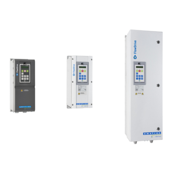
- Page 1 Emotron FlowDrive Waste water pumping AC drive Emotron FLD48/52/69, frame sizes B - F/FA/F69 and C2 - F2/FA2 0.75 - 200 kW Installation & Getting started instruction...
- Page 3 Emotron FlowDrive Emotron FLD48/52/69, frame sizes B - F/F69 and C2 - F2 0.75 - 200 kW Installation & getting started instruction. Document number: 01-6142-01 Edition: r2 Date of release: 26-03-2018 © Copyright CG Drives & Automation Sweden AB 2015 - 2018 CG Drives &...
-
Page 5: Safety Instructions
Safety Instructions Congratulations for choosing a product from CG Drives & disconnected from the AC drive first. Wait at least minutes Automation! before starting work. Before you begin with installation, commissioning or powering up the unit for the first time it is very important Earthing that you carefully study this Instruction manual. - Page 6 Mains voltage selection Heat warning The AC drive may be ordered for use with the mains voltage range listed below. HOT SURFACE! Be aware of specific parts on the AC FLD48: 230-480 V drive having high temperature. FLD52: 440-525 V FLD69: 500-690 V DC-link residual voltage Voltage tests (Megger)
-
Page 7: Table Of Contents
Contents Safety Instructions........1 7.12 EMC filter class C1/C2 ........58 7.13 Output chokes ..........58 Contents............. 3 7.14 Liquid cooling............ 58 7.15 Top cover for IP20/21 version ......58 Introduction..........5 7.16 Other options ............ 58 Using of the instruction manual......5 Technical Data ........ - Page 8 CG Drives & Automation, 01-6142-01r2...
-
Page 9: Introduction
Introduction Glossary 1.2.1 Abbreviations and symbols Emotron FlowDrive is an AC drive dedicated for controlling wastewater pumps with focus on continuous pumping with In this manual the following abbreviations are used: best economy (lowest cost). FlowDrive can operate as a... -
Page 10: Warranty
Warranty The warranty applies when the equipment is installed, operated and maintained according to instructions in this instruction manual. Duration of warranty as per contract. Faults that arise due to faulty installation or operation are not covered by the warranty. Introduction CG Drives &... -
Page 11: Mounting
Mounting This chapter describes how to mount the AC drive. Stand-alone units Before mounting it is recommended that the installation is The AC drive must be mounted in a vertical position against planned out first. a flat surface. Use the template (in the File archive on our homepage) to mark out the position of the fixing holes. - Page 12 (26.5 lb) Fig. 3 Emotron FLD Model 48/52-003 to 018 (Frame size B) Fig. 5 Emotron FLDModel 48/52-003 to 018 (Frame size B) example with optional CRIO interface and D-sub connectors. Table 4 Dimensions connected to Fig. 3. Dimensions in mm (in)
- Page 13 7mm (x4) (0.27 in) 24 kg (53 lb) 17 kg (38 lb) Fig. 6 Emotron FLD Model 48/52-026 to 046 (Frame size Fig. 8 Emotron FLD Model 48-025 to 48-058 (Frame size C2), backside view. Gland M25 (026-031) Glands M32 (037-046)
- Page 14 Glands Fig. 11 Cable interface for mains, motor and communication, Emotron FLD Model 48/52-061 and 074 (Frame Fig. 13 Bottom view Emotron FLD Model 48-072 to 48-088 size D). (Size D2), with cable interface for mains, motor, DC+/DC-, brake resistor and control.
- Page 15 56/60 kg 74 kg (124/132 lb) (163 lb) Fig. 14 Emotron FLD Model 48-090 to 175 (Frame size E). Fig. 16 Emotron FLD Model 48-210 to 295 (Frame size F) Emotron FLD Model 69-090 to 200 (Frame size F69). Cable glands M20...
- Page 16 48-171 (Frame size E2). 48-293 (Frame size F2) and 48-365 (Frame size FA and FA2). Fig. 19 Bottom view Emotron FLD Model 48-106 to 48-293 (Frame size E2 and F2), with cable interface for mains, motor, DC+/DC-, brake resistor and control.
-
Page 17: Installation
Installation The description of installation in this chapter complies with 3.1.1 Remove/open front cover the EMC standards and the Machine Directive. Frame sizes B - FA(IP54) Select cable type and screening according to the EMC Remove/open the front cover to access the cable connections requirements valid for the environment where the AC drive and terminals. -
Page 18: Cable Connections
3.1.2 Remove/open the lower front Cable connections cover on Frame size E2, F2 IP54-FLD48/52-003 to 074 (Frame sizes B, C and D) IP20/21 - FLD48 025 to 293 (Frame sizes C2,D2,E2 and FA2 (IP20/21) and F2). 3.2.1 Mains cables Dimension the mains and motor cables according to local regulations. - Page 19 Strainrelief and EMC clamp for brake resistor cables (option) EMC gland, Screen connec of motor cables Fig. 23 Mains and motor connections, model 003-018, frame size B Strainrelief and EMC clamp for screen connection of cables Fig. 25 Mains and motor connections model 48-025 to 48- 058, frame size C2.
- Page 20 Strainrelief and EMC clamp for brake resistor cables (option) Strainrelief and EMC clamp also for screen connection Strainrelief and EMC clamp also for screen connection of cables of cables Fig. 27 Mains and motor connections model 48-072 to 48-105, frame size D2. Fig.
- Page 21 3.2.2 Motor cables To comply with the EMC emission standards the AC drive Table 9 Mains and motor connections is provided with a RFI mains filter. The motor cables must also be screened and connected on both sides. In this way a L1,L2,L3 Mains supply, 3 -phase Safety earth (protected earth)
- Page 22 Connect the motor cables according to U - U, V - V and Pay special attention to the following points: W - W, see Fig. 23, to Fig. 29 . • If paint must be removed, steps must be taken to prevent subsequent corrosion.
-
Page 23: Connection Of Motor And Mains Cables For Larger Frame Sizes
RFI-Filter Mains IP54 - FLD 48-090 to 295 (Frame sizes E - F) and FLD 69-090 to 200 (Frame size F69) Emotron FLD48-090 and up, Emotron Metal EMC cable FLD69-090 and up glands To simplify the connection of thick motor and mains cables to the AC drive, the cable interface plate can be removed. -
Page 24: Cable Specifications
Cable specifications 3.4.1 Stripping lengths Fig. 3.4.2 indicates the recommended stripping lengths for Table 10 Cable specifications motor and mains cables. Cable Cable specification Power cable suitable for fixed installation for the Mains voltage used. Symmetrical three conductor cable with concentric protection (PE) wire or a four Motor conductor cable with compact low-impedance... - Page 25 Fig. 37 indicates the distance from the cable clamp to the connection bolts for decision of stripping lengths for the cables. Recommended screen length for Motor and brake cables is approximate 35 mm (1.4 in). Fig. 37 Distances from the cable clamp to the connection bolts. Table 12 Distances from the cable clamp to the connection bolts for mains, motor, brake and earth cables for frame sizes FA to FA2 Mains cable Motor cable...
- Page 26 NOTE: The dimensions of the power terminals used in the cabinet drive models 300 to 3K0 can differ depending on customer specification. Table 13 Cable connector range and tightening torque for Emotron FLD48 and FLD52, according to IEC ratings. Cable cross section connector range Mains and motor...
- Page 27 Table 13 Cable connector range and tightening torque for Emotron FLD48 and FLD52, according to IEC ratings. Cable cross section connector range Mains and motor Brake Frame Model Cable type size Tightening Tightening Tightening Cable area Cable area Cable area...
- Page 28 List of cable cross section connector range with minimum required AWG cable cross section which fits to the terminals according to UL-requirements. Table 15 Cable connector range and tightening torque for Emotron FLD48 and FLD52, according to NEMA ratings Cable cross section connector range...
-
Page 29: Thermal Protection On The Motor
Thermal protection on the motor Standard motors are normally fitted with an internal fan. The cooling capacity of this built-in fan is dependent on the frequency of the motor. At low frequency, the cooling capacity will be insufficient for nominal loads. Please contact the motor supplier for the cooling characteristics of the motor at lower frequency. - Page 30 Installation CG Drives & Automation, 01-6142-01r2...
-
Page 31: Control Connections
Control Connections Control board WARNING! Always switch off the mains voltage and Fig. 38 shows the layout of the control board which is where wait at least 7 minutes to allow the DC the parts most important to the user are located. Although capacitors to discharge before connecting the control board is galvanically isolated from the mains, for the control signals or changing position of any... -
Page 32: Terminal Connections
Terminal connections Table 16 Control signals The terminal strip for connecting the control signals is Terminal Name Function (Default) accessible after opening the front panel. Relay outputs The table describes the default functions for the signals. The N/C 1 inputs and outputs are programmable for other functions as Relay 1 output described in the separate Software instruction. -
Page 33: Inputs Configuration With The Switches
NOTE: the 2 analogue outputs AnOut 1 and AnOut 2 Single pump or two pump configuration can be configured using the software. See menu [530] Emotron FlowDrive can work in three different modes: in the separate Software instruction. • Stand alone - One single pump •... - Page 34 4.4.1 Minimum wiring examples Stand alone Follower Master Auto/Off/Manual Auto/Off/Manual Auto/Off/Manual switch switch switch Manual Manual Manual Auto Auto Auto Level sensor Level sensor + 10 VDC + 10 VDC + 10 VDC AnIn 1 AnIn 1 AnIn 1 0 VDC 0 VDC DigIn 1 DigIn 1...
- Page 35 4.4.2 Full wiring examples FlowDrive Stand alone 0 VDC +10 VDC AnOut 1 AnIn 1 Level sensor AnIn 2 AnOut 2 AnIn 3 Flow sensor DigOut 1 Personal protection alarm DigOut 2 AnIn 4 -10 VDC 0 VDC Manual DigIn 1 Relay 1 Auto DigIn 2...
- Page 36 FlowDrive Master / Follower FlowDrive FlowDrive Follower Master 0 VDC 0 VDC +10 VDC +10 VDC AnOut 1 AnOut 1 Level sensor AnIn 1 AnIn 1 AnOut 2 AnOut 2 AnIn 2 AnIn 2 DigOut 1 DigOut 1 Flow sensor AnIn 3 AnIn 3 AnIn 4...
- Page 37 4.4.3 Connecting the Control Signal cables The standard control signal connections are suitable for stranded flexible wire up to 1.5 mm (AWG16) and for solid wire up to 2.5 mm (AWG14) . Terminal 78 & 79 NOTE: The screening of control signal cables must see Table 19 comply with the immunity levels given in the EMC Directive (reduction of noise level).
- Page 38 Terminal 78 & 79 see Table 19 Terminal A- & B+ see Table 19 Screen clamps for signal cables Screen clamps for signal cables Control signals Control signals Fig. 46 Connecting the control signals, FLD model 061 to 074, frame size D. Fig.
- Page 39 Example: The relay output from a AC drive which controls an auxiliary relay can, at the moment of switching, form a NOTE: The screening of control signal cables is source of interference (emission) for a measurement signal necessary to comply with the immunity levels given in the EMC Directive (it reduces the noise level).
-
Page 40: Connecting Options
4.4.7 Current signals ((0)4-20 mA) Control board A current signal like (0)4-20 mA is less sensitive to disturbances than a 0-10 V signal, because it is connected to Pressure sensor an input which has a lower impedance (250 Ω) than a (example) voltage signal (20 kΩ). -
Page 41: Getting Started
We assume that: Emotron FlowDrive - IP54 and IP2X versions, has a control • the AC drive is mounted on a wall or in a cabinet as in panel with a two line display and buttons according to Fig. - Page 42 Digits Description Bit* Motor is stopped 4161MaxAlarm Mar Run Motor runs Acc Acceleration Dec Deceleration Tripped Fig. 56 Example 4th level menu Operating Safe Stop, is flashing when activated 5.2.2 Indications on the display Operating at voltage limit The display can indicate “+++” or “- - -” if a parameter is out Operating at speed limit of range.
- Page 43 5.2.4 Control keys To access submenus to menu [221], press Toggle to enter menu [221] then use the Next key to In FlowDrive mode only the Stop/Reset button is used to enter the sub menus [222] to [22H] and enter the reset the AC drive after a trip.
-
Page 44: Control Panel With Four Lines Display
The function keys operate the menus and are also used for lines display programming and read-outs of all the menu settings. Emotron FlowDrive - IP54 and IP2X have a control panel with a four lines display according to Fig. 59. Table 22 Function keys This control panel is equipped with real time clock function. - Page 45 Area D *: Shows the status of the AC drive (3 digits). Area J Active control source The following status indications are possible: Digits Description Digits Description Bit* Flowdrive level control not activated Motor is stopped Standby (Pump not running) Motor runs Flushing (flushing pipes) Acceleration...
- Page 46 Menu [100] Preferred view This menu is displayed at every power-up. During operation, the menu [100] will automatically be displayed when the keyboard is not operated for 5 minutes. Menu “[100] Preferred View” displays the settings made in menu “[110], 1st line”, “[120], 2nd line” and “[130], 3rd line”.
- Page 47 5.3.4 Real Time clock 5.3.5 LED indicators In this 4 lines Control panel (PPU) there is a built in Real The symbols on the control panel have the following time clock. This means that actual date and time will be functions: shown at e.g.
- Page 48 5.3.6 Function keys Example: Setting Motor data. The function keys operate the menus and are also used for programming and read-outs of all the menu settings. Menu [100], “Preferred View” is displayed when started. 1. Press to display menu [200], “Main Setup”. step to lower menu level or confirm 2.
-
Page 49: Basic Configuration (All Ac Drives)
Generic drive mode it behaves like a with configuration of Master unit below and then copy normal Emotron FDU drive. By default the AC drive is common parameters as outlined later in this guide. configured in WasteWater mode and the remaining quick NOTE: Setting the parameter to “Follower”... -
Page 50: Standalone / Master Configuration
Standalone / Master dependent on the sensor but often sensors with a range of 5 or 10 meters is used. configuration See also Fig. 64, page 47. Regarding more advanced functions please refer to the NOTE: “5.4 Basic configuration (all AC drives)” should separate Software instruction manual be done before entering here. - Page 51 Overflow Level switch Area calculation: (optional) [3A21]Overflow Level [3A22]Start Level r = diameter/2 [3A35]Level 3 / [3A36]Area 3 [3A33]Level 2 / [3A34]Area 2 [3A23]Stop Level [3A31]Level 1 / [3A32]Area 1 Fig. 64 Sump areas and levels, examples. Example with round reservoir: Example with rectangular reservoir: Level= X m, Level= X m,...
-
Page 52: Copy To Follower
Examples of reservoir shapes and levels Copy to follower Following are examples of different reservoir shapes and In case of a Master and Follower system it is now time to levels required. copy parameters to the follower. On a “Standalone” system skip this part. -
Page 53: Engage "Auto Tune" Program To Optimize Energy Consumption
Engage “Auto Tune” Configuration of program to optimize additional features energy consumption (optional) When concluded that the FlowDrive appears to be running Here is an overview of some of the additional features built correctly in Auto mode as described earlier, the “Auto Tune” into the FlowDrive, More detailed information can be found program can be started. - Page 54 NOTE 1: Running pumps below their normal stop level might cause the pump to overheat. NOTE 2: Problems might emerge from sucking air into the pump/pipes in some installations (generally dry setups). NOTE 3: The load drop percentage Δ ([3B43] Off Torque ), i.e.
-
Page 55: Emc And Standards
EMC and standards EMC standards Stop categories and emergency stop The AC drive complies with the following standards: EN(IEC)61800-3:2004 Adjustable speed electronic power The following information is important if emergency stop drive systems, part 3, EMC product standards: circuits are used or needed in the installation where a AC drive is used. - Page 56 EMC and standards CG Drives & Automation, 01-6142-01r2...
-
Page 57: Options
Options The standard options available are described here briefly. NOTE: The 4-lines Control panel requires Some of the options have their own instruction or software 1.20 or later. installation manual. For more information please contact your supplier. See also in “Technical catalogue AC drives” for more info. -
Page 58: Handheld Control Panel 2.0
Handheld Control Panel Gland kits Gland kits are available for frame sizes B, C and D. Metal EMC glands are used for motor and brake resistor cables. Part number Description Handheld Control Panel 2.0 complete for Frame 01-5039-00 Part Number Current (dimension) FlowDrive including 2-lines panel size... -
Page 59: Rtc- Real Time Clock Board
RTC- Real time clock 7.10 Standby power supply board Part no. AC drive Version Note Part number Description IP20/21 and IP54/20 Factory 01-3876-15 RTC option board - Coated frame sizes B - F mounted - Coated option With this option board connected, it is possible to see and Factory IP2Y frame sizes A3 - C3 mounted or... - Page 60 this safety circuit ensures that the motor will not start running because: • The 24VDC signal is disconnected from the "Inhibit" input, terminals 1 and 2, the safety relay K1 is switched off. The supply voltage to the driver circuits of the power conductors is switched off.
- Page 61 Table 24 Specification of Safe Stop option board Name Function Specification Inhibit + Inhibit driver circuits of DC 24 V power conductors (20–30 V) Inhibit - NO contact Feedback; relay K2 48 V confirmation of 30 V /2 A P contact activated inhibit relay K2 Supply ground...
-
Page 62: Emc Filter Class C1/C2
7.12 EMC filter class C1/C2 EMC filter according to EN61800-3:2004 class C1 (for frame size C types) and C2 - 1st environment restricted distribution. For sizes B, C, C2, D and D2, the filter is mounted inside the drive module. For sizes E , external EMC filters are available. -
Page 63: Technical Data
Technical Data Electrical specifications related to model Emotron FLD - IP20/21 version Table 25 Typical motor power at mains voltage 230, 400 and 460V. AC drive main voltage range 230 - 480 V. Normal duty Max. (120%, 1 min every 10 min) - Page 64 Emotron FLD - IP54 version Table 26 Typical motor power at mains voltage 230, 400 and 460 V. AC drive main voltage range 230 - 480 V. Normal duty Max. (120%, 1 min every 10 min) output Frame Model Rated...
- Page 65 Emotron FLD 2.0 - IP54 version (Model 69-250 and up also available as IP20) Table 27 Typical motor power at mains voltage 525, 575 and 690 V. AC drive main voltage range, for 52: 440 - 525 V and for 69: 500 - 690 V.
-
Page 66: General Electrical Specifications
General electrical specifications Table 28 General electrical specifications General Mains voltage: 230-480V +10%/-15% (-10% at 230 V) 440-525 V +10 %/-15 % 500-690V +10%/-15% Mains frequency: 45 to 65 Hz Mains voltage imbalance: max. +3.0% of nominal phase to phase input voltage. Input power factor: 0.95 Output voltage:... -
Page 67: Operation At Higher Temperatures
Operation at higher temperatures switching frequency Most Emotron AC drives are made for operation at Table 29 shows the switching frequency for the different AC maximum of 40°C (104 °F) ambient temperature. However, drive models. With the possibility of running at higher... -
Page 68: Dimensions And Weights
90 to 200 1090 x 345 x 314 (42.9 x 13.6 x 12.4) 77 (169.8) Dimensions and weights for models Emotron 48 - IP20/21 version The table below gives an overview of the dimensions and weights of the Emotron IP20/21 version. -
Page 69: Environmental Conditions
Environmental conditions Table 33 Operation Parameter Normal operation ° ° ° ° Nominal ambient temperature C–40 C (32 F - 104 F) See table, see chapter 8.3 page 63 for different conditions Atmospheric pressure 86–106 kPa (12.5 - 15.4 PSI) Relative humidity Class 3K4, 5...95% and non condensing according to IEC 60721-3-3... -
Page 70: Fuses And Glands
Fuses and glands 8.7.1 According to IEC ratings NOTE: The dimensions of fuse and cable cross-section are dependent on the application and must be Use mains fuses of the type gL/gG conforming to IEC 269 determined in accordance with local regulations. or breakers with similar characteristics. - Page 71 Table 35 Fuses, cable cross-sections and glands Nominal input Maximum Cable glands (clamping range ) * Model current value fuse mains / motor Brake 48: (Ø17-42 mm (0.67 - 1.65 in)) 48: (Ø11-32 mm(0.43 - 1.26 in)) cable flexible leadthrough or M50 Cable flexible leadthrough or M40 opening.
- Page 72 8.7.2 Fuses according to NEMA ratings Table 36 Types and fuses Mains input fuses Input Ferraz- Model current Class J TD Shawmut [Arms] type 48-003 AJT6 48-004 AJT6 48-006 AJT6 48-008 AJT10 48-010 AJT10 48-013 11.3 AJT15 48-018 15.6 AJT20 48-025 21.7 AJT25...
-
Page 73: Control Signals
Control signals Table 37 Terminal Name: Function (Default): Signal: Type: +10 V +10 VDC Supply voltage +10 VDC, max 10 mA output 0 -10 VDC or 0/4–20 mA AnIn1 Level sensor bipolar: -10 - +10 VDC or -20 - +20 analogue input 0 -10 VDC or 0/4–20 mA AnIn2... - Page 74 Technical Data CG Drives & Automation 01-6142-01r2...
-
Page 75: Menu List
Menu List Factory setting Customer On our home page in the download area, you could find a 230 Mot Protect "Communication information" list and a list to note Parameter Mot I t Type Trip set information. Mot I t Curr 100% Mot I t Time... - Page 76 Factory setting Customer Factory setting Customer Ethernet 3B0 Functions 2651 IP Address 0.0.0.0 Flush start 2652 MAC Address 000000000000 3B11 Flush time 2653 Subnet Mask 0.0.0.0 3B12 Flush speed 50Hz 2654 Gateway 0.0.0.0 Start lvl 2655 DHCP PumpCleaning FB Signal 3B31 Act.PumpCln No 2661 FB Signal 1 3B32 ForcePumpCl Off...
- Page 77 Factory setting Customer Factory setting Customer 340 Speed 4412 Delay 1 Min speed 50Hz 4413 Active pol 1 High Max speed Sync speed 4414 Autoreset 1 BEP Speed 4415 Trip name 1 User defined 350 Torques 4416 Trip text 1 User trip 1 Max Torque 120%...
- Page 78 Factory setting Customer Factory setting Customer 5192 AnIn3 Max 20.00mA 5364 AnOut2 FcMin Min 5193 AnIn3 Bipol 20.00mA 5365 AnOut2 VaMin 0 5194 AnIn3 FcMin AnOut2 5366 FcMax 5195 AnIn3 VaMin AnOut2 5196 AnIn3 FcMax Max 5367 VaMax 5197 AnIn3 VaMax 0 540 Dig Outputs 5198 AnIn3 Oper Add+...
- Page 79 Factory setting Customer Factory setting Customer 6115 CA1 Polar Unipolar Counter 2 CA2 Setup 6621 C2 Trig 6121 CA2 Value Torque 6622 C2 Reset 6122 CA2 LevelHI 6623 C2 High Val 6123 CA2 LevelLO 10 6624 C2 Low Val 6124 CA2 Type Hysteresis 6625 C2 DecTimer Off 6125 CA2 Polar...
- Page 80 Factory setting Customer Factory setting Customer Mains Time 00:00:00 8117 Output volt Energy 8118 Frequency 7331 Energy tot ...kWh 8119 DC Voltage 7332 Energy P1 ...kWh 811A IGBT Tmp 7333 Energy P2 ...kWh 811B PT100 1,2,3 7334 Energy Day Speed 7335 P1EnergyDay 8121 VSD Status 7336 P2EnergyDay...
- Page 81 Factory setting Customer Freq: XX.x Hz + submenus 9431 - 9433 Freq: XX.x Hz + submenus 9441 - 9443 Freq: XX.x Hz + submenus 9451 - 9453 Freq: XX.x Hz + submenus 9461 - 9463 Freq: XX.x Hz + submenus 9471 - 9473 Freq: XX.x Hz + submenus 9481 - 9483 Freq: XX.x Hz + submenus 9491 - 9493 Freq: XX.x Hz + submenus 94A1 - 94A3...
- Page 82 Menu List CG Drives & Automation, 01-6142-01r2...
- Page 84 CG Drives & Automation Sweden AB Mörsaregatan 12 Box 222 25 SE-250 24 Helsingborg Sweden T +46 42 16 99 00 F +46 42 16 99 49 www.emotron.com/www.cgglobal.com...
Need help?
Do you have a question about the FLD48-058-20 and is the answer not in the manual?
Questions and answers