Table of Contents
Advertisement
Quick Links
Advertisement
Table of Contents

Related Manuals for Measurement Computing USB-1616FS


Summary of Contents for Measurement Computing USB-1616FS
- Page 2 USB-1616FS Measurement Advantage™ brand USB-based Analog and Digital I/O User's Guide Document Revision 3, March, 2005 © Copyright 2005, Measurement Computing Corporation™...
- Page 3 Measurement Computing. Thank you for choosing a Measurement Computing product—and congratulations! You own the finest, and you can now enjoy the protection of the most comprehensive warranties and unmatched phone tech support. It’s the embodiment of our two missions: To offer the highest-quality, computer-based data acquisition, control, and GPIB hardware and software available—...
- Page 4 Information furnished by Measurement Computing Corporation is believed to be accurate and reliable. However, no responsibility is assumed by Measurement Computing Corporation neither for its use; nor for any infringements of patents or other rights of third parties, which may result from its use. No license is granted by implication or otherwise under any patent or copyrights of Measurement Computing Corporation.
-
Page 5: Table Of Contents
Trigger terminal ................................3-7 SYNC terminal ................................3-7 Daisy chaining additional modules to the USB-1616FS ................3-7 Sample rate limitations when using multiple USB-1616FS devices ................3-8 Power limitations when using multiple USB-1616FS devices..................3-8 Accuracy................................. 3-8 Gain queue..............................3-11... - Page 6 USB-1616FS User's Guide Chapter 4 Specifications ............................ 4-1 Analog input section............................4-1 Single board throughput..............................4-2 Multiple board throughput ............................. 4-2 Throughput benchmarks ..............................4-3 Usage note ..................................4-3 Digital input/output ............................4-4 External trigger............................... 4-4 External clock input/output ..........................4-4 Counter section...............................
-
Page 7: Preface
What you will learn from this user's guide This user's guide explains how to install, configure, and use the USB-1616FS so that you get the most out of its analog and digital I/O features. This user's guide also refers you to related documents available on our web site, and to technical support resources. -
Page 9: Introducing The Usb-1616Fs
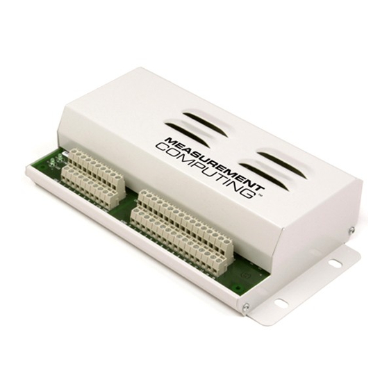
USB port in a daisy chain fashion. The USB-1616FS is enclosed in a rugged housing that you can mount on a DIN rail or on a bench. The USB-1616FS is shown in Figure 1-1. -
Page 10: Usb-1616Fs Block Diagram
USB-1616FS User's Guide Introducing the USB-1616FS USB-1616FS block diagram USB-1616FS functions are illustrated in the block diagram shown here. Screw terminal I/O connector Cal Ref Voltages Temp. Sensor G= 1, 2, 5, 10 32-bit Event Counter 1 channel Full-speed USB 2.0... -
Page 11: Software Features
Microsoft HID because it is a standard, and its performance delivers full control and maximizes data transfer rates for your USB-1616FS. No third-party device driver is required. The USB-1616FS is plug-and-play. There are no jumpers to position, DIP switches to set, or interrupts to configure. -
Page 13: Installing The Usb-1616Fs
Chapter 2 Installing the USB-1616FS What comes with your USB-1616FS shipment? As you unpack your USB-1616FS, verify that the following components are included. Hardware USB-1616FS USB cable (24 AWG VBUS/GND, 2 meter length) External power supply and cord (CB-PWR-9V3A) – 9 volt, 3 amp DC power supply... -
Page 14: Documentation
As with any electronic device, you should take care while handling to avoid damage from static electricity. Before removing the USB-1616FS from its packaging, ground yourself using a wrist strap or by simply touching the computer chassis or other grounded object to eliminate any stored static charge. -
Page 15: Connecting The Usb-1616Fs To Your System
"Notes on installing and using the USB-1616FS" that was shipped with the USB-1616FS. If you are running Windows XP and connect the USB-1616FS to a USB 1.1 port, a balloon displays the message " ." You can ignore this Your USB device can perform faster if you connect to a USB 2.0 port... - Page 16 Removing USB-1616FS boards from Windows XP systems Device Manager may require up to 30 seconds to detect the removal of a USB-1616FS board from a Windows XP system with Service Pack 1 or Service Pack 2 installed. This time increases with each additional connected board.
-
Page 17: Functional Details
USB-1616FS FIFO buffer to the memory buffer on your computer. You can acquire data with the USB-1616FS from one channel at 50 kS/s and up to 16 channels at 9.5 kS/s each. Table 4-1 on page 4-2 lists the throughput rates for 1 to 16 channels. You can start a continuous scan with either a software command or with an external hardware trigger event. -
Page 18: Internal Components
USB-1616FS User's Guide Functional Details Internal components Major components on the USB-1616FS are shown in Figure 3-1. Two (2) USB connectors Two (2) external power connectors USB LED PWR LED Four (4) Screw terminal banks USB IN POWER IN POWER... -
Page 19: External Power Connectors
4.75 V to 5.25 V External power: (+9 V): 6.0 V to 12.5 V Screw terminal wiring The USB-1616FS has two rows of screw terminals. Each row has 26 connections. Signal labels are shown in Figure 3-2. Figure 3-2. USB-1616FS screw terminals... -
Page 20: Analog Input Terminals (Ch0 In To Ch15 In)
USB-1616FS User's Guide Functional Details The screw terminals provide the following connections: eight digital I/O terminals ( DIO 0 DIO 7 one external digital trigger terminal ( TRIG IN one power terminal ( eight ground terminals ( GND 0 one external event counter terminal (... -
Page 21: Digital I/O Terminals (Dio0 To Dio7)
USB-1616FS User's Guide Functional Details Input configuration All of the analog input channels are configured for single-ended input mode. Each analog signal is referenced to a signal ground (AGND), and requires two wires: The wire carrying the signal to be measured connects to CH# IN. -
Page 22: Power Terminals
USB-1616FS User's Guide Functional Details When you configure the digital bits for input, you can use the USB-1616FS digital I/O terminals to detect the state of any TTL-level input. Refer to the switch circuit shown in Figure 3-5 and the schematic shown in Figure 3-6. -
Page 23: Counter Terminal
SYNC supports TTL-level input signals. Configure as an output to synchronize with a second USB-1616FS and acquire data from 32 channels. Refer to the pinout diagram on page 3-4 for the location of this pin. For more information, refer to "Synchronizing multiple... -
Page 24: Sample Rate Limitations When Using Multiple Usb-1616Fs Devices
Power limitations when using multiple USB-1616FS devices When daisy chaining additional Measurement Advantage products to the USB-1616FS, you must ensure that you provide adequate power to each board that you connect. The USB-1616FS is powered with a 9 VDC nominal, 3.0 A external power supply. - Page 25 32768. Any deviation from this is an offset error. Figure 3-9 shows the USB-1616FS transfer function with an offset error. The typical offset error specification for the USB-1616FS on the ±10 V range is ±1.66 mV. Offset error affects all codes equally by shifting the entire transfer function up or down along the input voltage axis.
- Page 26 Combining these two error sources in Figure 3-11, we have a plot of the error band of the USB-1616FS at ±full scale (±10 V). This plot is a graphical version of the typical accuracy specification of the product.
-
Page 27: Gain Queue
Gain queue The USB-1616FS gain queue allows you to set up a different gain setting for each channel. The gain queue removes the restriction of having a single gain for all channels. This feature creates a gain list which is written to local memory on the USB-1616FS. - Page 28 (unchecked is the default Enable Sync output setting). 5. Connect the SYNC pin of the master USB-1616FS to the SYNC pin of the slave USB-1616FS. 6. Set the Universal Library option with for the slave USB-1616FS...
-
Page 29: Specifications
Chapter 4 Specifications Typical for 25 °C unless otherwise specified. Specifications in italic text are guaranteed by design. Analog input section Parameter Conditions Specification A/D converters 16-bit, SAR type Number of channels 16 single-ended Input configuration Individual A/D per channel Sampling method Simultaneous Absolute maximum input... -
Page 30: Single Board Throughput
Single board throughput The USB-1616FS has an integral USB hub, which allows up to four USB-1616FS boards to be daisy chained and connected to a single USB 2.0 port on the host computer. The data shown in Table 4-1 reflects the throughput that can be expected in single board systems. -
Page 31: Throughput Benchmarks
USB-1616FS User's Guide Specifications Throughput benchmarks Throughput System 240 kS/s 2.4 GHz P4 running Win XP, Service Pack 2, using an integrated USB Enhanced Host Controller (EHC) port 240 kS/s 2.4 GHz P4, Phoenix BIOS, Win XP, Service Pack 2, integrated USB EHC port... -
Page 32: Digital Input/Output
USB-1616FS User's Guide Specifications Digital input/output Digital type CMOS Number of I/O 8 (DIO0 through DIO7) Configuration Independently configured for input or output Pull up/pull-down All pins pulled up to USB VBUS via 47 K resistors (default). Positions available for configuration pull down to ground (GND). -
Page 33: Counter Section
Available at terminal block pin 48 50 mA max. (Note 7) This is the total current requirement for the USB-1616FS which includes up to 10mA for the Note 5: status LED’s. Output voltage range assumes input power supply voltage is within specified limits... -
Page 34: Usb +5 V Voltage
MCC p/n CB-PWR-9V3A +9 V ±10%, @ 3 A The USB-1616FS monitors the external +9 V power supply voltage with a voltage supervisory Note 8: circuit. If this power supply exceeds its specified limit, the PWR LED will turn off indicating a power fault condition. -
Page 35: Mechanical
USB-1616FS User's Guide Specifications Mechanical Card dimensions 203.2 mm (L) x 121.9 mm (W) x 20.0 mm (H) 8.0" (L) x 4.8" (W) x 0.8" (H) Enclosure dimensions 208.3 mm (L) x 129.6 mm (W) x 40.6 mm (H) 8.2" (L) x 5.2" (W)x 1.6" (H) - Page 36 Middleboro, MA 02346 Category: Electrical equipment for measurement, control and laboratory use. Measurement Computing Corporation declares under sole responsibility that the product USB-1616FS to which this declaration relates is in conformity with the relevant provisions of the following standards or other documents:...
- Page 37 Measurement Computing Corporation 16 Commerce Boulevard, Middleboro, Massachusetts 02346 (508) 946-5100 Fax: (508) 946-9500 E-mail: info@mccdaq.com www.mccdaq.com...
Need help?
Do you have a question about the USB-1616FS and is the answer not in the manual?
Questions and answers