
Related Manuals for Measurement Computing USB-1408FS-Plus-OEM


Summary of Contents for Measurement Computing USB-1408FS-Plus-OEM
- Page 1 USB-1408FS-Plus-OEM Analog and Digital I/O User's Guide Document Revision 2A January 2015 © Copyright 2015...
- Page 2 Other product and company names mentioned herein are trademarks or trade names of their respective companies. © 2015 Measurement Computing Corporation. All rights reserved. No part of this publication may be reproduced, stored in a retrieval system, or transmitted, in any form by any means, electronic, mechanical, by photocopying, recording, or otherwise without the prior written permission of Measurement Computing Corporation.
-
Page 3: Table Of Contents
What you will learn from this user's guide ......................5 Conventions in this user's guide ......................... 5 Where to find more information ......................... 5 Chapter 1 Introducing the USB-1408FS-Plus-OEM ..................... 6 Functional block diagram ........................... 6 Chapter 2 Installing the USB-1408FS-Plus-OEM ....................7 Unpacking................................ - Page 4 USB-1408FS-Plus-OEM User's Guide Memory ................................23 Microcontroller ..............................23 Power ................................23 General ................................24 Environmental ..............................24 Mechanical ............................... 24 Header connector .............................. 24 Differential mode ................................25 Single-ended mode ................................25...
-
Page 5: Preface
Preface About this User's Guide What you will learn from this user's guide This user's guide describes the Measurement Computing USB-1408FS-Plus-OEM data acquisition device and lists device specifications. Conventions in this user's guide For more information Text presented in a box signifies additional information and helpful hints related to the subject matter. -
Page 6: Introducing The Usb-1408Fs-Plus-Oem
Two header connectors for field wiring connections The USB-1408FS-Plus-OEM device is compatible with both USB 1.1 and USB 2.0 ports. The speed of the device may be limited when using a USB 1.1 port due to the difference in transfer rates on the USB 1.1 versions of the protocol (low-speed and full-speed). -
Page 7: Installing The Usb-1408Fs-Plus-Oem
Installing on a Windows platform Connect the USB-1408FS-Plus-OEM to a to an available USB port on the computer running Windows, connect the USB cable to an available USB port on the computer or to an external USB hub connected to the computer. -
Page 8: Chapter 3 Functional Details
Chapter 3 Functional Details Analog input acquisition modes The USB-1408FS-Plus-OEM can acquire analog input data in either software paced or hardware paced mode. Software paced The USB-1408FS-Plus-OEM acquires data one analog sample at a time using software paced mode. You initiate the A/D conversion by calling a software command. -
Page 9: Board Components
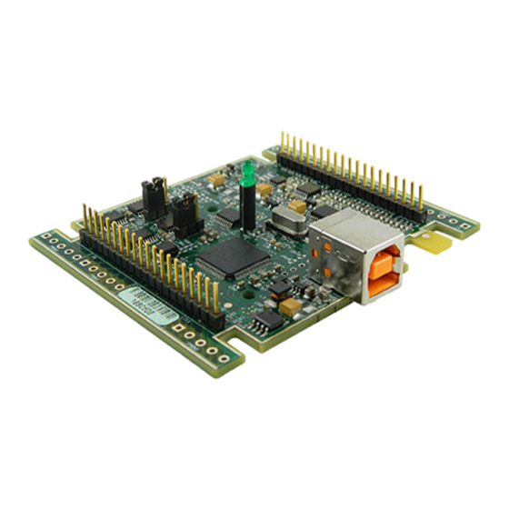
USB-1408FS-Plus-OEM User's Guide Functional Details Board components The board components – header connectors, LED, and USB connector – are shown in Figure 2. Header connector pins 21 to 40 USB connector Header connector pins 1 to 20 Figure 2. Board components USB connector Receives the supplied USB cable. -
Page 10: Differential Mode Pinout
USB-1408FS-Plus-OEM User's Guide Functional Details Differential mode pinout Four-channel differential mode pinout Signal name Pin description Signal name Pin description CH0 IN HI Analog input 0+ Port A0 Port A bit 0 CH0 IN LO Analog input 0– Port A1... -
Page 11: Signal Connections
USB-1408FS-Plus-OEM User's Guide Functional Details Signal connections Analog input You can connect up to eight analog input connections to the header connector pins 1 to 20. CH0 IN CH7 IN) You can configure the analog input channels as eight single-ended channels (... - Page 12 USB-1408FS-Plus-OEM User's Guide Functional Details For example, you input a 4 V pp sine wave to CH# IN HI, and apply the same sine wave 180° out of phase to CH# IN LO. The common mode voltage is 0 V. The differential input voltage swings from 4 V – (–4 V) = 8 V to –4 V –...
-
Page 13: Analog Output
USB-1408FS-Plus-OEM User's Guide Functional Details The table below shows some possible inputs and the expected results. Sample inputs and differential results CH# IN HI CH# IN LO Result –20 V Invalid –15 V +5 V Invalid –10 V –10 V –10 V... -
Page 14: Digital I/O
Turn the device over and rest the top of the housing on a flat, stable surface. Caution! The discharge of static electricity can damage some electronic components. Before removing the USB-1408FS-Plus-OEM from its housing, ground yourself using a wrist strap or touch the computer chassis or other grounded object to eliminate any stored static charge. -
Page 15: Counter Input
USB-1408FS-Plus-OEM User's Guide Functional Details Figure 8. Pull-up/down jumper configuration Replace the top section of the housing, and fasten it to the bottom section with the three screws. For more information on digital signal connections For more information on digital signal connections and digital I/O techniques, refer to the Guide to Signal Connections (available on our web site at www.mccdaq.com/signals/signals.pdf). - Page 16 USB-1408FS-Plus-OEM User's Guide Functional Details Figure 9 shows an ideal, error-free transfer function. The typical calibrated accuracy is range-dependent. Refer to the Accuracy specifications in Chapter 4 for more information. We use a ±10 V range here as an example of what you can expect when performing a measurement in this range.
-
Page 17: Synchronized Operations
Figure 11. ADC Transfer function with gain error For example, the USB-1408FS-Plus-OEM exhibits a typical calibrated gain error of ±0.2% on all ranges. For the ±10 V range, this would yield 10 V × ±0.002 = ±20 mV. This means that at full scale, and neglecting the effect of offset, the measurement would be within 20 mV of the actual value. -
Page 18: Power
<500 mA. The maximum output current that is available at the +VO power output terminal is 100 mA. With all outputs at their maximum output current, the USB-1408FS-Plus-OEM in a fully-loaded configuration may be above that allowed by the computer. In this case, determine the per-pin loading in the application to ensure that the maximum loading criteria is met. -
Page 19: Specifications
Chapter 4 Specifications All specifications are subject to change without notice. Typical for 25°C unless otherwise specified. Specifications in italic text are guaranteed by design. Analog input Table 1. Analog input specifications Parameter Condition Specification A/D converter type Successive approximation type Input voltage range for linear operation CHx to GND Single-ended mode: ±10 V max... -
Page 20: Accuracy
USB-1408FS-Plus-OEM User's Guide Specifications Accuracy Table 2. Accuracy, differential mode Range Absolute Accuracy 25 °C (±mV) Absolute Accuracy 0 °C to 50°C (±mV) ±20 V 10.98 49.08 ±10 V 7.32 33.42 ±5 V 3.66 20.76 ±4 V 2.92 19.02 ±2.5 V 1.83... -
Page 21: Digital Input/Output
USB-1408FS-Plus-OEM User's Guide Specifications Table 7. Analog output accuracy, all values are (±); accuracy tested at no load Range Accuracy (LSB) 0 V to 5.0 V 4.0 typ, 45.0 max Table 8. Analog output accuracy components, all values are (±) -
Page 22: External Trigger
USB-1408FS-Plus-OEM User's Guide Specifications External trigger Table 10. Digital trigger specifications Parameter Specification Trigger source (Note 7) External digital; TRIG_IN terminal Trigger mode Edge sensitive; software-selectable for CMOS compatible rising or falling edge, high or low level. Trigger latency 10 µs max Trigger pulse width 1 µs min... -
Page 23: Counter
USB-1408FS-Plus-OEM User's Guide Specifications Counter Table 12. Counter specifications Parameter Specification Pin name Counter type Event counter Number of channels Schmitt trigger, 47 kΩ pull-down to ground, rising edge triggered Input type Input source CTR header pin Resolution 32 bits... -
Page 24: General
USB-1408FS-Plus-OEM User's Guide Specifications General Table 16. General specifications Parameter Specification Device type USB 2.0 full speed Device compatibility USB 1.1, USB 2.0 Environmental Table 17. Environmental specifications Parameter Specification Operating temperature range 0 °C to 70 °C Storage temperature range –40 °C to 70 °C... -
Page 25: Differential Mode
USB-1408FS-Plus-OEM User's Guide Specifications Differential mode Table 20. 4-channel differential mode Signal name Pin description Signal name Pin description CH0 IN HI Analog input 0+ Port A0 Port A bit 0 CH0 IN LO Analog input 0– Port A1 Port A bit 1... - Page 26 Measurement Computing Corporation NI Hungary Kft 10 Commerce Way H-4031 Debrecen, Hátar út 1/A, Hungary Norton, Massachusetts 02766 Phone: +36 (52) 515400 (508) 946-5100 Fax: +36 (52) 515414 Fax: (508) 946-9500 http://hungary.ni.com/debrecen E-mail: info@mccdaq.com www.mccdaq.com...
Need help?
Do you have a question about the USB-1408FS-Plus-OEM and is the answer not in the manual?
Questions and answers