
Related Manuals for Advantech UNO-1252G Series


Summary of Contents for Advantech UNO-1252G Series
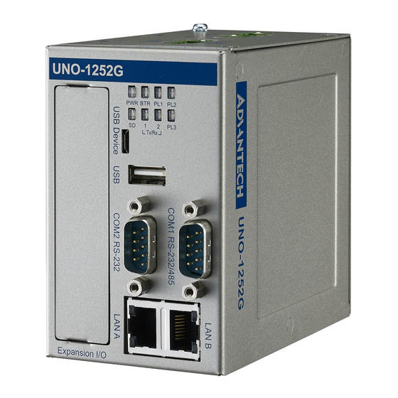
- Page 1 User Manual UNO-1252G Intel® Quark™ Palm-Size Din- Rail Automation Computer with 2 x LAN, 2 x mPCIe, 2 x COM, 8 x DI/O, 2 x USB, 1 x microSD, 1 x SIM...
- Page 2 限用物質含有情況標示聲明書 UNO-1252G 系列 設備名稱: 型號 (型式) : 電腦 Equipment name Type designation (Type) ( 系列型號參見說明書 ) 限用物質及其化學符號 Restricted substances and its chemical symbols 六價鉻 多溴聯苯 多溴二苯醚 單元 Unit 汞 鎘 Hexavalent Polybrominated Polybrominated 鉛 Lead Mercury Cadmium chromium biphenyls diphenyl ethers (Pb) (Hg) (Cd)
- Page 3 No part of this manual may be reproduced, copied, translated or transmitted in any form or by any means without the prior written permission of Advantech Co., Ltd. Information provided in this manual is intended to be accurate and reliable. How- ever, Advantech Co., Ltd.
- Page 4 This manual applies to the below model which is abbreviated as UNO-1252G series products in this article. *Model number: UNO-1252G *Part number: UNO-1252G User Manual...
- Page 5 Because of Advantech’s high quality-control standards and rigorous testing, most of our customers never need to use our repair service. If an Advantech product is defec- tive, it will be repaired or replaced at no charge during the warranty period. For out- of-warranty repairs, you will be billed according to the cost of replacement materials, service time and freight.
- Page 6 Technical Support and Assistance Visit the Advantech web site at www.advantech.com/support where you can find the latest information about the product. Contact your distributor, sales representative, or Advantech's customer service center for technical support if you need additional assistance. Please have the following information ready before you call: –...
- Page 7 The sound pressure level at the operator's position according to IEC 704-1:1982 is no more than 70 dB (A). DISCLAIMER: This set of instructions is given according to IEC 704-1. Advantech disclaims all responsibility for the accuracy of any statements contained herein.
- Page 8 安全指示 請仔細閱讀此安全操作說明。 請妥善保存此用戶手冊供日後參考。 用濕抹布清洗設備前,請從插座拔下電源線。請不要使用液體或去汙噴霧劑清洗 設備。 對於使用電源線的設備,設備周圍必須有容易接觸到的電源插座。 請不要在潮濕環境中使用設備。 請在安裝前確保設備放置在可靠的平面上,意外跌落可能會導致設備損壞。 設備外殼的開口是用於空氣對流,從而防止設備過熱。請勿覆蓋開孔。 當您連接設備到電源插座上前,請確認電源插座的電壓是否符合要求。 請將電源線佈置在人們不易絆到的位置,並不要在電源線上覆蓋任何雜物。 請注意設備上的所有警告和注意標語。 如果長時間不使用設備,請將其同電源插座斷開,避免設備被超標的電壓波動損 壞。 請不要讓任何液體流入通風口,以免引起火災或者短路。 請不要自行打開設備。為了確保您的安全,請由經過認證的工程師來打開設備。 如遇下列情況,請由專業人員來維修: 電源線或者插頭損壞; 設備內部有液體流入; 設備曾暴露在過於潮濕的環境中使用; 設備無法正常工作,或您無法通過用戶手冊來使其正常工作; 設備跌落或者損壞; 設備有明顯的外觀破損。 請不要把設備放置在超出我們建議的溫度範圍的環境,即不要低於 0°C (32°F)或高於 40°C (104°F) ,否則可能會損壞設備。 注意:若電池放置不正確,將有爆炸的危險。因此,只可以使用製造商推薦的同 一種或者同等型號的電池進行替換。請按照製造商的指示處理舊電池。 根據 IEC 704-1:1982 的規定,操作員所在位置的聲壓級不可高於 70dB(A)。 限制區域:請勿將設備安裝於限制區域使用。...
-
Page 9: Table Of Contents
Contents Chapter Overview..........1 Introduction ....................2 Safety Precautions ..................2 Accessories....................3 Chapter Hardware Functionality .......5 Introduction ....................6 Figure 2.1 Front Panel of UNO-1252G ........6 Figure 2.2 Top Panel of UNO-1252G .......... 6 Figure 2.3 Bottom Panel of UNO-1252G ........6 Isolated Serial Interface (COM1~COM2) .......... - Page 10 Figure 4.8 LAN B IP Address ............ 21 Assign IP Address for LAN Port.............. 22 Figure 4.9 Assigning an IP Address example......22 Digital Input & Output................22 4.5.1 Setting of Digital Output.............. 22 4.5.2 Checking of Digital Input............. 23 Appendix A System Settings and Pin Assignments Board Connectors and Switches.............
-
Page 11: Chapter 1 Overview
Chapter Overview This chapter provides an overview of UNO-1252G specifications. Sections include: Introduction Hardware specification Safety precautions... -
Page 12: Introduction
Quark technology and provides rich interfaces including up to 2 x isolated serial port, 2 x LAN, 2 x USB ports, 8 x isolated DI/O and 1 x iDoor I/O expansion. UNO-1252G supports wireless PCI Express Mini Card (mPCIe card) and Advantech latest iDoor technology for various Internet of Things (IoT) applications. -
Page 13: Accessories
Accessories Please refer below for the accessory list: 3-pin phoenix connector for power wiring (Advantech P/N: 1652003206) 8-pin phoenix connector for Digital I/O wiring (Advantech P/N: 1652005896) Din-Rail Mounting kit (Advantech P/N: 1960018849T021 ) 3 x screws for Din-Rail kit (Advantech P/N: 1930000686) ... - Page 14 UNO-1252G User Manual...
-
Page 15: Chapter 2 Hardware Functionality
Chapter Hardware Functionality This chapter shows how to setup the UNO-1252G’s hardware func- tions, including connecting peripherals, setting switches and indicators. Sections include: Introduction Isolated RS-232/485 Interface Isolated RS-232 Interface Ethernet LAN Connector Power Connector ... -
Page 16: Introduction
Introduction The following figures show the panel configuration on UNO-1252G. More information of each peripheral is included in the following sections. Figure 2.1 Front Panel of UNO-1252G Figure 2.2 Top Panel of UNO-1252G Figure 2.3 Bottom Panel of UNO-1252G UNO-1252G User Manual... -
Page 17: Isolated Serial Interface (Com1~Com2)
Isolated Serial Interface (COM1~COM2) UNO-1252G offers standard isolated RS-232/485 (COM1), one isolated RS-232 (COM2) serial communication interface ports: Isolation Protection 1,000 VDC Overvoltage Protection 30 VDC 2.2.1 Isolated RS-232/485 Interface (COM1) The UNO-1252G offers one isolated RS-232/485 serial communication interface ports as COM1. -
Page 18: Digital Input/Output Interface
Digital Input/Output Interface There are four digital inputs and four digital outputs configured from GPIO pins for most of on/off trigger and status reading. Digital Input Input Channels 4 Input Voltage (Wet Contact) – Logic 0: 0~3 VDC –... -
Page 19: Led Indicators
LED Indicators There are eight LEDs indicating the status of the system power, RTC battery, SD card, LAN port transmit/receive and PL1~3 for user’s configurations. PWR: Green light means normal, orange light means standby. BTR: Red means RTC battery being abnormal, please check the RTC battery. ... -
Page 20: Idoor Expansion I/O
There is an iDoor Expansion I/O on the front panel shown in Figure 2.1 that allows user to install iDoor modules with extra I/O for specific applications. For more iDoor product information, please visit Advantech’s website. http://www.advantech.com 2.12 Antenna Mounting The UNO-1252G provides two antenna mounting holes with pre-cut cover that allows users to install antenna kit for Wi-Fi, GPRS/3G or other wireless functions. -
Page 21: Chapter 3 Initial Setup
Chapter Initial Setup This chapter introduces how to initialize the UNO-1252G. Sections include: Chassis Grounding Inserting a microSD/SIM card Installing a wireless module card and antenna Installing iDoor expansion I/O Din-rail kit assembly Conneting Power... -
Page 22: Chassis Grounding
Chassis Grounding The UNO-1252G is designed with EMI protection and a stable grounding base. There is an easy-to-connect chassis grounding point to use. Note that the system ground and chassis ground are separate. Figure 3.1 Chassis Grounding Connection Inserting a SD card/SIM card The UNO-1252G provides one microSD card slot and one Mini-SIM card slot. -
Page 23: Installing A Wireless Module Card And Antenna (Optional)
Installing a Wireless module Card and Antenna (Optional) For optional wireless module card and antenna, please contact Advantech for the fol- lowing wireless solution kit. Top panel with pre-cut antenna holes The internal coaxial cable with standard SMA connector For more information about internal coaxial cable, please contact with Advantech. -
Page 24: Installing Idoor Expansion I/O
Antenna Select the necessary specification according to your application. For more informa- tion about antenna, please contact with Advantech. Then follow the below steps for the installation: Unscrew the chassis and open it. Remove the pre-cut cover on antenna hole(s) on the top panel for antenna installation. -
Page 25: Connecting Power
Connecting Power Connect the UNO-1252G to a 10~36 V power source. The power source can either be from a listed power adapter or DC power source. UNO-1252G User Manual... - Page 26 UNO-1252G User Manual...
-
Page 27: Chapter 4 Software Functionality
Chapter Software Functionality This chapter details the software operating on UNO-1252G. Sections include: Setting Console Port Connection Assigning IP Addresses Digital Input and Output... -
Page 28: Console Port Setting
Console Port Setting The UNO-1252G can communicate with a host server (Windows or Linux) by using serial cables. Common serial communication programs such as HyperTerminal, Tera Term or PuTTY can be used in this case. The example as below describes the serial terminal setup using PuTTY on a Windows host: Connect RS-232 console port (COM2) on the UNO-1252G to the host computer by using a serial cable. -
Page 29: Lan A Connection
LAN A Connection Make sure the DHCP service works in the connected LAN. Remove network connection from both of the two LAN ports. # ifconfig enp0s20f7 down # ifconfig enp0s20f6 up # ifconfig Figure 4.3 Enable LAN A functionality Plug the network cable into the LAN A port and wait for the " enp0s20f6: link becomes ready"... -
Page 30: Lan B Connection
Figure 4.5 LAN A IP Address LAN B Connection Make sure the DHCP service works in the connected LAN. Remove network connection from both of the two LAN ports. # ifconfig enp0s20f6 down # ifconfig enp0s20f7 up # ifconfig Figure 4.6 Enable LAN B functionality UNO-1252G User Manual... - Page 31 Plug the network cable into the LAN B port and wait for the " enp0s20f7: link becomes ready" showing up. Figure 4.7 LAN B connection status Checking if there is an IP or not. # ifconfig Figure 4.8 LAN B IP Address UNO-1252G User Manual...
-
Page 32: Assign Ip Address For Lan Port
Assign IP Address for LAN Port Manually Assign IP Address for LAN port with below command. # ifconfig enp0s20f6 XXX.XX.X.X # ifconfig enp0s20f7 XXX.XXX.X.X XXX.XXX.X.X is the IP address which is wanted to be assigned. Figure 4.9 Assigning an IP Address example Digital Input &... -
Page 33: Checking Of Digital Input
Checking of Digital Input 4.5.2 Observe the value of digital input # cat /sys/class/gpio/*/value “*” could be filled in one of below gpio name: gpio11 <‐‐> DI0 gpio13 <‐‐> DI1 gpio14 <‐‐> DI2 gpio15 <‐‐> DI3 UNO-1252G User Manual... - Page 34 UNO-1252G User Manual...
-
Page 35: System Settings And Pin Assignments
Appendix System Settings and Pin Assignments... -
Page 36: Board Connectors And Switches
Board Connectors and Switches There are several connectors and jumpers on the UNO-1252G board. The following sections tell you how to configure the UNO-1252G hardware setting. Figure A.1 shows the locations of UNO-1252G’s connectors and switches. Figure A.1 Connector & Switch Locations (front)) Table A.1: Connectors and Jumpers Label Function... -
Page 37: Isolated Rs-232 Standard Serial Port (Com2)
Table A.3: Jumper for COM1 RS-232/485 switch Mode RS-232 RS-485 with terminal RS-485 without resistance terminal resistance Switch (SW8) Setting The terminal resistance is recommended to be used for long distance signal trans- mission in RS-485 mode. Isolated RS-232 Standard Serial Port (COM2) Table A.4: RS-232 Serial Port PIN Assignment Pin Name UNO-1252G User Manual... -
Page 38: Usb Connector
USB Connector Table A.5: USB 2.0 Connector Pin Assignments Signal Name Cable Color DATA- White DATA+ Green Black LAN Connector Table A.6: LAN Connector Pin Assignments 10/100Base-T Name XMT+ XMT- RCV+ RCV- UNO-1252G User Manual... -
Page 39: Isolated Digital I/O Connector
Isolated Digital I/O Connector Table A.7: Isolated Digital I/O Connector Description Description ECOM PIN1 PIN2 PCOM PIN3 PIN4 PIN5 PIN6 PIN7 PIN8 PIN9 PIN10 Power Connector (PWR) Table A.8: Power connector pin assignments Description 10~36 V+ Input 1 10~36 V- Input 2 Field Ground UNO-1252G User Manual... - Page 40 No part of this publication may be reproduced in any form or by any means, electronic, photocopying, recording or otherwise, without prior written permis- sion of the publisher. All brand and product names are trademarks or registered trademarks of their respective companies. © Advantech Co., Ltd. 2017...
Need help?
Do you have a question about the UNO-1252G Series and is the answer not in the manual?
Questions and answers