Table of Contents
Advertisement
Quick Links
9.0 W
ARRANTY
ELECTROMATIC Equipment Co., Inc. (ELECTROMATIC) warrants to the orig-
inal purchaser that this product is of merchantable quality and confirms
in kind and quality with the descriptions and specifications thereof. Product
failure or malfunction arising out of any defect in workmanship or material in the
product existing at the time of delivery thereof which manifests itself within one
year from the sale of such product, shall be remedied by repair or replacement of
such product, at ELECTROMATIC's option, except where unauthorized repair,
disassembly, tampering, abuse or misapplication has taken place, as determined
by ELECTROMATIC. All returns for warranty or non-warranty repairs and/or
replacement must be authorized byELECTROMATIC, in advance, with all
repacking and shipping expenses to the address below to be borne by the
purchaser.
THE FOREGOING WARRANTY IS IN LIEU OF ALL OTHER
WARRANTIES, EXPRESSED OR IMPLIED, INCLUDING BUT NOT
LIMITED TO, THE WARRANTY OF MERCHANTABILITY AND FITNESS
FOR ANY PARTICULAR PURPOSE OR APPLICATION. ELECTROMATIC
SHALL NOT BE RESPONSIBLE NOR LIABLE FOR ANY CONSEQUEN-
TIAL DAMAGE, OF ANY KIND OR NATURE, RESULTING FROM THE
USE OF SUPPLIED EQUIPMENT, WHETHER SUCH DAMAGE OCCURS
OR IS DISCOVERED BEFORE, UPON OR AFTER REPLACEMENT OR
REPAIR, AND WHETHER OR NOT SUCH DAMAGE IS CAUSED BY MAN-
UFACTURER'S OR SUPPLIER'S NEGLIGENCE WITHIN ONE YEAR
FROM INVOICE DATE.
Some State jurisdictions or States do not allow the exclusion or limitation of inci-
dental or consequential damages, so the above limitation may not apply to you.
The duration of any implied warranty, including, without limitation, fitness for
any particular purpose and merchantability with respect to this product, is limited
to the duration of the foregoing warranty. Some states do not allow limitations on
how long an implied warranty lasts but, not withstanding, this warranty, in the
absence of such limitations, shall extend for one year from the date of invoice.
ELECTROMACTIC Equipment Co., Inc.
600 Oakland Ave. Cedarhurst, NY 11516—USA
Tel: 1-800-645-4330/ Tel: 516-295-4300/ Fax: 516-295-4399
Every precaution has been taken in the preparation of this manual. Electromatic Equipment Co., Inc.,
assumes no responsibility for errors or omissions. Neither is any liability assumed for damages resulting
from the use of information contained herein. Any brand or product names mentioned herein are used for
identification purposes only, and are trademarks or registered trademarks of their respective holders.
– 16 –
OI-XXXXXX
T
ABLE OF
1.0
Introduction. . . . . . . . . . . . . . . . . . . . . . . . . . . . . . . . . . . . . . . . . . . .
2.0
Precautions . . . . . . . . . . . . . . . . . . . . . . . . . . . . . . . . . . . . . . . . . . . .
3.0
Overview of Gauge . . . . . . . . . . . . . . . . . . . . . . . . . . . . . . . . . . . . .
3.1 Gauge
3.2 Contents of Kit
3.3 Probe
3.4 Keypad
3.5 LCD Display
3.6 Probe Zero Plate
3.7 Probe Connector Receptacle
3.8 Battery Compartment (Battery Replacement)
4.0
Getting Started. . . . . . . . . . . . . . . . . . . . . . . . . . . . . . . . . . . . . . . . .
4.1 Connecting The Probe
4.2 Turn On The Power
4.3 "Zeroing" The Probe
4.4 Changing Units—inches to mm
4.5 Checking Calibration With The Test Plate
4.6 Preparation Of The Surface
5.0
Quick Start Instructions — Steel Thickness . . . . . . . . . . . . . .
6.0
Measuring Procedure . . . . . . . . . . . . . . . . . . . . . . . . . . . . . . . . . .
6.1 General Notes On Measurements
6.2 Measurements Of Pipes Or Cylindrical Parts
6.3 Measurements On Materials At High Temperatures
7.0
Specifications. . . . . . . . . . . . . . . . . . . . . . . . . . . . . . . . . . . . . . . . . .
8.0
Material Safety Data Sheet (MSDS) . . . . . . . . . . . . . . . . . . . . . .
9.0
Warranty. . . . . . . . . . . . . . . . . . . . . . . . . . . . . . . . . . . . . . . . . . . . . . .
C
ONTENTS
– 1 –
3
3
4
09
10
11
14
15
16
Advertisement
Table of Contents

Related Manuals for Check-line ULTRASONIC TI-25LT


Summary of Contents for Check-line ULTRASONIC TI-25LT
- Page 1 OI-XXXXXX 9.0 W ARRANTY ABLE OF ONTENTS ELECTROMATIC Equipment Co., Inc. (ELECTROMATIC) warrants to the orig- Introduction..........inal purchaser that this product is of merchantable quality and confirms Precautions .
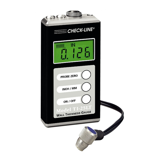
- Page 2 8.0 M (MSDA) 1.0 I ATERIAL AFETY HEET NTRODUCTION Section 1— Product Identification ® The CHECK•LINE TI-25LT Ultrasonic Thickness Gauge accurately mea- Product Name: TI-25M Generic Name: Ultrasonic Couplant sures the thickness of steel. This gauge uses the “pulse-echo” principle of Manufacturer: Electromatic Equpt.
-
Page 3: Specifications
7.0 S PECIFICATIONS 3.0 O VERVIEW AUGE Range* 0.040–6.00" (1.00–150.0 mm) 3.1 Gauge Other ranges available with optional probes. Probe Zero Test Plate and Resolution 0.004" (0.01 mm) Probe Battery Compartment Cover Receptacles Display 4 1⁄ 2 -Digit, 0.5" Backlit LCD Velocity Range .0787–.3937 in/µs... - Page 4 2. Remove the probe from the hot surface immediately after a “stable” 3.2 Contents Of Kit reading is displayed. Even though the High Temperature Probes are The TI-25LT is supplied as a complete kit with the following: constructed using materials which can withstand high temperatures, a.
- Page 5 6.2 Measurements Of Pipes Or Cylindrical Parts 3.4 Keypad When using the TI-25LT to measure the Perpendicular The TI-25LT is supplied with a membrane keypad wall thickness of a pipe, the orientation mounted on the front of the instrument body. PROBE ZERO of the probe is very important to obtain accurate readings.
-
Page 6: Measuring Procedure
6.0 MEASURING PROCEDURE The eight vertical bars shown form the Stability INMM/µs After performing the Probe Zero operation, the gauge is ready to take wall Indicator. When the TI-25LT is idle, only the thickness measurements. 1.8.8.8.8 left-most bar and underline will be illuminated. 1. -
Page 7: Quick Start Instructions - Steel Thickness
5.0 QUICK START INSTRUCTIONS — STEEL THICKNESS 3.7 Probe Connector Receptacle 1. Turn on the power by pressing the ON/OFF key. Located on the top edge of the TI-25LT housing are the receptacles for the probe and the probe zero plate. 2. -
Page 8: Getting Started
4.0 G 4.4 Changing Units — inches to mm ETTING TARTED To change the measuring units from inch (factory setting) to mm, press the 4.1 Connecting The Probe INCH/MM key. Each time the key is pressed, the units will change. Grasp the connector located at the end of the probe cable and carefully 4.5 Checking Calibration With The Probe Zero Plate insert the connector plugs into the receptacle located at the top edge of the... - Page 9 ® CHECK LINE • BY ELECTROMATIC TI-25LT LTRASONIC HICKNESS AUGE Distributed by: ABQ Industrial LP USA Tel: +1 (281) 516-9292 / (888) 275-5772 eFax: +1 (866) 234-0451 Operating Instructions Web: https://www.abqindustrial.net E-mail: info@abqindustrial.net...
Need help?
Do you have a question about the ULTRASONIC TI-25LT and is the answer not in the manual?
Questions and answers