Table of Contents
Advertisement
Quick Links
MH27877
ANSI Z21.13b-2012
Low-Press Boiler
INSTALLER:
PLEASE HANG THIS INSTRUCTION MANUAL AND ACCESSORY INSTRUCTIONS VISIBLY
NEXT TO THE BOILER USING THE SUPPLIED POUCH.
CONSUMER: PLEASE RETAIN THIS INSTRUCTION MANUAL AND ACCESSORY INSTRUCTIONS FOR
FUTURE REFERENCE.
This product meets the
Energy Star
for efficiency.
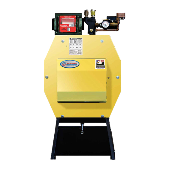
Resolute Boiler
INSTALLATION & SERVICE MANUAL
GAS HEAT EDITION
MANUFACTURED BY:
ENERGY KINETICS, INC.
51 Molasses Hill Road
Lebanon, NJ 08833
(908) 735-2066
www.energykinetics.com
Resolute Gas Heat –Sixth Edition – September, 2018
®
guidelines
®
or
www.system2000.com
ASME certified by EKI.
Certificate plate is under the
jacket on the steel vessel.
Advertisement
Table of Contents

Related Manuals for ENERGY KINETICS Resolute Boiler


Summary of Contents for ENERGY KINETICS Resolute Boiler
- Page 1 This product meets the ® Energy Star guidelines for efficiency. Resolute Boiler ® INSTALLATION & SERVICE MANUAL GAS HEAT EDITION ASME certified by EKI. MH27877 Certificate plate is under the MANUFACTURED BY: jacket on the steel vessel. ANSI Z21.13b-2012 ENERGY KINETICS, INC.
-
Page 3: Please Read This First
Please Read This First Special Attention Flags Please pay particular attention to the following flags when you see them throughout this manual. DANGER: Notifies you of hazards that WILL cause severe personal injury, death or substantial property damage. WARNING: Notifies you of hazards that CAN cause severe personal injury, death or substantial property damage. CAUTION: Notifies you of hazards that WILL or CAN cause minor personal injury or property damage. - Page 4 WARNING: Have the burner/boiler started up and serviced at least once annually by a qualified service technician. Professional care is necessary to properly service your equipment and verify it is operating reliably. Failure to properly maintain the equipment could result in severe personal injury, death or substantial property damage.
- Page 5 FOR YOUR SAFETY READ BEFORE OPERATING If you do not follow these instructions exactly, a fire or explosion may result WARNING: causing property damage, personal injury or loss of life. This burner does not have a pilot. It is Use only your hand to turn the gas control equipped with an ignition device which knob.
-
Page 6: Record Of Installation
RECORD OF INSTALLATION INSTALLER NAME: INSTALLER ADDRESS: INSTALLER CITY, STATE: DATE INSTALLED: NOTES: All installations must be made in accordance with all State and Local Codes, which may differ from this manual and in accordance with the following Codes, as applicable: National Fuel Gas Code, ANSI Z223.1/NFPA 54: Installation Codes, CAN/CGA B149 National Electrical Code, ANSI/NFPA 70... -
Page 7: Table Of Contents
TABLE OF CONTENTS Page Topic Page Topic Please Read This First Install Digital Manager Record of Installation Digital Manager Option Switch Settings Table of Contents Expanded Digital Manager Installation SYSTEM 2000 Boiler - Principle of 10 & 15 Zone Manager Installation Operation Instructions Digital Manager - Principle of Operation... -
Page 8: System 2000 Boiler - Principle Of Operation
The RESOLUTE Boiler is designed with a hinged front cover that allows access to the inside of the boiler for inspection and cleaning. All access for service is from the front, so the RESOLUTE Boiler can be placed directly against a wall or into a closet. -
Page 9: Receiving And Unpacking
5. ANOTHER CALL FOR HEAT: If another zone calls for heat while the burner is already running and the return temperature is above 150 F, the zone output will turn on, immediately supplying heat to the zone. 6. MONITOR RETURN TEMPERATURE: The Manager continually senses the return temperature and will turn off the zone outputs if the return temperature drops below 130 F. -
Page 10: Clearance For Cleaning And Service
The Resolute is manufactured with the BACK of the boiler higher than the front to assist in air removal. The front door of the Resolute boiler swings down and allows full access to the flue passageways for cleaning. Do not run any gas piping or water piping in front of the front door that would prevent the front door from fully opening. -
Page 11: Combustion Air
The Smart Vent with Dilution Air System is a complete vent system that has been specifically designed for use with Energy Kinetics’ Resolute boiler. It uses a standard EK1 forced draft inducer fan and requires outside air for combustion air. Each part of this system works together and must be installed properly to work correctly. -
Page 12: Gas Burner Settings
Carlin burners has a smooth interior. If the amulet is a tight fit on the burner head, then slightly moisten inside the amulet with water. Place a 3/8" bead of retort cement onto the burner head at the flange to air tube joint, and slide the (moistened) amulet over the burner head and against the flange. -
Page 13: General Assembly
1-1/4 inches 200 feet GENERAL ASSEMBLY Assembly of various packaged units is illustrated throughout this manual. The use of non-Energy Kinetics supplied pump, controls and accessories should follow good practices. The diagrams and locations presented in the manual are recommended. - Page 14 Air Inlet Return Supply Figure 2B Boiler Feed Boiler Water Return Use Energy Kinetics Smart Thread Sealant P/N 10-0620 Typical Flow Schematic Supply Energy Converter Figure 2B indicates a typical flow schematic for boiler water feeding multiple zones. Resolute Gas Heat – Fifth Edition – October 2015...
-
Page 15: Zone Control
8-Way Boiler Treatment per 30 gallons system water. 8-Way Boiler Treatment is recommended to treat water up to medium hardness. Call Energy Kinetics for more details about boiler water treatment and about hard water conditions. -
Page 16: Winterizing
30% by volume mixture of antifreeze in water. Call Energy Kinetics for assistance in calculating how much anti-freeze to add to system. WINTERIZING NOTICE: If the SYSTEM 2000 Boiler may be exposed to freezing temperatures, such as a vacation home shut down for the winter, then anti-freeze should be added to the boiler water. -
Page 17: Line Voltage Wiring Diagram
LINE VOLTAGE WIRING DIAGRAMS All wiring installations in: The United States must comply with the NEC, and any local codes. Canada must be done in accordance with the Figure 3A Resolute Canadian Electric Code, Part I. Figure 3B Resolute Resolute Gas Heat – Fifth Edition – October 2015... -
Page 18: Low Voltage Wiring And Diagram
Set thermostat heat anticipators to 0.1 amps (or "gas" if gas/electric option). Call Energy Kinetics to request alternate low voltage wiring diagrams to handle special situations such as air handler wiring, heat pump wiring, isolation relays for thermostats, and isolation relays for heat motors or circulators, etc. -
Page 19: Digital Manager Option Switch Settings
DIGITAL MANAGER OPTION SWITCH SETTINGS Located on bottom of Digital Manager.) Figure 4B Option Function Description Switch ON = DOWN OFF = UP Low Return Temp. ON = 130 / 150 F. (Gas) OFF = 120 /140 F. (Oil) Inducer/Chimney ON = Inducer Venting OFF = Chimney Venting ON = stop purge when Boiler Return... -
Page 20: 10 & 15 Zone Manager Installation Instructions
EXPANDED DIGITAL MANAGER ZONE VALVE 9 10 ZONE MANAGER Figure 4C THERMOSTAT ZONE 9 SYSTEM 2000 THERMOSTAT HEATING ZONE 8 ZONE VALVE 8 SYSTEM 2000 ZONE 7 ZONE VALVE 7 SYSTEM 2000 ZONE 6 ZONE VALVE 6 15 ZONE MANAGER SYSTEM 2000 ZONE 5 ZONE VALVE 5... -
Page 21: Security System Interface Wiring
Figure 4B. NOTICE: Home security systems may require an “abort delay” of one second to avoid a transient signal on Manager power-up. If an abort delay is not available, use Energy Kinetics System Monitor (provided separately part # 10-0168). -
Page 22: Start Up Procedure
START UP PROCEDURE Turn on system supply switch and burner supply switch. The Digital Manager lights should come on briefly, the circulator relay should close briefly, and then the Digital Manager will show a red light next to 'power' and yellow lights on the left side if any thermostats are calling. -
Page 23: Gas Burner Operation
GAS BURNER OPERATION NOTICE: For reliable operation, set Air-Fuel mixture conservatively based on installation conditions. Carbon dioxide, Oxygen, and Carbon Monoxide readings should be taken through 1/4" test port in front jacket opening just to right of burner (see FIG. 5A). Sample tube must extend at least six (6) inches into front cover to obtain accurate readings. A test port is provided for the flue box (see FIG. -
Page 24: Installation Check Off Procedure
Installation Check Off Procedure – Gas Fired 90+ Resolute Boiler Check Off: GAS BURNER Gas orifice nipple - Correct orifice size and properly tightened Spark Electrode Position – open the front door of boiler to inspect Flame Sense Rod Position – open the front door of boiler to inspect... -
Page 25: Digital Manager Operation
DIGITAL MANAGER OPERATION WARNING: Do Not Jump! If you apply 24VAC to any digital sensor lead with the sensor connected to the Manager, you will burn out both the sensor and the Manager in less than a second. NOTE: The Manager cannot lockout the primary control on the burner. -
Page 26: Digital Energy Manager Check
Digital Energy Manager Check Troubleshooting The burner will not run unless there is a call for heat (thermostat call) or a call for domestic hot water (tank thermostat). Note: Do NOT Jumper Connections or Apply Voltage to Test the Manager. Follow these simple steps: Look at the Manager See what it is telling you is supposed to be happening. -
Page 27: Additional Manager Tests
1, 2, and 3. If problem persists, call technical support or replace manager. Note malfunction on warranty tag and return manager to Energy Kinetics. If problem goes away, there is a problem with the output wiring – check all wiring, re-connect quick connector and repeat steps 1, 2 and 3 until problem is resolved. -
Page 28: Digital Manager Sensor Testing
If resistance is greater than 3 ohms after 3 seconds of operation, B1-B2 contact is bad. Solution: Replace manager. Note: For 140F light flashing with a good B1-B2 manager relay (step 3 above), see “Trouble Shooting with the Digital Manager”. DIGITAL MANAGER SENSOR TESTING The temperature sensor in the return line allows better boiler control, and virtually eliminates condensation caused by cold returns. -
Page 29: Troubleshooting With Digital Manager
F and zone will get heat on call. IF A PLUG-IN RELAY FAILS: Replace with spare relay. If spare is not available, temporarily install a relay with 24VAC coil and 120VAC contacts. Contact Energy Kinetics for connection details. Resolute Gas Heat – Sixth Edition – September, 2018... -
Page 30: Diagnostics With The Digital Manager
DIAGNOSTICS WITH THE DIGITAL MANAGER Manager Lights Temperature Description Diagnosis Preheat cycle – zones will open when boiler (1) Normal Operation return is above 150 F (140 F if option switch 1 is off). Return temperature dropped during call. Thermostat calling ... -
Page 31: Annual Tune Up & Inspection
ANNUAL TUNE UP & INSPECTION Please refer to installation manual and burner manual for complete details and for burners other than EZ-Gas. Step 1 Initial Test (Draft Loss & CO Air box cover must be in place before testing 1. Remove 1/8” brass plug from the “over fire” test port (2) next to the burner and the flue box (1) next to the puff switch. - Page 32 Annual Tune Up & Inspection Step 7 Close Front Cover, Tighten Rear Cover Install (4) upper nuts and washers. Tighten nuts (6) uniformly. Check and tighten (6) rear cover nuts. Check Flue Pipe. Step 8 Check Zone Valves Open/Close zone valves several times to see that they move freely. Step 9 Backflush Plate Heat Exchanger 1.
-
Page 33: Amulet Replacement
The combustion chamber is of high quality material and will normally not need to be replaced. A replacement chamber, if required, is available from Energy Kinetics. The proper part number for the Resolute chamber must be specified when ordering. For interim operation, the unit may be run without a combustion chamber if necessary. Ensure that the burner head is protected by the amulet, wet pack or a similar material. - Page 34 EXPLODED VIEW OF BOILER ITEM PART NO. DESCRIPTION 10-0710 Combustion Chamber 10-1077 Energy Converter, Resolute 10-0712 Front Chamber Liner 10-0713 Rear Chamber Liner (PacMan) 10-0715 Front Insulation Board 2” 10-0720 Front Cover w/Studs 10-0721 Left Jacket 10-0722 Right Jacket 10-0723 Top Jacket 10-0716 Rear Insulation Board 2”...
-
Page 35: Commonwealth Of Massachusetts
Commonwealth of Massachusetts Approval No. C1-0713-539. This Energy Kinetics gas fired hot water boiler has been approved by the Massachusetts Board of Plumbers and Gas Fitters. When an Energy Kinetics gas fired hot water boiler is installed in the Commonwealth of Massachusetts, the following requirements must be met. - Page 36 This page intentionally left blank. Resolute Gas Heat – Sixth Edition – September, 2018...
- Page 37 This page intentionally left blank. Resolute Gas Heat – Sixth Edition – September, 2018...
- Page 38 This page intentionally left blank. Resolute Gas Heat – Sixth Edition – September, 2018...
- Page 39 This page intentionally left blank. Resolute Gas Heat – Sixth Edition – September, 2018...
- Page 40 This page intentionally left blank. Resolute Gas Heat – Sixth Edition – September, 2018...
- Page 41 ADDITIONAL COMPONENT LIMITED WARRANTIES 1. Energy Kinetics warrants that its Digital Manager is free from defects in material and workmanship for a period of five years from the date of installation. The warranty is extended to the End User for the lifetime of the unit by a manufacturer sponsored rebuild program offered at nominal cost.
- Page 42 If within 30 days of the discovery, this action does not produce a prompt response, notify Energy Kinetics, Inc. 51 Molasses Hill Road, Lebanon, NJ 08833, in writing with details to support the warranty claim.
Need help?
Do you have a question about the Resolute Boiler and is the answer not in the manual?
Questions and answers