Table of Contents
Advertisement
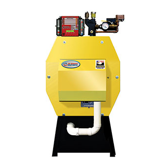
90+RESOLUTE
.
MH28303
UL 726;
CAN/CSA-B140.7-05
CAN/CSA-B140.0-03
CAN/CSA-B139-M91
Low-Press Boiler
INSTALLER:
HOMEOWNER/USER: READ AND SAVE THIS INSTRUCTION MANUAL AND ACCESSORY INSTRUCTIONS
Resolute Oil Heat – PN 10-2025 – July 2018
OWNER AND INSTALLATION MANUAL
OILHEAT EDITION
Manufactured By:
Energy Kinetics, Inc.
51 Molasses Hill Road
Lebanon, NJ 08833
www.energykinetics.com
HANG THIS INSTRUCTION MANUAL AND ACCESSORY INSTRUCTIONS VISIBLY
NEXT TO THE BOILER USING THE SUPPLIED POUCH.
FOR FUTURE REFERENCE.
UL Energy Verified, your
trusted alternative to
AFUE industry listings.
National Board
Listed
BOILER
TM
(908) 735-2066
ASME certified by EKI.
Certificate plate is under
the jacket on the steel
vessel.
Advertisement
Table of Contents

Subscribe to Our Youtube Channel
Related Manuals for ENERGY KINETICS 90+RESOLUTE BOILER


Summary of Contents for ENERGY KINETICS 90+RESOLUTE BOILER
- Page 1 National Board Listed 90+RESOLUTE BOILER OWNER AND INSTALLATION MANUAL OILHEAT EDITION MH28303 Manufactured By: UL 726; Energy Kinetics, Inc. CAN/CSA-B140.7-05 CAN/CSA-B140.0-03 51 Molasses Hill Road ASME certified by EKI. CAN/CSA-B139-M91 Lebanon, NJ 08833 Certificate plate is under Low-Press Boiler (908) 735-2066 the jacket on the steel www.energykinetics.com...
-
Page 2: Please Read This First
Please Read This First….. Special Attention Flags Please pay particular attention to the following flags when you see them throughout this manual. DANGER: Notifies you of hazards that WILL cause severe personal injury, death or substantial property damage. WARNING: Notifies you of hazards that CAN cause severe personal injury, death or substantial property damage. CAUTION: Notifies you of hazards that WILL or CAN cause minor personal injury or property damage. -
Page 3: Table Of Contents
TABLE OF CONTENTS Page Topic Page Topic Please read this first Install Energy Manager Table of Contents Five Zone Display Manager Homeowner/User Note How to Use Self-Guided On-Screen Prompts to Edit Options Record of Installation Dip Switch Settings SYSTEM 2000 Boiler - Principle of Operation Display Manager Option Menu Descriptions Energy Manager - Principle of Operation Expanded Energy Manager... -
Page 4: Homeowner/User Note
HOMEOWNER/USER NOTE: EMERGENCY SHUT DOWN INSTRUCTIONS: Turn power off to boiler by switching the “Oil Burner Emergency Switch” (typically located at the top of basement stairway or at boiler room entrance) to the OFF position. If unable to locate the “Oil Burner Emergency Switch” then switch the “System Emergency Switch”... -
Page 5: Record Of Installation
SCOPE This manual covers the Energy Kinetics System 2000 Resolute Boiler. The boiler is designed and equipped and has been tested to generate hot water in a low pressure closed loop system. The boiler is a major component of a closed loop system that can be used as a heat source for hydronic, radiant, domestic hot water, spa, and/or pool heating systems. -
Page 6: System 2000 Boiler - Principle Of Operation
This operation and maintenance information has been prepared so that you may better understand and use your Energy Kinetics Resolute Boiler and Heating System. -
Page 7: Receiving And Unpacking
6. MONITOR RETURN TEMPERATURE: The Manager continually senses the return temperature and will turn off the zone outputs if the return temperature drops below 120 F (130 F if Option Switch #1 is ON). With the zone outputs closed, the boiler water will quickly reheat and once the return temperature reaches 140 F (150 F if Option Switch #1 is ON), then the Manager will reopen the zone valves. -
Page 8: Smart Vent System
The Smart Vent with Dilution Air System is a complete vent system that has been specifically designed for use with Energy Kinetics’ Resolute boiler. It uses a standard EK1 forced draft inducer fan and requires outside air for combustion air. Each part of this system works together and must be installed properly to work correctly. -
Page 9: Fuel Systems
Resolute boilers must be equipped with a fuel filter and a flexible fuel line. Call Energy Kinetics to obtain optional UL Listed fuel filter and optional UL Listed flexible fuel line. The flexible fuel line allows the door to open without disconnecting the fuel supply. -
Page 10: General Assembly
GENERAL ASSEMBLY Assembly of various packaged units is illustrated throughout this manual. The use of non-Energy Kinetics supplied pump, controls and accessories should follow good practices. The diagrams and locations presented in the manual are recommended. -
Page 11: Piping
Supply and return connections are 1”NPT on the Resolute. Call Energy Kinetics to obtain piping and wiring instructions for alternate applications, such as hydronic heating, radiant heating, domestic hot water, swimming pool heating, multiple boilers, injection loops, etc. -
Page 12: Zone Control
ZONE CONTROL BY VALVE: The SYSTEM 2000 Boiler is designed to provide multi-zone control of the heating system and optionally can supply domestic hot water. Energy Kinetics recommends and supplies two wire, full port, 24-volt zone valves for control of each heating zone. A system with a single heating zone still requires a zone valve to provide control for preheat of unit and to maintain minimum temperature during operation. -
Page 13: Winterizing
Propylene Glycol in water will provide the following freeze protection: 30% down to +8F, 40% to -8F, 50% to -27F. Energy Kinetics recommends using 30% anti-freeze to obtain the best boiler performance. Use over 30% anti-freeze only if lower temperature freeze protection is mandatory. -
Page 14: Electrical Connection - Line Voltage
Set thermostat heat anticipators to 0.1 amps or Hydronic option. Call Energy Kinetics to request alternate low voltage wiring diagrams to handle special situations such as air handler wiring, heat pump wiring, isolation relays for thermostats, and isolation relays for heat motor style zone valves or circulators, etc. -
Page 15: Five Zone Display Manager
Five Zone Display Manager The Display Manager is an Energy Manager that is equipped with an LCD display, and four pushbutton keys. With the exception of the Fuel Type (oil/gas) and Venting (chimney/inducer) options, all setup options are selected through option screens via the display and keys. The Fuel Type and Venting options can be viewed, but not set, in the option screens. -
Page 16: Dip Switch Settings
Dip Switch Settings Set dip switches for Fuel type: Oil or Gas and Vent type: Chimney or Inducer INSTALLATION TIPS Dip Switches “OFF” Display Managers are shipped with both dip switches “OFF” (set for an oil Bottom edge of Energy Manager NOTE: “ON”... -
Page 17: Expanded Energy Manager
EXPANDED ENERGY MANAGER ZONE OUTPUTS ZONE INPUTS 15 Zone Manager 24VAC (THERMOSTATS) (ZONE VALVES OR Figure 4C ZONE CIRC RELAYS) ZONE 14 ZONE 14 ZONE 13 ZONE 13 ZONE 12 ZONE 12 ZONE 11 ZONE 11 ZONE 10 ZONE 10 ZONE 9 ZONE 9 ZONE 8... -
Page 18: Hydronic Control Settings
‘Hot’, pointer points to 6 pm. Energy Kinetics PN: 10-0414 Water Tank (On Tank) (To suit individual installation) For legacy controls, contact Energy Kinetics Factory Setting PREPARE FOR START UP DANGER: MAKE CERTAIN THE FOLLOWING REQUIREMENTS HAVE BEEN SATISFIED BEFORE START UP: 1. -
Page 19: Oil Burner Operation
BOILER OPERATION AND SAFETY CHECKS Check for proper boiler operation and proper safety operation. Correct any deficiency. DANGER: Verify proper operation of high limit aquastat. a. Remove all heat and hot water calls (No input lights on left side of manager). b. - Page 20 Energy Manager Operation WARNING: Do Not Jump! If you apply 24VAC to any Energy sensor lead with the sensor connected to the Manager, you will burn out both the sensor and the Manager in less than a second. NOTE: The Manager cannot lockout the primary control on the burner.
- Page 21 Energy Manager Check Troubleshooting The burner will not run unless there is a call for heat (thermostat call) or a call for domestic hot water (tank aquastat). Note: Do NOT Jumper Connections or Apply Voltage to Test the Manager. Follow these simple steps: Look at the Manager See what it is telling you is supposed to be happening.
- Page 22 1, 2, and 3. If problem persists, call technical support or replace manager. Note malfunction on warranty tag and return manager to Energy Kinetics. If problem goes away, there is a problem with the output wiring –...
-
Page 23: Additional Tests
Additional Manager Tests Perform the following tests ONLY if you have any of the following: Case 1) Zones heating intermittently Case 2) E140 or E150 displayed WITHOUT a burner lockout Case 3) E100 or E190 displayed If you have a burner lockout, troubleshoot as any conventional burner lockout. Case 1: Zones heating intermittently Step 1: Have all connected thermostats including hot water aquastat call continuously for at least 10 minutes. -
Page 24: Display Manager Return Sensor Testing
Display Manager Return Sensor (Thermistor) Testing The temperature sensor in the return line allows better boiler control, and virtually eliminates condensation caused by cold returns. The temperature sensor is a thermistor sealed with epoxy inside a stainless steel well. The thermistor communicates continuously with the Manager thousands of times a minute. -
Page 25: Troubleshooting With Energy Manager
TROUBLESHOOTING with the ENERGY MANAGER Display Manager Error Codes and Faults An error code on the display indicates that Display Manager has detected a problem. E100: Temperature sensor is not working properly. This indicates that the Manager is in service board mode. Circulator and inducer run constantly, burner runs off the high limit aquastat. -
Page 26: Operation Without The Energy Manager
F and zone will get heat on call. IF A PLUG-IN RELAY FAILS: Replace with spare relay. If spare is not available, temporarily install a relay with 24VAC coil and 120VAC contacts. Contact Energy Kinetics for connection details. EMERGENCY HEAT WITHOUT ENERGY MANAGER or RELAY BOARD (Temporary Operation Only –... - Page 27 ANNUAL TUNE UP & INSPECTION Step 1 Initial Test (Draft Loss & CO Make sure air box cover is in place before testing 1. Remove 1/8” brass plug from the “over fire” test port (2) next to the burner and the flue box (1) next to the puff switch.
-
Page 28: Annual Tune Up & Inspection
ANNUAL TUNE UP & INSPECTION Step 7 Check Burner 1. Check end cone through air tube opening with drawer assembly removed. 2. Check Fan/Air Inlet for dirt or lint. 3. Install drawer assembly and check ignitor. 4. Check Filter condition. Replace annually or if vacuum exceeds 7” for single pipe systems. -
Page 29: Replacement Parts
The combustion chamber is of high quality refractory ceramic fiber material and will normally not need to be replaced. A replacement chamber, if required, is available from Energy Kinetics. Figure. 6 The proper part number for the Resolute chamber must be specified when ordering. -
Page 30: Replacement Parts Ordering
Replacement Parts ITEM PART NO. DESCRIPTION 10-0710 Combustion Chamber 10-1077 Energy Converter, Resolute 10-0712 Front Chamber Liner 10-0713 Rear Chamber Liner (PacMan) 10-0715 Front Insulation Board 2” 10-0720 Front Cover w/Studs 10-0721 Left Jacket 10-0722 Right Jacket 10-0723 Top Jacket 10-0716 Rear Insulation Board 2”... -
Page 31: Limited Lifetime Warranty
In the event that such pressure vessel is found to be defective in material or workmanship during the first ten years, Energy Kinetics will repair or replace the pressure vessel at its option and include a labor allowance per the published schedule. - Page 32 The End User is required to make available for inspection by Energy Kinetics or its representative, the parts claimed to be defective and, if requested by Energy Kinetics, to ship said parts prepaid to Energy Kinetics at the above address for inspection or repair. In addition, the homeowner agrees to make all reasonable efforts to settle any disagreement arising in connection with this claim before resorting to legal remedies in courts.
Need help?
Do you have a question about the 90+RESOLUTE BOILER and is the answer not in the manual?
Questions and answers