
Subscribe to Our Youtube Channel
Related Manuals for LEYBOLD Ruvac WH 700


Summary of Contents for LEYBOLD Ruvac WH 700
- Page 1 RUVAC WH 700 Roots booster with synthetic oil or PFPE-filling Installation and Operating Instructions GA03122_002_C0 Part Numbers 155 202 – 155 209V 167 186V...
-
Page 2: Table Of Contents
Transport and Storing Installation Placement Connection of the Flanges Filling in of the Lubricant Conforming Use 3.4.1 Non-conforming Use Connecting the Cooling Water 3.5.1 Water Quality Electrical Connection 3.6.1 Checking the Direction of Rotation GA03122_002_C0 - 10/2016 - © Leybold... - Page 3 Safety Information Changing the Lubricant Cleaning the Inlet Screen Cleaning the Pump Chamber Service at Leybold Maintenance Intervals Troubleshooting Wearing and Original Spare Parts Waste Disposal These installation and operating instructions are the original instructions. GA03122_002_C0 - 10/2016 - © Leybold...
- Page 4 Operating Instructions and follow the information so as to ensure optimum and safe working right from the start The Leybold RUVAC WH has been designed for safe and efficient operation when used properly and in accordance with these Operating Instructions. It is...
-
Page 5: Important Safety Information
The lifting eyes of the RUVAC must never be used to lift any pump combinations (Roots pump + backing pump). Exceptions are allowed only after approval by Leybold. Use a crane to secure the pump at the lifting eyes provided until a firm link has been established with the backing pump or a corresponding fixture. -
Page 6: Electrical Hazards
The pumps must only be operated at the allowed speeds. In particular when using frequency converters not approved by Leybold you must ensure an effective protection against overspeeding. -
Page 7: Thermal Hazards
Since not all application related hazards for vacuum systems can be described in detail in these Operating Instructions, Leybold has availa- ble a separate document (Safety Booklet) in which the hazards and general safety concepts for design, operation and maintenance of vac- uum systems are explained. - Page 8 For this see Section 5.5 Service at Leybold. Leybold is not in a position to perform servicing (repairs) and waste disposal of radioactively contaminated pumps. Both needs to be ensured from the side of the user.
-
Page 9: Ignition Risk
All relevant safety standards and regulations must be observed. The standard version of the RUVAC is not suited for operation in explosion hazard areas. Contact us before planning to use the pump under such circumstances. GA03122_002_C0 - 10/2016 - © Leybold... -
Page 10: Noise Hazard
The pump is not suited for applications that produce abrasive or adhe- sive substances or condensable vapours which leave adhesive or high viscosity deposits. Please contact Leybold in order to select proper separators, for example. Do not allow the ingestion of any objects (screws, welding beads, nuts, washers, pieces of wire, etc.) through the intake port of the... - Page 11 The location of the RUVAC should be such that all controls are easily accessible. In order to ensure an adequate oil supply, the location at which the pump (including its accessories) is operated should be such that angles over > 5° from the vertical are avoided. GA03122_002_C0 - 10/2016 - © Leybold...
-
Page 12: Description
PTC temperature resistors have been integrated in the stator coil of the motors. At the RUVAC WH 700, Part No. 167186V, the frequency converter is mount- ed to the pump with a matching housing. GA03122_002_C0 - 10/2016 - © Leybold... -
Page 13: Standard Specification
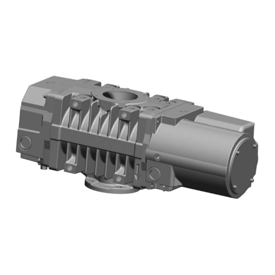
Fig. 1.2 RUVAC WH 700, Part No. 167186V Lubricants The RUVAC WH 700 pumps are prepared for use with synthetic oil or for use with PFPE special lubricant (perfluoropolyether). Only the pumps with PFPE lubricant may be used to pump highly aggressive and hazardous gases. -
Page 14: Technical Data
Lubricant gear side motor side Connection flange DN ISO-K Inlet Outlet Weight Dimension (W x B x H) 709 x 265 x 270 Noise level dB(A) < 56 < 56 < 60 < 60 GA03122_002_C0 - 10/2016 - © Leybold... - Page 15 3) Higher pressure differences are possible. Please contact Leybold 4) Gas temperatures over 40 °C can result in a reduction of the pressure difference values; please consult Leybold on this 5) The optional frequency converter automatically reduces the rotational speed of the rotors so as to compensate for overloads.
- Page 16 Description 200V FC Motor 10.5 400V FC Motor Frequency [Hz] Frequenz [Hz] Fig. 1.3 Motor current limits for overload protection for the WH 700 M8x8 Fig. 1.4 Dimensional drawing GA03122_002_C0 - 10/2016 - © Leybold...
-
Page 17: Ordering Information
Description incl. mains filter 155 217V CIMR-VC 4A0011BAA WH 700 400 V 4 kW 140 x 128 x 190 155 218V CIMR-VC 2A0020BAA WH 700 200 V 4 kW 140 x 128 x 190 GA03122_002_C0 - 10/2016 - © Leybold... -
Page 18: Transport And Storing
When the pump is removed from the shipping container it has to be secured with suitable lifting equipment until it is safely joined to a vacuum flange or a rack that is stable enough to support the weight of the pump. GA03122_002_C0 - 10/2016 - © Leybold... - Page 19 Connect the pump to oper- ate it briefly and then decommission it as described in the following sections. Refer to the frequency converter Operating Instructions when a frequency converter was longer than 2 years on stock. GA03122_002_C0 - 10/2016 - © Leybold...
-
Page 20: Installation
Moreover, the pump attains its thermal operating limit faster. Secure the pump. Four bores in the bottom of the pump casing (M8) are pro- vided for this purpose. GA03122_002_C0 - 10/2016 - © Leybold... -
Page 21: Connection Of The Flanges
Even with clean vacuum processes, contaminants from the system may enter upon initial start-up. Depending on the operating conditions, the inlet screen may reduce the pumping speed of the pump. GA03122_002_C0 - 10/2016 - © Leybold... -
Page 22: Filling In Of The Lubricant
1.2 bar. Accessories which have not been specified by Leybold may only be used after approval by Leybold. GA03122_002_C0 - 10/2016 - © Leybold... -
Page 23: Non-Conforming Use
When stored in a humid atmosphere corrosion can occur. Conversions, manipulations and maintenance work by persons not author- ■ ised by Leybold. The non-conforming utilisation of pump and accessories may result in WARNING severe injury or damage to the components. GA03122_002_C0 - 10/2016 - © Leybold... -
Page 24: Connecting The Cooling Water
When connecting the cooling water by way of a “parallel connection” the NOTICE supply and return lines must not be confused. Ensure that the cooling water lines are leak tight. Water leaks can damage the electronics of the pump. GA03122_002_C0 - 10/2016 - © Leybold... -
Page 25: Water Quality
If there is the danger of frost, you may use a water glycol mixture of up to 30 %. DS water (softened or fully desalinated water) can be used for cooling the system, if the pH value corresponds to the range indicated above. GA03122_002_C0 - 10/2016 - © Leybold... -
Page 26: Electrical Connection
The RUVAC is suitable for operation in industrial applications only. It is not suitable for operation with mains supplies of residential areas since it could cause radio frequency interference. The connection voltage must agree with the voltage stated on the name- plate. GA03122_002_C0 - 10/2016 - © Leybold... - Page 27 - Activation with seized impeller Fig. 3.6 Circuit example for the temperature sensor Fig. 3.5 Circuit example for motor protection Y - (Star) circuit Fig. 3.7 Mains power connection (circuit diagram in the junction box) GA03122_002_C0 - 10/2016 - © Leybold...
- Page 28 The RUVAC WH 700 must be integrated in the system control arrangement so that the pump can not run-up automatically after it has been shut down by the temperature switches in the motor. This applies equally to emergency shut-down arrangements.
- Page 29 In order to protect the pump, current limits in the frequency converter as a function of the frequency must be taken into account. See diagram for 200 V and 400 V FC motor (Section 1.3, Technical Data). GA03122_002_C0 - 10/2016 - © Leybold...
- Page 30 Open: Output disabled. Closed: Normal operation. Notice: Disconnect wire jumper between HC Safety disable Safety disable input and H1 when using the safety disable input. input The wire length should not exceed 30 cm. GA03122_002_C0 - 10/2016 - © Leybold...
- Page 31 Multi function input Drive Drive Branch Branch resistor resistor 12 kOhm (+10,5 V, 20mA) 12kOhm A2 (0-10 V) Multifunction output Multi function output (photocoupler) (photocoupler) thermistor thermistor Fig. 3.11 Connection of the motor PTC GA03122_002_C0 - 10/2016 - © Leybold...
- Page 32 The potential equalisation conductor must be connected as depicted in fig. 3.12. Copper strap, for example Washer Lock washer Hexagon socket screw M8 Fig. 3.12 Establishing the potential equalisation at the pump casing GA03122_002_C0 - 10/2016 - © Leybold...
-
Page 33: Checking The Direction Of Rotation
For this, evacuate the vacuum system down to a pressure below 20 mbar with the aid of the backing pump. Then switch on the RUVAC briefly; now the pressure must drop. If the pressure increases or remains constant, the RUVAC is turning in the wrong direction. GA03122_002_C0 - 10/2016 - © Leybold... -
Page 34: Operation
Example - Pump combination: RUVAC WH 700 / Sogevac SV 100 710 m · h = ————— 100 m · h 75 mbar ————— 12 mbar 7 - 1 at the respective operating frequency for 50 Hz operation GA03122_002_C0 - 10/2016 - © Leybold... -
Page 35: Operation
Hot surfaces, risk of suffering burns. CAUTION Notice safety information 0.3. Never open the oil-fill or oil-drain plugs in the presence of a vacuum or while the pump is running. There is the danger that oil may squirt out. GA03122_002_C0 - 10/2016 - © Leybold... -
Page 36: Operation With External Frequency Converter
In case a chamber pumpdown from pressures above cut-in pressure is need- ed, either bypass the RUVAC or shut it down and allow the impellers to slow down before starting pumpdown. GA03122_002_C0 - 10/2016 - © Leybold... -
Page 37: Switching Off And Decommissioning
PFPE does not have a conserving effect. For RUVAC pumps with synthetic oil we recommend this protection measure. For transportation and storing of the pump, observe the information provided in Section 2. GA03122_002_C0 - 10/2016 - © Leybold... -
Page 38: Maintenance
Advanced repair work not described here should be left to the Leybold Service. We would like to point out that Leybold offers training cour-ses on the main- tenance, repair, and troubleshooting of RUVAC pumps. Further details are available on request. -
Page 39: Changing The Lubricant
Under normal operating conditions, change the synthetic oil after every 8,000 hours of operation. Change the synthetic oil more frequently when pumping corrosive vapours or large amounts of dust or when cycling frequently from atmospheric to work- ing pressure. GA03122_002_C0 - 10/2016 - © Leybold... - Page 40 Do not exceed a fastening torque of 3 Nm. Otherwise the thread of the pump casing could get damaged. For recycling contaminated PFPE we ask you to consult us. As PFPE we rec- ommend our LVO 400. GA03122_002_C0 - 10/2016 - © Leybold...
-
Page 41: Cleaning The Inlet Screen
They should move freely and without any resistance. Generally, the Roots pump does not need to be disassembled. If neces- sary, this should only be done by our after-sales service. GA03122_002_C0 - 10/2016 - © Leybold... -
Page 42: Service At Leybold
Maintenance Service at Leybold If you send a pump to Leybold indicate whether the pump is free of sub- stances damaging to health or whether it is contaminated. If it is contaminated also indicate the nature of the hazard. To do so, you must use a pre-printed form which we shall send to you upon request. -
Page 43: Maintenance Intervals
PFPE change not required Check cooling Quarter yearly water connections at the motor for leak tightness Clean motor fan Depending on the ambient conditions See Section 5.3 and cooling fins GA03122_002_C0 - 10/2016 - © Leybold... -
Page 44: Troubleshooting
Fix and connect pump free of tension. 3.1/3.5 Bearing or gear damage. Leybold Service, shutdown pump immediate- Pistons make contact with the casing. Leybold Service, shutdown pump immediate- Rotor is running untrue. Leybold Service, shutdown pump immediate- GA03122_002_C0 - 10/2016 - © Leybold... - Page 45 Speed is too low. Set up the correct speed. Motor stator is defective. Leybold Service Pump system has a gas leak. Detect leak and seal it off. Too much impeller play. Leybold Service. Bearing defective. Leybold Service GA03122_002_C0 - 10/2016 - © Leybold...
-
Page 46: Wearing And Original Spare Parts
Waste oil from vacuum pumps must not be mixed with other substances or materials. Waste oil from vacuum pumps (Leybold oils which are based on mineral oils) which are subject to normal wear and which are contaminated due to the influence of oxygen in the air, high temperatures or mechanical wear must be disposed of through the locally available waste oil disposal system. - Page 47 GA03122_002_C0 - 10/2016 - © Leybold...
- Page 48 Notes GA03122_002_C0 - 10/2016 - © Leybold...
- Page 49 Person to contact: Calibration: Factory-calibr. Phone : Fax: Quality test certificate DIN 55350-18-4.2.1 End user: A. Description of the Leybold product: Failure description: Material description : Catalog number: Additional parts: Serial number: Application-Tool: Application- Process: Type of oil (ForeVacuum-Pumps) : B.
- Page 50 Sales and Service Germany Great Britain America Leybold Japan Co., Ltd. Tsukuba Technical Service Center Leybold UK LTD. 1959, Kami-yokoba Leybold GmbH Tsukuba-shi, Ibaraki-shi 305-0854 Unit 9 Sales, Service, Support Center (3SC) Japan Silverglade Business Park Bonner Strasse 498 Leybold USA Inc.
Need help?
Do you have a question about the Ruvac WH 700 and is the answer not in the manual?
Questions and answers