Table of Contents
Advertisement
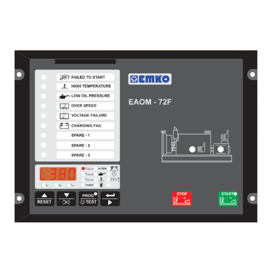
EAOM-72F
Automatic Generator Start Controller
with Metering, Flat Type
- Automatic engine start / stop
- Automatic shutdown on fault condition
- LED status and fault indication
- Alternator voltage and frequency measurement and monitoring
- Battery voltage measurement and monitoring
- Simple push-button controlled operation
- Over / under speed warning and shutdown
- Remote start / stop input
- Three user
configurable
- Three Resistive Sender Inputs
- Provides charge alternator excitation current
- Two configurable outputs
- Speed sensing from alternator frequency or magnetic pickup
- Fully programmable
- RS-232 communication port
- Standard modem communication
- Monitors
Three phase alternator voltage
Three phase current input
Alternator power
Alternator frequency
Engine speed
Oil pressure
- Controls
Engine fuel supply or stopping
Starter motor
Alarm horn
- Fail Monitoring
Alternator Voltage, Frequency
Engine Speed
Engine Temperature
Oil Pressure
inputs
Engine temperature
Fuel level
Battery voltage
Engine running time
Error indication
Program parameters
Automatic generator start and stop
Preheat
Engine Start
Charge Generator Voltage
Emergency Stop
Maintenance Due
Instruction Manual. ENG
EAOM-72F
SOFT
PC Communication Software for
Programming and Remote Monitoring
EAOM-72F
02 V02 04/21
Advertisement
Table of Contents

Related Manuals for EMKO EAOM-72F


Summary of Contents for EMKO EAOM-72F
- Page 1 EAOM-72F EAOM-72F SOFT PC Communication Software for Automatic Generator Start Controller Programming and Remote Monitoring with Metering, Flat Type - Automatic engine start / stop - Automatic shutdown on fault condition - LED status and fault indication - Alternator voltage and frequency measurement and monitoring...
- Page 2 ABOUT INSTRUCTION MANUAL Instruction manual of EAOM-72F consists of two main sections. Explanation of these sections are below. Also, there is another section which include technical specifications of the device. All titles and page numbers in instruction manual are in “...
-
Page 3: Table Of Contents
4.1 CABLE CONNECTION BETWEEN RS-232 TERMINAL OF THE DEVICE AND PC 4.2 CABLE CONNECTION BETWEEN RS-232 TERMINAL OF THE DEVICE AND MODEM 4.3 PC INTERFACE 4.3.1 TECHNICAL SPECIFICATIONS 4.3.2 INSTALLATION INSTRUCTIONS 4.3.2.1 MINIMUM SYSTEM REQUIREMENTS 4.3.3 INSTALLING EAOM-72F SOFTWARE 4.3.4 USING OF EAOM-72F COMMUNICATION SOFTWARE 4.3.5 DESCRIPTION 4.3.6 OBSERVATION WINDOW 4.3.7 OPERATOR PARAMETERS WINDOW... - Page 4 5.1.19 CURRENT TRANSFORMER RATIO 5.1.20 CONFIGURABLE INPUTS 5.1.21 CONFIGURABLE OUTPUTS 5.1.22 OIL PRESSURE SWITCH / SENDER SELECTION 5.1.23 OIL PRESSURE LOWER LIMIT 5.1.24 OIL PRESSURE ALARM CONFIGURATION 5.1.25 TEMPERATURE UPPER LIMIT 5.1.26 TEMPERATURE ALARM CONFIGURATION 5.1.27 FUEL LEVEL LOWER LIMIT 5.1.28 FUEL LEVEL ALARM CONFIGURATION 5.1.29 OPERATOR PASSWORD 5.1.30 TECHNICIAN PASSWORD...
- Page 5 EU DECLARATION OF CONFORMITY Manufacturer Company Name : Emko Elektronik A.S. Manufacturer Company Address: DOSAB, Karanfil Sokak, No:6, 16369 Bursa, Turkiye The manufacturer hereby declares that the product conforms to the following standards and conditions. Product Name Electrical control equipment for generating sets...
-
Page 6: Preface
1. PREFACE These products provide control and protection in the operation of a generator set. The units allow starting and stopping of the engine and indicates status and fault conditions. The unit monitors: Engine temperature Oil pressure Fuel level Charge generator voltage Engine speed Alternator output (voltage and frequency) Alternator current and power... -
Page 7: General Specifications
1.1 General Specifications +BATTERY POWER Selection SUPPLY MICROCONTROLLER BATTERY VOLTAGE TRANSISTOR SENSING OUTPUTS LOAD CURRENT SENSING & COMMON CONDITIONING GENERATOR VOLTAGE GEN L1 SENSING GEN L2 & ANALOG GEN L3 CONDITIONING DIGITAL CONVERTER PRES. ANALOG TEMP. INPUTS LEVEL COMMON FREQUENCY SENSING FROM GENERATOR... -
Page 8: Warranty
1.2 Warranty EMKO Elektronik warrants that the equipment delivered is free from defects in material and workmanship. This warranty is provided for a period of two years. The warranty period starts from the delivery date. This warranty is in force if duty and responsibilities which are determined in warranty document and instruction manual performs by the customer completely. -
Page 9: Installation
Carefully unpack the unit and check for damage to the unit or to the cables supplied. Retain the packing in case of future need, e.g. returning the unit for calibration. Check the contents, as follows: • One EAOM-72F unit. • Operating Manual. • Screw fixings. -
Page 10: General Description
2.1 General Description Label Pockets Terminal Connection Mounting Holes Front Panel IP65 protection NEMA 4X 2.2 Dimensions 204mm Figure 2.1 Front View 10.5 mm 26.5 mm Figure 2.2 Side View... -
Page 11: Panel Cut-Out
2.3 Panel Cut-Out R=4.5mm R=4.5mm 186 mm 196 mm 2.4 Environmental Ratings Operating Conditions Operating Temperature °C to 70°C Max. Operating Humidity : Rh (non-condensing) Altitude Up to 2000m. Forbidden Conditions: Corrosive atmosphere Explosive atmosphere Home applications (The unit is only for industrial applications) -
Page 12: Panel Mounting
2.5 Panel Mounting Before mounting the device in your panel, make sure that the cut-out is of the right size Make sure that the diameter of the holes are of the right size and coordinate of the holes are true. Check front panel gasket position Insert the device through the cut-out. -
Page 13: Removing From The Panel
2.7 Removing from the Panel Before starting to remove the unit from panel, power off the unit and the related system. RESET 1. Loosen the screws. 2. Pull the unit through the front side of the panel... -
Page 14: Electrical Wirings
3. ELECTRICAL WIRINGS 3.1 Terminal Layout and Connection Instructions Only qualified personnel and trained technicians should work on this equipment. This equipment contains internal circuits with voltage dangerous to human life. Do not open or dismantle the product enclosure. While installing the unit, battery voltage range must be controlled and appropriate battery voltage must be applied to the unit. -
Page 15: Electrical Wiring Diagram
3.2 Electrical Wiring Diagram 3.2.1 1-Phase Wiring Diagram CURRENT TRANSFORMERS GENERATOR LOAD GENERATOR VOLTAGE SOLENOID OUTPUT SWITCHED SWITCHED POSITIVE OR NEGATIVE SUPPLY POSITIVE SUPPLY TRANSISTOR OUTPUT MAX.500mA SWITCHED NEGATIVE SUPPLY Magnetic Pickup (up to 10kHz) FUSE-2 D+(W.L.) -BATTERY +BATTERY BATTERY NEGATIVE 3.2.2 3-Phase Wiring Diagram CURRENT TRANSFORMERS... - Page 16 Output to fuel relay or stop 500mA transistor output solenoid Output to start/cranking relay 500mA transistor output Z Supply to unit -Battery supply to EAOM-72F and transistor outputs common Z Supply to unit +Battery supply to EAOM-72F Input from magnetic pickup Configurable failure input-3...
- Page 17 (via external relay and +V or -V selection link) Transistor output to start relay. Controls starter motor (via external relay) 10 -V battery input. Supplies EAOM-72F and transistor outputs common. +V battery input. Supplies EAOM-72F. 12 Input from magnetic pickup. Unit can be programmed for number of teeth Input from magnetic pickup.
-
Page 18: Rs-232 Serial Interface, Programming The Device Over Pc Or Modem
4.RS-232 SERIAL INTERFACE, PROGRAMMING THE DEVICE OVER PC OR MODEM 4.1 Cable Connection Between RS-232 Terminal of the Device and PC EAOM-72F 9 pin D connector 9 pin D connector female male White Brown Green Standard communication cable 4.2 Cable Connection Between RS-232 Terminal of the Device and Modem... -
Page 19: Pc Interface
Insert the software CD into the CD-ROM drive on the PC. CD will autostart, then select EAOM- 72F Install.exe from the menu. 4.3.4 Using Of EAOM-72F Communication Software Press the windows START button icon, then select EAOM-72F SW EAOM-72F from the Þ program menu. 4.3.5 Description EAOM-72F unit communicates with the PC using RS-232 communications. -
Page 20: Observation Window
4.3.6 Observation Window In this window the values listed below can be observed. Measurement Values Failures Outputs Generator Voltage Failed to Start Start Relay Load Current Low Oil Pressure Horn Relay Engine Speed High Temperature Solenoid Relay Generator Frequency Voltage Failure Configurable Relay Output 1 &... -
Page 21: Operator Parameters Window
4.3.7 Operator Parameters Window Operator parameters can be viewed and edited. Parameters are password protected. When the operator password is entered, it is compared with operator password that is registered inside the EAOM-72F unit. 4.3.8 Technician Parameters Window All parameters can be viewed and edited in this window. Parameters are password protected. -
Page 22: Settings
4.3.9.3 Settings Communication Port Settings: With this menu, user can determine the serial port configurations of the PC. Language: Turkish or English can be selected. Verify After Download: If this selection is checked, after downloading parameters are read to check if they are the same with the downloaded parameters. 4.3.10 Entering to the Operator Parameters Window Click Operator Parameter tab. -
Page 23: Entering To The Technician Parameters Window
4.3.11 Entering to the Technician Parameters Window Click Technician Parameter tab. Enter the Technician Parameter password. If password is correct, all parameters will be viewed. 4.3.12 Entering to the Adjustment Window Click Technician Parameter tab. Enter the Technician Parameter password. If password is correct, all parameters will be viewed. -
Page 24: Load The Configuration File From Disc
'Save' button on Save Dialog Box, all parameters will be saved to the file. 4.3.15 Upload For loading parameters from EAOM-72F u nit to PC follow the steps below. If user is in operator parameters window, only operator parameters will be viewed. If user is in Technician Parameters Window, all parameters will be viewed. -
Page 25: Parameters
5. PARAMETERS The unit is extensively programmable through the front panel and via PC software. Definition of Parameter Unit Default Alternator Voltage Lower Limit Alternator Voltage Upper Limit Speed Lower Limit 30.0 75.0 47.0 Speed Upper Limit 30.0 75.0 53.0 Battery Voltage Lower Limit 24.0 Battery Voltage Upper Limit... - Page 26 Definition of Parameter Unit Default Configurable Failure Input-1 0 - Status 1 - Fire switch 2 - Only horn temporary 3 - Only horn permanent 4 - Engine stop Configurable Failure Input-2 0 - Status 1 - Fire switch 2 - Only horn temporary 3 - Only horn permanent 4 - Engine stop Configurable Failure Input-3...
- Page 27 Definition of Parameter Unit Default Configurable Output-2 0 - Alarm out 1 - Engine running 2 - Load permit 3 - Preheat 4 - Over speed 5 - Over current 6 - Low fuel level 7 - High temperature 8 - Low oil pressure 9 - Maintenance due 10 - Failed to start 11 - Over / under speed...
-
Page 28: Program Functions
5.1 Program Functions 5.1.1 Alternator Voltage P00 Alternator Voltage Lower Limit P01 Alternator Voltage Upper Limit P11 Phase Type Selection P32 Alternator Voltage Fault Control Delay A fault will be reported if the alternator output voltage goes outside the window defined by the upper and lower limits for more than the time defined as the Alternator voltage fault control delay (P32). -
Page 29: Remote Start Time Delay
counter at each service. When the engine has run for the defined number of hours, the alarm LED will flash and when the alarm display option is selected, the display will read the error message bAEr. Setting Periodic Maintenance Hour Reset (P08) to zero will disable this feature. 5.1.6 Remote Start Time Delay (P19) When the Remote Start/Stop Input is activated (starting), the engine will start after the Remote Start Time Delay (P19) period, in order to prevent unnecessary starting due to a fluctuating mains... -
Page 30: Stop Magnet Energising Time
5.1.12 Stop Magnet Energising Time (P18) This parameter sets the period for which the Stop solenoid is energised to stop the engine. It applies only where parameter Stop / Fuel Solenoid Selection (P17) is set to Stop Solenoid. See Section 5.1.11 Stop/Fuel Solenoid Selection (P17) 5.1.13 Engine Started Signals (P21) The unit must de-energise the Start solenoid to disconnect the starter motor, once the engine is running. -
Page 31: Control On Delay
(P31) defines a period during which any fault indications, except High Temperature, will be ignored by the unit. T his period begins when the EAOM-72F has detected engine starting and has cut off the drive to the starter motor. 5.1.17 Engine Cooling Time (P34) Engine Cooling Time (P34) defines the duration of the cooling-off period. -
Page 32: Oil Pressure Switch / Sender Selection
Preheat function. On starting the generator, this output is active for time period defined in Preheat Time (P10) prior to running the starter motor. Over Speed Shut-down Output. The fault will only occur after the engine has been running for the period defined in Speed Fault Control Delay (P33) and Speed Upper Limit (P03). - Page 33 5.1.29 Operator Password (P49) Use this option to change the Operator password. This password allows access to the parameters from Alternator Voltage Lower Limit (P00) to Preheat Time (P10) and Operator Password ( P49). 5.1.30 Technician Password (P50) Use this option to change the Technician password. It allows access to the all parameters from Alternator Voltage Lower Limit (P00) to Technician Password (P50).
-
Page 34: Operator Password
5.2 Changing and Saving Operator Parameter Value When button is Operation Screen Hz./RPM L12/L1N pressed, all leds and digits L23/L2N are energised, because ~ ~ ~ L31/L3N prog button is also used as POWER test button. Continue to PROG press the prog buton for 5 seconds, Operator Menu RESET TEST... - Page 35 Alternator Voltage Hz./RPM L12/L1N Lower Limit L23/L2N Parameter ~ ~ ~ L31/L3N POWER Press button for PROG accessing to the RESET TEST value Alternator Voltage Hz./RPM L12/L1N Lower Limit L23/L2N Value ~ ~ ~ L31/L3N POWER Change the PROG parameter with RESET TEST buttons...
-
Page 36: Technician Password
5.3 Changing and Saving Technician Parameter Value When button is Operation Screen Hz./RPM L12/L1N pressed, all leds and digits L23/L2N are energised, because ~ ~ ~ L31/L3N prog button is also used as POWER test button. Continue to PROG press the prog buton for 5 seconds, Operator Menu RESET TEST... - Page 37 Alternator Voltage Hz./RPM L12/L1N Lower Limit L23/L2N Parameter ~ ~ ~ L31/L3N POWER Press button for PROG accessing to the RESET TEST Value Alternator Voltage Hz./RPM L12/L1N Lower Limit L23/L2N Value ~ ~ ~ L31/L3N POWER Change the PROG parameter with RESET TEST buttons...
-
Page 38: Commissioning
After a visual inspection to ensure it is safe to proceed, connect the battery supply. Ensure that the EAOM-72F display switched on. Press the Engine Start Button (7). Check that the engine start sequence commences. The starter motor should run for the Starting Attempt Duration (P27) for the Number of Starting Attempts (P26). -
Page 39: Operation
8. OPERATION 8.1 Front Panel Description RESET Number Comment Four-digit, seven-segment LED display. This displays the selected parameter from the list alongside. Use the Display scroll button (2) to select which parameter is to be displayed, as indicated by the adjacent LEDs. The Display Scroll Button is used to step through all of the measured parameters. -
Page 40: Display Mode Indicators
8.2 Display Mode Indicators Hz./RPM L12/L1N L23/L2N ~ ~ ~ L31/L3N POWER Four-digit, seven-segment LED display. This displays the selected parameter from the list alongside. Use the button to select which parameter is to be displayed, as indicated by the adjacent LEDs. -
Page 41: Starting The Engine
EAOM - 7 8.3 Starting the Engine Press the START button on the panel or assert the Remote Start input (Pin 17). The engine should start. The sequence is as follows: • The starter motor runs • The engine starts Once the engine is running, •... -
Page 42: Fault Finding
9.1.2 High Temperature LED This LED flashes if the thermostatic switch on the engine indicates high temperature. If this fault occurs, the EAOM-72F will stop the engine without any Engine Cooling Time (P34). 9.1.3 Low Oil Pressure LED This LED flashes if the Oil Pressure Switch on the engine indicates low oil pressure while the engine is running. -
Page 43: Low Oil Pressure Alarm (Lopr)
EAOM-72F terminals. This failure is indicated with an error messages in EAOM-72F. When this failure occurs in EAOM-72F, the led with exclamation mark starts to flash and user can see the error messages with the Scroll button 9.1.13 Weak Battery Alarm Message (bAT2) - Page 44 Check switch and wiring. temperature fault after engine has started Check fuel solenoid and wiring, fuel and battery. Reset the EAOM-72F and restart the engine. Failed to start fault. Engine failed to start Check solenoid transistor output activated, after Number of Starting...
-
Page 45: Programmable Parameters
10. PROGRAMMABLE PARAMETERS The unit is extensively programmable through the front panel and via PC software. Definition of Parameter Default Unit Alternator Voltage Lower Limit Alternator Voltage Upper Limit 30.0 75.0 Speed Lower Limit 30.0 75.0 Speed Upper Limit Battery Voltage Lower Limit 24.0 Battery Voltage Upper Limit 12.0... - Page 46 Definition of Parameter Default Unit Configurable Failure Input-1 Configurable Failure Input-2 Configurable Failure Input-3 Observing Time of Configurable Failure Inputs P39.0 - For Configurable Failure Input-1 Observation Continuously Observation While Engine Running P39.1 - For Configurable Failure Input-2 Observation Continuously Observation While Engine Running P39.2 - For Configurable Failure Input-3...
-
Page 47: Specifications
11. SPECIFICATIONS Equipment Use : Electrical control equipment for generating sets Housing& Mounting : 144mmx204mmx37mm (including connectors) plastic housing for panel mounting Panel Cut-Out : 138mmx186mm Protection : NEMA4X (IP65 at front panel, IP20 at rear side) Weight : Approximately 0.7 kg Environmental Ratings : Standard, indoor at an altitude of less than 2000 meters with non-condensing humidity.
Need help?
Do you have a question about the EAOM-72F and is the answer not in the manual?
Questions and answers