
Related Manuals for SMC Networks ZSE20B


Summary of Contents for SMC Networks ZSE20B
- Page 1 No.PS※※-OMU0006-A PRODUCT NAME Digital Pressure Switch MODEL / Series / Product Number ZSE20B(F) ISE20B...
-
Page 2: Table Of Contents
Table of Contents Safety Instructions Model Indication and How to Order Summary of Product parts Definition and terminology Mounting and Installation Installation Piping Wiring Outline of Settings [Measurement mode] Pressure Setting 3 Step Setting Mode Simple Setting Mode Function Selection Mode Function selection mode Default setting F 0 Units selection function... -
Page 3: Safety Instructions
Safety Instructions These safety instructions are intended to prevent hazardous situations and/or equipment damage. These instructions indicate the level of potential hazard with the labels of "Caution", "Warning" or "Danger". They are all important notes for safety and must be followed in addition to International Standards (ISO/IEC) , and other safety regulations. - Page 4 Safety Instructions Caution 1.The product is provided for use in manufacturing industries. The product herein described is basically provided for peaceful use in manufacturing industries. If considering using the product in other industries, consult SMC beforehand and exchange specifications or a contract if necessary. If anything is unclear, contact your nearest sales branch.
- Page 5 Operator This operation manual is intended for those who have knowledge of machinery using pneumatic equipment, and have sufficient knowledge of assembly, operation and maintenance of such equipment. Only those persons are allowed to perform assembly, operation and maintenance. Read and understand this operation manual carefully before assembling, operating or providing maintenance to the product.
- Page 6 Caution ■Do not touch the terminals and connectors while the power is on. Otherwise electric shock, malfunction or damage to the product can result. ■After maintenance is complete, perform appropriate functional inspections and leak tests. Stop operation if the equipment does not function properly or there is a leakage of fluid. When leakage occurs from parts other than the piping, the product might be faulty.
- Page 7 ●Product handling Installation Tighten to the specified tightening torque. If the tightening torque is exceeded the mounting screws and brackets may be broken. If the tightening torque is insufficient, the product can be displaced and loosen the mounting screws. Do not apply excessive stress to the product when it is mounted with a panel mount. Otherwise damage to the product and disconnection from the panel mount can result.
- Page 8 Do not use in a place where the product could be splashed by oil or chemicals. If the product is to be used in an environment containing oils or chemicals such as coolant or cleaning solvent, even for a short time, it may be adversely affected (damage, malfunction, or hardening of the lead wires). Do not use in an area where surges are generated.
-
Page 9: Model Indication And How To Order
Model Indication and How to Order No.PS※※-OMU0006-A... - Page 10 ○Accessories/Part numbers If an option is required independently, order with the following part numbers. Items Part No. Remarks Bracket A ZS-46-A1 Self tapping screws: Nominal size 3 x 8L (2 pcs) Bracket B ZS-46-A2 Self tapping screws: Nominal size 3 x 8L (2 pcs) Panel mount adapter ZS-46-B Panel mount adapter +...
-
Page 11: Summary Of Product Parts
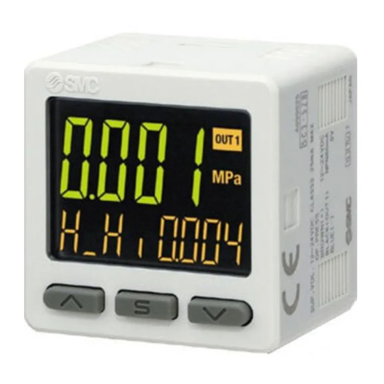
Summary of Product parts ○Names of individual parts Operation light: Displays the switch operating condition. LCD display: Displays the current status of pressure, setting mode, selected display units and error code. 4 types of display can be selected for the main display: Single color of constant red or green;... -
Page 12: Definition And Terminology
■Definition and terminology Term Definition Analog current output Refer to "Analog output (function)". Analog output function Function to output the voltage or current in proportion to the pressure. Analog voltage output Refer to "Analog output (function)". Performs pressure setting automatically by detecting the increase and decrease in pressure. - Page 13 Term Definition The code number displayed, identifying the error detected by the Error displayed self-diagnosis function of the pressure switch. Refer to "Error indication function" on page for details of the errors. Switches the switch output to ON/OFF when an error is displayed. Error output Refer to "List of output modes"...
- Page 14 Term Definition Operation light A light that turns on when the switch output is ON. Hysteresis mode, window comparator mode, Error output or Output off can be Operation mode selected. The resistance value of a component between the voltage output element and the analog voltage output.
- Page 15 Term Definition Set pressure range The pressure range that can be set for switch output. Slave Pressure switch A Pressure switch whose settings are copied to when using the copy function. Switch output Sometimes referred to as "ON-OFF output". A function to change the units in which the measured pressure value is displayed.
-
Page 16: Mounting And Installation
Mounting and Installation ■Installation ○Mounting ●Mount the optional bracket and panel mount adapter to the pressure switch. ●When the pressure switch is to be mounted in a place where water and dust splashes occur, insert a tube into the atmospheric vent port of the pressure switch. (Refer to “Tube attachment”... - Page 17 ○Mounting with panel mount adapter ●Mount part (a) to the front of the body and fix it. Then insert the body with (a) into the panel until (a) comes into contact with the panel front surface. Next, mount part (b) to the body from the rear and insert it until (b) comes into contact with the panel for fixing.
-
Page 18: Piping
■Piping ○Tightening the connection thread ●For connecting to the body (piping specification: -M5) After hand tightening, apply a spanner of the correct size to the spanner flats of the piping body, and tighten with a 1/6 to 1/4 rotation. As a reference, the tightening torque is 1 to 1.5 Nm. (When replacing the piping adapter ZS-46-N, tighten it using the same method.) ●Piping specification: -01, -N01 After hand tightening, hold the hexagonal spanner flats of the pressure port with a spanner, and tighten... - Page 19 ○Tube attachment ●When the pressure switch is used in a place where water and dust splashes may occur, insert a tube in the atmospheric vent port, and position the other end of the tube at safe position to protect the vent port from water and dust (see the figure bottom).
-
Page 20: Wiring
■Wiring ○Wiring connections ●Connections should be made with the power supply turned off. ●Use a separate route for the product wiring and any power or high voltage wiring. Otherwise, malfunction may result due to noise. ●If a commercially available switching power supply is used, be sure to ground the frame ground (FG) terminal. - Page 21 ○Internal circuit and wiring examples Z/ISE20B(F)-□-□-□-□□□ Output specification -S/-R (Analog output mode) Switch output NPN open collector output type-2 output Max. 28 V, 80 mA Residual voltage 1 V or less R: Analog output 1 to 5 V Output impedance 1 k S: Analog output 4 to 20 mA Max.
- Page 22 -V/-T (Analog output mode) Switch output PNP open collector output type-2 output Max. 80 mA Residual voltage 1 V or less T: Analog output 1 to 5 V Output impedance 1 kΩ V: Analog output 4 to 20 mA Max. load impedance Power supply voltage 12 V: 300 ...
-
Page 23: Outline Of Settings [Measurement Mode]
Outline of Settings [Measurement mode] Power is supplied. The product code is displayed for approximately 3 sec. after supplying power. : Within approximately 0.2 second after power-on, the switch starts. [Measurement mode] Detects the pressure after power is supplied, and indicates the display and switch operating status. -
Page 24: Pressure Setting
0.500 MPa [P_2] Set value of OUT2 0.500 MPa [H_1] Hysteresis of OUT1 0.050 MPa [H_2] Hysteresis of OUT2 0.050 MPa ●ZSE20B Item Default setting Item Default setting [P_1] Set value of OUT1 -50.5 kPa [P_2] Set value of OUT2 -50.5 kPa... -
Page 25: Step Setting Mode
3 Step Setting Mode 3 step setting mode In this mode, the set values can be input in just 3 steps. Use this mode if the product is to be used straight away, after changing only the set values. (The current pressure value is displayed on the main display.) <Operation>... - Page 26 The Pressure switch turns on within a set pressure range (from P1L to P1H) during window comparator mode. Set P1L, the lower limit of the switch operation, and P1H, the upper limit of the switch operation and WH1 (hysteresis) following the instructions given on page 24. (When reversed output is selected, the sub display (left) shows [n1L] and [n1H].) Please refer to the "List of output modes"...
-
Page 27: Simple Setting Mode
Simple Setting Mode <Operation> [Simple setting mode (hysteresis mode) In the simple setting mode, the set value, hysteresis and delay time can be changed while checking the current pressure value (main display). (1) Press and hold the button between 1 and 3 seconds in measurement mode. [SEt] is displayed on the main display. - Page 28 In the window comparator mode, set P1L, the lower limit of the switch operation, and P1H, the upper limit of the switch operation, WH1 (hysteresis) and dt1 (delay time) following the instructions given on page 26. (When reversed output is selected, the sub display (left) shows [n1L] and [n1H].) Please refer to the "List of output modes"...
-
Page 29: Function Selection Mode
Normal output ISE20B : 0.500 MPa Pressure setting Sets the ON and OFF point of the switch output. ZSE20B : -50.5 kPa ZSE20BF : 50.0 kPa ISE20B : 0.050 MPa Appropriate setting of the hysteresis will prevent the switch output Hysteresis ZSE20B : 5.1 kPa... - Page 30 ●[F 2] Setting of OUT2 Page Same setting as [F 1] OUT1. ●Other parameter settings Item Page Default setting [F 3] Digital filter setting Page 0 ms [F 4] Auto-preset function Page Not used [F 5] FUNC terminal setting Page Analog output [F 6] Fine adjustment of display value...
-
Page 31: F 0 Units Selection Function
Press the button to set. Return to function selection mode. [F 0] Units selection function completed ●Available display unit and minimum set value Unit ZSE20BF ZSE20B ISE20B 0.001 0.001 0.001 kgf/cm 0.001 0.001 0.01 0.001... -
Page 32: F 1 Setting Of Out1
■[F 1] Setting of OUT1 Set the output mode of OUT1. Output turns on when the pressure is greater than the set value. The default setting is to turn on the pressure switch when the pressure reaches the centre of the atmospheric pressure and upper limit of the rated pressure range. - Page 33 Hysteresis setting Set the pressure referring to the setting method on page 24. Hysteresis mode: [H_1] Window comparator mode: [WH1] The snap shot function can be used. (Refer to page 61.) Press the button to set. Move on to delay time setting. Delay time setting Set the delay time referring to the setting method on page 26.
- Page 34 ●List of output modes 1: The applicable errors are Er0, 4 to 6, 8, 9, o.r as well as Er1 or 2 (excluding the error output). : The chart above shows the OUT1 operation. For OUT2, all "1" in the chart will be changed to "2". (example P_1→P_2) If the point at which the switch output changes is outside of the set pressure range due to the selection of normal or reversed output, the hysteresis value is automatically adjusted.
-
Page 35: F 2 Setting Of Out2
■[F 2] Setting of OUT2 Set the output mode of OUT2. Output turns on when the pressure is greater than the set value. The default setting is to turn on the pressure switch when the pressure reaches the centre of the atmospheric pressure and upper limit of the rated pressure range. - Page 36 Hysteresis setting Set the pressure referring to the setting method on page 24. Hysteresis mode: [H_2] Window comparator mode: [WH2] The snap shot function can be used. (Refer to page 61.) Press the button to set. Move on to delay time setting. Delay time setting Set the delay time referring to the setting method on page 26.
-
Page 37: F 3 Digital Filter Setting
■[F 3] Digital filter setting The Digital filter can be selected to filter the pressure measurement. Output chattering or flicker in the measurement mode display can be reduced by setting the digital filter. <Operation> Press the button in function selection mode to display [F 3]. Press the button. -
Page 38: F 4 Auto-Preset Function
■[F 4] Auto-preset function This function will automatically calculate and set the optimum pressure based on the actual operating condition, when hysteresis mode has been selected. <Operation> Press the button in function selection mode to display [F 4]. Press the button. - Page 39 ●Auto-preset When auto-preset is selected in function selection mode, the set value can be calculated and memorized from the measured pressure. Repeating the suction and release of the workpiece to be set for several times will automatically optimize the set value. (1) Selection of auto-preset OUT1 mode Press the button in measurement mode to display [AP1 REdY].
-
Page 40: F 5 Func Terminal Setting
■[F 5] FUNC terminal setting When the product with analog output/auto shift input function is used, the FUNC terminal setting can be selected. Analog output: Outputs proportional output according to the applied pressure. Auto-shift: The display indicates the change of relative flow from the reference value. Auto-shift zero: The display is set to zero when the signal is input, and therefore the display indicates the change of relative flow from the reference value. - Page 41 Setting of effective output Press the button to select the effective output. Press the Return to function button to set. selection mode. [F 5] FUNC terminal setting completed Conditions and explanations for auto-shift function •Maintain a constant pressure for 5 ms or longer from the end of the auto-shift input signal. •The sub screen displays "ASin ooo"...
-
Page 42: F 6 Fine Adjustment Of Display Value
■[F 6] Fine adjustment of display value This function is to manually perform a fine adjustment of the displayed pressure value. Pressure can be adjusted in the following range of 5%R.D. <Operation> Press the button in function selection mode to display [F 6]. Press the button. -
Page 43: F10 Sub Display Setting
■[F10] Sub display setting Change the display style of the sub display. <Operation> Press the button in function selection mode to display [F10]. Press the button. Move on to sub display setting. Sub display setting Press the button to select the display style for the sub display. - Page 44 <Sub display> •Standard The Standard display function displays the items and values on the sub display. The displayed item varies depending on the setting of the output mode. Select the displayed items by pressing the button in measurement mode. (Hysteresis mode, error output, switch output off) (Window comparator mode) -43- No.PS※※-OMU0006-A...
- Page 45 •2 value display The 2 value display function displays the items listed below on the right and left side of the sub display. List of items for selection Sub display Item Details Remarks Left side Right side When hysteresis mode is ○...
- Page 46 Table showing the rated pressure range when RAnG is selected. Pressure range Rated pressure Characters displayed on the sub display Vacuum pressure -101.3 kPa Compound pressure 100 kPa Positive pressure 1 MPa Table showing the output mode and output form when Md1 and Md2 are selected. Output mode Output style Display style...
- Page 47 •Level bar display The Level bar display is a function used to visualize the pressure and the ON area for the switch output on the sub display. The display style varies depending on the setting of the output mode. (In hysteresis mode or window comparator mode) The threshold bar displaying the switch output ON area is displayed according to the table below, using the output mode.
- Page 48 During an error output or when the output setting is off, the pressure value meter at the atmospheric pressure is displayed according to the table below. Rated range Display at atmospheric pressure Vacuum pressure Compound pressure Positive pressure •Character string display The Character string display function will display the specified characters on the sub display (right).
-
Page 49: F11 Display Resolution Setting
[F11] Display resolution setting completed : It may not be possible to change the resolution depending on the unit of pressure selected. The units that allow display resolution to be selected are [MPa], [kPa(ZSE20B(F) only)], [kgf/cm ], [bar], [psi] and [inHg]... -
Page 50: F80 Power Saving Mode
■[F80] Power saving mode Power saving mode can be selected. When selected and no buttons are pressed for 30 seconds, the pressure switch will shift to power saving mode. <Operation> Press the button in function selection mode to display [F80]. Press the button. -
Page 51: F81 Security Code
■[F81] Security code The security code can be turned on or off and the security code can be changed when unlocked. <Operation> Press the button in function selection mode to display [F81]. Press the button. Move on to security code. Security code Press the button to select the setting of security code. - Page 52 Security code changing Press the button to input the changed security code on the main display. For instructions on how to enter the security code, refer to "How to input and change the security code" on page 64. After entry, the changed security code will flash by pressing the button for 1 second.
-
Page 53: F82 Input Of Line Name
■[F82] Input of line name Function to display the specified character string on the sub display. To display in the measurement mode, select 2 value display [dUAL] or character string display [LinE] using the setting on [F10] Sub display setting. <Operation>... -
Page 54: F90 Setting Of All Functions
●Special function setting ■[F90] Setting of all functions All functions can be set in turn. <Operation> Press the button in function selection mode to display [F90]. Press the button. Move on to setting of all functions. Setting of all functions Press the button to select all functions. - Page 55 ●Setting of each function Order Function Display unit selection Setting of OUT1 Setting of OUT2 Digital filter setting Auto-preset function FUNC terminal setting Fine adjustment of display value Sub display setting Display resolution setting Power saving mode Security code Input of line name : Measurement mode can return from any setting item by pressing the button for 2 seconds or longer.
-
Page 56: F96 Input Signal Check
■[F96] Input signal check Checks the input status of the FUNC terminal when the auto-shift input is set. <Operation> Press the button in function selection mode to display [F96]. Input signal check Displays the current input status on the sub screen. Without input signal With input signal There is no corresponding function... -
Page 57: F97 Selection Of Copy Function
■[F97] Selection of copy function The set values of pressure and functions (except for corrected value of fine adjustment of display value and line name) can be copied. When the pressure range, output and unit specifications are the same, this function becomes available. - Page 58 Copy ready status Even though the power supply is turned OFF, the copy ready status will be retained. Press the button to start copying. The master Pressure switch The slave Pressure switch Sending/ Main display: Main display: Red Receiving Green When completed normally Main display:...
-
Page 59: F98 Output Check
■[F98] Output check Correct operation of the switch output can be confirmed. The output can be turned ON/OFF manually. <Operation> Press the button in function selection mode to display [F98]. Press the button. Move on to output check. Output check Press the button to select output check. - Page 60 OUT2 output check Press the button to select OUT2 output check. [n] (Normal output) is selected Press the button to set. Return to Press the function button to return to selection mode. [n](normal output), then press the Press the button button to set.
-
Page 61: F99 Reset To Default Settings
■[F99] Reset to default settings If the product settings are uncertain, the default values can be restored. <Operation> Press the button in function selection mode to display [F99]. Press the button. Move on to reset to default settings. Reset to default settings Press the button to select reset to default settings. -
Page 62: Other Settings
Other Settings ○Snap shot function The current pressure value can be stored to the switch output ON/OFF set point. When the items of sub display (left) below are selected in 3 step setting mode, simple setting mode or function selection mode ([F 1] Setting of OUT1, [F 2] Setting of OUT2), by pressing the buttons simultaneously for 1 second or longer, the value of the sub display (right) shows [- - -], and the values corresponding to the current pressure values are automatically displayed. - Page 63 ○Key-lock function The key-lock function is used to prevent errors occurring due to unintentional changes of the set values. If button is pressed while the keys are locked, [LoC] is displayed on the sub display (left) for approximately 1 second. (Each setting and peak/bottom values are displayed with buttons.
- Page 64 <Operation – With security code input -> •Locking (1) Press the button for 5 seconds or longer in measurement mode. When [oPE] is displayed on the main display, release the button. The current setting [LoC] or [UnL] will be displayed on the sub display. (2) Select the key [LoC] with button, and press the button to set.
- Page 65 ●How to input and change the security code The left most digit starts flashing. Press the button to select a value. Press the button to make the next digit to the right flash. (If the button is pressed at the last digit, the first digit will start flashing.) After the setting is complete, Press and hold the button...
-
Page 66: Maintenance
Maintenance How to reset the product after a power cut or forcible de-energizing The setting of the product will be retained as it was before a power cut or de-energizing. The output condition is also basically recovered to that before a power cut or de-energizing, but may change depending on the operating environment. -
Page 67: Troubleshooting
Troubleshooting ○Troubleshooting Applicable pressure switch: ZSE20B(F)/ISE20B When any failure occurs with this product, the following chart can be used to identify the cause of the failure. If a cause applicable to the troubles cannot be identified and normal operation is recovered by replacement with a new product, this indicates that the product itself was faulty. - Page 68 The display is Displayed value is not Refer to Trouble No.8 unstable. correct Refer to Trouble No.9 The display turns OFF. Refer to Trouble No.9 The display is missing. Refer to Trouble No.10 Display flashes. There are differences in the displayed values Refer to Trouble No.11 when using more than one pressure switch.
- Page 69 ○Troubleshooting list Problem Problem possible Problem Investigation method Countermeasures causes Output remains (1) Check the set pressure. (2) Check the operation mode, (1) Reset the pressure Indicator LED Incorrect hysteresis and output type. setting. remains ON. pressure setting (hysteresis mode/window (2) Reset the function Output remains comparator mode,...
- Page 70 Problem Problem possible Problem Investigation method Countermeasures causes Check the pressure setting. Reset the pressure setting. Slow switch Incorrect Check that the detected pressure and Set the pressure setting output response pressure setting the set pressure value are not the value so it is not too close to same or not too close.
- Page 71 Problem Problem possible Problem Investigation method Countermeasures causes (1) Check that the switch output load current is not more than 80 mA. (1), (2) Connect the load as (2) Check that the connected load specified. satisfies the specifications, and (3) Use a relay with a surge Over current to check the load for short circuits.
- Page 72 Problem Problem possible Problem Investigation method Countermeasures causes Check that the power supply voltage Incorrect power Supply the correct voltage of is within the range 12 to 24 VDC supply 12 to 24 VDC ±10%. ±10%. Check the wiring to the power supply. Check that the brown and blue wires Incorrect wiring are connected to DC(+) and DC(-)
- Page 73 Problem Problem possible Problem Investigation method Countermeasures causes Install a 5 m filter to prevent foreign matter from entering Check if any foreign matter has Foreign matter the piping port. Also, clean entered the piping port. the filter regularly to prevent drainage deposits.
- Page 74 Problem Problem possible Problem Investigation method Countermeasures causes (1) Correct the wiring. (1) Check the wiring connection at (2) The maximum the FUNC terminal. transmitting distance of Incorrect wiring Check the power supply wiring. the copy function is 4 m. (2) Check the lead wire lengths.
- Page 75 ○Error indication function This function is to display error location and content when a problem or error has occurred. Error Error displayed Description Measures Turn the power off and remove the cause of the Over current The switch output load current is over current.
-
Page 76: Specification
Specification ■Specifications ZSE20B ZSE20BF ISE20B Product No. (Vacuum pressure) (Compound pressure) (Positive pressure) Applicable fluid Air, non-corrosive gas and non-flammable gas Rated pressure range 0.0 to -101.0 kPa -100.0 to 100.0 kPa -0.100 to 1.000 MPa Display/Set pressure range 10.0 to -105.0 kPa -105.0 to 105.0 kPa... - Page 77 ZSE20B ZSE20BF ISE20B Product No. (Vacuum pressure) (Compound pressure) (Positive pressure) MPa, kPa, kgf/cm 3 Unit MPa, kPa, kgf/cm , bar, psi, InHg, mmHg bar, psi Display type Number of displays 3-screen display (Main display, sub display x 2) 1) Main display: Red/Green...
-
Page 78: Dimensions
■Dimensions M5 type 01/N01 type Piping specifications Port size R1/8 Width across flats 10 NPT1/8 Width across flats 12 -77- No.PS※※-OMU0006-A... - Page 79 ○Bracket mounting dimensions ●Bracket A ●Bracket B -78- No.PS※※-OMU0006-A...
- Page 80 ○Mounting dimensions of panel mount adapter ○Mounting dimension of panel mount adapter + Front protective cover -79- No.PS※※-OMU0006-A...
- Page 81 ○Panel cutout dimensions Mount individually More than 2 pcs. (n pcs.) Close mounting <Horizontal> <Vertical> -80- No.PS※※-OMU0006-A...
- Page 82 Revision history A: Contents revised in several places. [July 2018] 4-14-1, Sotokanda, Chiyoda-ku, Tokyo 101-0021 JAPAN Tel: + 81 3 5207 8249 Fax: +81 3 5298 5362 http://www.smcworld.com Note: Specifications are subject to change without prior notice and any obligation on the part of the manufacturer. ©...
Need help?
Do you have a question about the ZSE20B and is the answer not in the manual?
Questions and answers