
Related Manuals for Carrier XtendFRESH


Summary of Contents for Carrier XtendFRESH
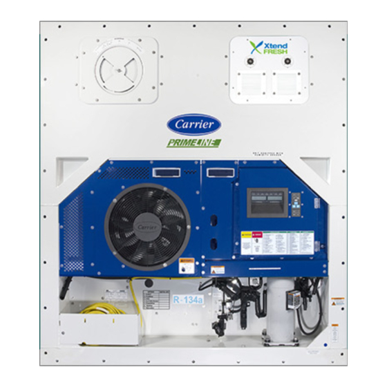
- Page 1 Container Refrigeration OPERATIONS, SERVICE, AND PARTS MANUAL XtendFRESH Controlled Atmosphere Option T-366 Rev G...
- Page 3 OPERATIONS, SERVICE, AND PARTS MANUAL XtendFRESH Controlled Atmosphere Option © Carrier Corporation, 2018 Printed in U. S. A. September 2018...
-
Page 5: Table Of Contents
Solenoid Valves Not Opening Air Vent(s) ....... 5–4 5.2.2 XtendFRESH Fan(s)/XtendFRESH Scrubber Not Operating ....5–5 5.2.3 Heater(s) Not Operating . - Page 6 XTENDFRESH ACCESS PANEL ..........6–6 6.6.1 Removing the XtendFRESH Access Panel ......6–6 6.6.2 Re-installing the XtendFRESH Access Panel .
- Page 7 Figure 6.1 XtendFRESH Panel ........
- Page 8 LIST OF TABLES TABLE NUMBER Page Table 6–1 Maintenance Schedule ............6–1 T-366...
-
Page 9: Safety Summary
CAUTION - alert to potential hazard or unsafe practice that could result in minor personal injury, product or prop- erty damage. The following safety statements are applicable to the XtendFRESH option unit used with any container unit and appear elsewhere in this manual. These recommended precautions must be understood and applied during opera- tion and maintenance of the equipment covered herein. - Page 10 WARNING In case of electrical fire, open circuit switch and extinguish with CO (never use water). WARNING Potential hazardous atmosphere and low oxygen levels inside the container, ventilate before entering. Stay away from doors while venting. Refer to Section 4.7. WARNING Before servicing the unit, make sure the Start-Stop switch (ST) is in the OFF position.
-
Page 11: Introduction
This manual is to be used in conjunction with the separately bound Operation and Service Manual and Service Parts Manual for the model of your particular refrigeration unit. Carrier Transicold’s exclusive XtendFRESH option is a modular system. The XtendFRESH system’s ability to con- trol container atmosphere is done by removing ethylene and simultaneously controlling levels of O and CO . -
Page 13: Description
XtendFRESH Control Box 3.1.2 Evaporator Section Components of the XtendFRESH option are mounted in the evaporator section in addition to the standard refriger- ation unit components. These components (Figure 3.2) include the XtendFRESH Scrubber Assembly, Motor Assembly and Sensor Package. -
Page 14: Figure 3.2 Evaporator Section Components
Figure 3.2 Evaporator Section Components Scrubber Assembly Sensor Package Motor Assembly 1. Scrubber Filter Assembly 7. Sensor Air Filter 2. Desorb Out Hose 8. O Amplifier 3. CO Scrubber Motor 9. Desorb In Hose 4. O Sensor 10. O Inlet 5. -
Page 15: Operation
Section 6.10. XTENDFRESH OPERATION There are two function codes, Code 43 and Code 44, that assist with XtendFRESH operation. Code 43 contains specific parameters for operation and Code 44 provides a visible display of component conditions. CODE 43 (CD43) Cd43 is used to select a specific mode of operation and the associated parameters. The modes of operation are: FrESh, OFF, and tESt. -
Page 16: Make Off Mode Active
Make Off Mode Active When OFF mode is active, all XtendFRESH operations will be disabled. The XtendFRESH vents will be closed and the scrubber will remain off. This will be the default mode anytime a frozen mode of operation has been selected. -
Page 17: Code 44 (Cd44)
It is required that the calibration procedure only be performed during pre-trip or when the con- tainer has been fully vented. CODE 44 (CD44) Cd44 allows the user to view the following XtendFRESH values: CO setpoint, CO per- centage, O... -
Page 18: Container Venting Procedure
CONTAINER VENTING PROCEDURE WARNING Potential hazardous atmosphere and low oxygen levels inside the container, ventilate before entering. Stay away from doors while venting. (Refer to Section 4.7) 1. Set the Start-Stop (ST) switch to the “I” position to turn the unit On. 2. -
Page 19: Troubleshooting
AL07 FRESH AIR VENT OPEN Cause: For units equipped with XtendFRESH and a Vent Position Sensor, the controller will monitor the manual fresh air opening at a pre-determined time. If during this time the fresh air vent is open and XtendFRESH is active, an alarm will be generated. - Page 20 If no part is available, open manual fresh air vent. Component XtendFRESH Fan(s) / XtendFRESH Scrubber Motor Troubleshooting Visually inspect to see if the XtendFRESH Fan(s) are running (air blowing on left, intake on right), check current draw of motor at the XST1 (~40 to 200 milliamps / contactor load side).
- Page 21 Component Scrubber Failure Troubleshooting Refer to the troubleshooting of the Scrubber Motor in the AL29 alarm. Component XtendFRESH Solenoid Valves Troubleshooting Refer to the troubleshooting of the Solenoid Air Vent in the AL29 alarm. Component Container Air Tightness Troubleshooting Seal container where possible (access panels, rear doors, mounting hardware, etc).
-
Page 22: Xtendfresh Assembly Not Operating
XTENDFRESH ASSEMBLY NOT OPERATING 5.2.1 Solenoid Valves Not Opening Air Vent(s) Cd43 run Solenoid Valves “Test” Mode Not Opening Operation Vents Normal Open Check Fuse FX4 in XF Control Box Check wiring Does the XF connections to Check wiring for... -
Page 23: Xtendfresh Fan(S)/Xtendfresh Scrubber Not Operating
5.2.2 XtendFRESH Fan(s)/XtendFRESH Scrubber Not Operating XtendFRESH Fan(s) or Cd43 run XtendFRESH Scrubber “Test” Mode Motor Not Operating Visually Operation Check Fuse check Fan(s)/ FX6 in Reefer Normal Motor are Control Box turning Check Fuse Check wiring for Fuse is... -
Page 24: Heater(S) Not Operating
5.2.3 Heater(s) Not Operating Heater(s) Are Not Open XtendFRESH Operating Control Box Cd43 run “Test ” Mode Check Does current draw XH Contactor from top of XH energize? Contactor Operation Check Fuses Current Draw Normal FX5 and FX6 1 amp? -
Page 25: Service
SECTION 6 SERVICE WARNING Before servicing unit, make sure the Start-Stop switch (ST) is in the OFF position. Unit circuit breaker (CB-1) and external power sources are turned OFF and tagged to prevent accidental energizing of circuits. WARNING Potential hazardous atmosphere and low oxygen levels inside the container, ventilate before entering. -
Page 26: Replacing The Panel Air Filter(S)
Figure 6.1 XtendFRESH Panel Louvered Panels 2. Loosen two #10-32 nuts that secure the brackets holding the air filter in place. 3. Slide the panel air filter(s) out (Figure 6.2). Figure 6.2 Panel Air Filter(s) 6.2.2 Replacing the Panel Air Filter(s) 1. -
Page 27: Sensor Air Filter
SENSOR AIR FILTER Figure 6.3 CO Assembly Amplifier Outlet Sensor Sensor Inlet Sensor Air Filter WARNING Potential hazardous atmosphere and low oxygen levels inside the container, ventilate before entering. Stay away from doors while venting. Refer to Section 4.7. WARNING Before servicing unit, make sure the Start-Stop switch (ST) is in the OFF position. -
Page 28: Replacing The Sensor Air Filter Element
1. Follow container venting procedures before performing any maintenance on the sensor air filter element. Refer to Section 4.7. 2. By hand, unscrew and remove the filter cup from the bottom of the sensor air filter assembly (Figure 6.5). 3. Remove the filter element from the filter assembly. 6.3.2 Replacing the Sensor Air Filter Element 1. -
Page 29: Replacing The Oxygen Sensor
Figure 6.6 O Sensor Cushion Clamps O Sensor 6.4.2 Replacing the Oxygen Sensor 1. Install the oxygen sensor by reversing the above steps. CARBON DIOXIDE SENSOR 6.5.1 Removing the CO Sensor When replacing the CO sensor it can be accessed in two ways: through the left-hand side evaporator access panel or through the inside of the container by removing the upper back panel (Figure 6.4). -
Page 30: Xtendfresh Access Panel
(CB-1) and external power sources are turned OFF and tagged to prevent accidental energizing of circuits. 6.6.1 Removing the XtendFRESH Access Panel 1. Remove the two louvered panels from the upper right access panel (Figure 6.1) by removing the mounting bolts and T.I.R locking device if used. -
Page 31: Re-Installing The Xtendfresh Access Panel
6.6.2 Re-installing the XtendFRESH Access Panel 1. Plug in the fresh air solenoid and fan connections, on the back of the access panel. 2. Install the access panel and secure with mounting hardware. 3. Reach into the access panel and pull the transition ducts into position of the access panel. Make sure the gasket is properly seated. -
Page 32: Figure 6.10 Hose/Scrubber Locations
10 degrees to remove it from the unit (Figure 6.11). NOTE Original XtendFRESH units have a tall exhaust port and port cap (Figure 3.2) and need to be removed in order to remove the housing. Figure 6.11 Removing the Scrubber Housing... -
Page 33: Figure 6.12 Scrubber Bolt/Spring Assemblies
Figure 6.12 Scrubber Bolt/Spring Assemblies Bolt and Spring Assembly (4) 7. Separate the upper and lower halves of the scrubber housing. 8. Remove the carbon filter for the scrubber housing along with the gaskets and aluminum seal plate (Figure 6.13). Figure 6.13 Scrubber Separated with Filter Carbon Filter with Gaskets and... -
Page 34: Installing The Scrubber
Figure 6.14 Carbon Filter with Gasket and Seal Plate Orientation Mark Gasket Seal Plate Carbon Filter 10.Place the top plate and gasket on the top of the filter. Align the top housing so that the gasket and aluminum plate fit into the recess in the housing. 11. -
Page 35: Replacing The Scrubber Motor
Figure 6.16 Scrubber Housing 3. Connect the hoses from the air ducts to the scrubber housing (Figure 6.10). 4. Make sure the hose is completely on the housing, tighten the hose clamps and use cable ties to secure the hoses to the gusset. Be sure the hoses are level. 5. -
Page 36: Fresh Air Solenoid
For units equipped with XtendFRESH and a Vent Position Sensor, there is a solid state switch that will change depending on unit operation. If the unit is in XtendFRESH mode (Cd43 set to “FrESH”), the signal provided to the controller will be sent from the Oxygen sensor. If Cd43 is set to “OFF”, the signal to the controller will be sent from the Vent Position Sensor (VPS). -
Page 37: 6.11 Container Preparation
Box Checkout/Leak Test When using the XtendFRESH system, the box must conform to leak rates in order to maintain control of the O setpoints. The minimal box requirement is a pressure decay of 2 inch WG (50mm) to 1 inch WG (25mm) of eight minutes or more for a 40 foot container and four minutes or more for a 20 foot container. -
Page 38: Figure 6.20 Container Leakage Test Ports
Figure 6.20 Container Leakage Test Ports * If ports are not available on Unit then replace Manual Fresh Air panel disc with a disc that has pressure decay ports. (PN: 79-04098-00) Port Location (Not available on all Units) One of the ports is connected to a pressurized air supply and the other is connected to a Magnehelic pressure gauge. -
Page 39: 6.12 Container Curtain
External Checks: Check for leaks with the following recommended checks. Re-pressurize the container to 2 inches water gauge and look for leaks at the following areas using soapy water (mixture of dish detergent and water) looking for bubbles. • Inspect evaporator unit access panels. Check gasket is properly in place. Tighten access panel bolts to 60 inch-lbs. -
Page 40: Installing The Curtain
6.12.1 Installing the Curtain 1. Open the rear doors of the container. 2. Use a new curtain. 3. Fully unfold the door curtain package and hold it up to the container opening. Tape maybe be used to assist holding the curtain in position. 4. -
Page 41: Electrical Wiring Schematic And Diagrams
SECTION 7 ELECTRICAL WIRING SCHEMATIC AND DIAGRAMS INTRODUCTION This section contains the Electrical Schematics and Wiring Diagrams for a basic unit with XtendFRESH Con- trolled Atmosphere option. Refer to the Operation and Service manual for your particular unit for actual schematic and wiring diagram informa- tion on components outside the XtendFRESH option. -
Page 42: Figure 7.1 Pids Nt2570 And Nt2617 - Schematic And Diagram
Figure 7.1 PIDs NT2570 and NT2617 - Schematic and Diagram T-366 7–2... -
Page 43: Figure 7.2 Pids Nt2570 And Nt2617 - Schematic And Diagram
Figure 7.2 PIDs NT2570 and NT2617 - Schematic and Diagram (Page 2) 7–3 T-366... -
Page 44: Figure 7.3 Pids Nt2570 And Nt2617 - Diagram And Legend
Figure 7.3 PIDs NT2570 and NT2617 - Diagram and Legend T-366 7–4... -
Page 45: Figure 7.4 Pids Nt2619 And Nt2704 - Schematic And Wiring Diagram
Figure 7.4 PIDs NT2619 and NT2704 - Schematic and Wiring Diagram 7–5 T-366... -
Page 46: Figure 7.5 Pids Nt2619 And Nt2704 - Schematic And Wiring Diagram
Figure 7.5 PIDs NT2619 and NT2704 - Schematic and Wiring Diagram (Page 2) T-366 7–6... -
Page 47: Figure 7.6 Pids Nt2619 And Nt2704 - Diagram And Legend
Figure 7.6 PIDs NT2619 and NT2704 - Diagram and Legend 7–7 T-366... -
Page 48: Figure 7.7 Pids Nt2709 And Nt2774 - Schematic And Wiring Diagram
Figure 7.7 PIDs NT2709 and NT2774 - Schematic and Wiring Diagram... -
Page 49: Figure 7.8 Pids Nt2709 And Nt2774 - Schematic And Wiring Diagram
Figure 7.8 PIDs NT2709 and NT2774 - Schematic and Wiring Diagram (Page 2) 7–9 T-366... -
Page 50: Figure 7.9 Pids Nt2709 And Nt2774 - Diagram And Legend
Figure 7.9 PIDs NT2709 and NT2774 - Diagram and Legend T-366 7–10... -
Page 51: Service Parts List
All orders and inquiries for parts must include: Parts Identification Number (PID), Model Number, Unit Serial Num- ber, Part Number, Description of part as shown on list and Quantity required. Address all correspondence for parts to the following address: CARRIER TRANSICOLD DIVISION Replacement Components Group, TR-20 P.O. Box 4805, Syracuse, New York 13221... -
Page 52: Parts List For Xtendfresh
9 Parts List for XtendFRESH (Sheet 1 of 2) 6, 7, 9 1, 10, 11, 2, 8, 10 3, 5 4, 5 T-366 9–1... - Page 53 9 Parts List for XtendFRESH (Sheet 2 of 2) Item Part Number Description 79-04124-00 Scrubber Assembly, XtendFRESH 79-04028-20 Scrubber Motor Assembly 58-05136-01 XtendFRESH Hose Desorb 58-05136-00 XtendFRESH Hose Desorb 44-00045-05 Clamp, Hose, 2.06-3.00 Worm Type 68-17663-00 Plate, Cover, .063 Thick Aluminum...
-
Page 54: Parts List For Panel Assemblies
10 Parts List for Panel Assemblies (Sheet 1 of 2) 4, 7, 8 3, 7, 8 2, 7, 8 6, 9, 10, 12 14, 15, 16, 17, 18, 19 XtendFRESH Panel 22, 23, 24 Fresh Air Panel 79-04043 T-366 10–1... - Page 55 Item Part Number Description 79-04043-00 Panel Assembly, XtendFRESH 58-04999-00 Duct, Desorb In 58-05002-00 Duct, Desorb Out 79-04033-00 XtendFRESH Solenoid Valve Assembly 42-00823-00 Gasket 38-00631-00 XtendFRESH Fan 34-00795-09 Nut, Self Lock, 10-32 34-00662-09 Washer, Plain, #10 Medium .032 Thick 34-00662-08 Washer, Plain, #8 Medium .032 Thick...
-
Page 56: Parts List For Panel Assemblies Nt2617 And Up
10 Parts List for Panel Assemblies NT2617 and up (Sheet 1 of 2) 4, 7, 8 3, 7, 8 2, 7, 8 6, 9, 10, 13 15, 16, 17 18, 19, 20 XtendFRESH Panel 23, 24, 25 Fresh Air Panel 79-04086 T-366 10–3... - Page 57 Item Part Number Description 79-04086-01 Panel Assembly, XtendFRESH 58-05002-00 Duct, Desorb In 58-05002-00 Duct, Desorb Out 79-04033-00 XtendFRESH Solenoid Valve Assembly 42-00823-00 Gasket 38-00631-00 XtendFRESH Fan 34-00795-09 Nut, Self Lock, 10-32 34-00662-09 Washer, Plain, #10 Medium .032 Thick 34-00662-08 Washer, Plain, #8 Medium .032 Thick...
-
Page 58: Parts List For Sensor Assembly
11 Parts List for Sensor Assembly (Sheet 1 of 2) 17, 18, 19, 20 17, 20 14, 17 9, 17 3, 4 3, 16 15, 16 5, 6, 7, 8 9, 17 21 24 22, 25 79 04035 T-366 11–1... - Page 59 11 Parts List for Sensor Assembly (Sheet 2 of 2) Item Part Number Description 79-04035-00 Sensor Assembly Includes: 68-17351-00 Plate .090 Thick Aluminum 40-00297-00 Coupling, x Pipe Thread 40-00108-03 Coupling, Half Union 30-00415-01 Sensor Filter Assembly Includes: 30-00415-20 Bowl 30-00415-21 Gasket 30-00415-22 Sensor Air Filter...
-
Page 60: Parts List For Scrubber Assembly
12 Parts List for Scrubber Assembly (Sheet 1 of 2) 7, 8, 10 7, 8, 10 7, 8, 10 8, 9 8, 9 79 04044 T-366 12–1... - Page 61 12 Parts List for Scrubber Assembly (Sheet 2 of 2) Item Part Number Description 48-00468-00 Bottom Housing 48-00469-00 Top Housing 79-04032-00 Scrubber Filter 48-00479-00 Plate, Seal, XtendFRESH 58-04996-00 Gasket, Seal 48-00504-00 Gauge 79-04029-00 Shaft Assembly 24-02028-02 Heater, 230VAC 34-06386-00 Screw, Cap Hex Head HD 34-06099-22 Screw, cap sch, 5/16-18 x 1.75...
-
Page 62: Parts List For Wiring Assembly
13 Parts List for Wiring Assembly (Sheet 1 of 3) 27, 28 15, 16 12, 13, 14 2, 4 4, 23 4, 23 2, 4, 25 18, 19 2, 4, 26 91 00440 T-366 13–1... - Page 63 Wire Tie, 1/16-1-3/4 Self Locking 58-04026-107 Protector 62-10530-41 Label, .75 x .50 “XC1” 62-10530-42 Label, .75 x .50 “XC2” 58-00969-00 Wire Tie, 2.80 Diameter Double Loop 79-04039-00 Door Assembly, XtendFRESH Control Box Includes: 34-06154-03 Screw, Cap Hexhead, T.I.R. 1/4-20 x .75 13–2 T-366...
- Page 64 13 Parts List for Wiring Assembly (Sheet 3 of 3) 34-06053-00 Washer, .250 Inner Diameter x .800 Outer Diameter 34-00665-09 Nut, Hex, #10-32 AU-27JR-131 Washer, Lock, #10 External Tooth 62-03957-04 Decal Warning, High Voltage 42-00776-00 Gasket 22-00060-36 Fuse 15 Amp Slow Blow (Not Shown) 76-66652-00 Fuse Holder (Not Shown) 91-00440...
-
Page 65: 14 Parts List For Motor Assembly
14 Parts List for Motor Assembly 9, 10, 11, 12 79 04028 Item Part Number Description 79-04028-20 XtendFRESH Motor 48-00474-00 Motor Coupling 48-00473-00 Motor Plate 34-00662-09 Washer, Plain #10 Medium .032 Thick 34-60000-20 Screw, Machine Hexhead, M5 x 20mm (.787) -
Page 66: 15 Parts List For Control Box
15 Parts List for Control Box 1, 2, 3, 6, 7 4, 5, 10, 13, 14 Item Part Number Description 22-04043-01 Fuse, 600V 5 Amps 22-04044-01 Fuse Holder, Class CC 22-04044-00 Fuse Block, Class CC, 2 Pole 22-00060-21 Fuse, 5 Amps, Slow Blow (Not Shown) 76-66652-02 Fuse Holder, In-line 34-06243-00... - Page 67 China RoHS per SJ/T 11364-2014 (Pb) (Hg) (Cd) (Cr (VI)) (PBB) (PBDE) SJ/T 11364 GB/T 26572 GB/T 26572 62-66122-03, Rev A T-366...
-
Page 69: Index
INDEX Numerics 34-06386-00 12-2 34-60000-20 14-1 10-00344-01 11-2 34-66627-00 10-2 10-4 10-00398-01 11-2 34-66682-00 10-4 10-00431-00 13-2 38-00631-00 10-2 10-4 10-00431-03 15-1 38-00634-00 10-2 10-4 10-00477-00 15-1 40-00108-03 11-2 10-00495-00 13-2 40-00297-00 11-2 10-00497-00 13-2 40-00640-00 11-2 10-00499-00 15-1 42-00237-00 10-4 10-00502-00 15-1... -
Page 70: Figure 6.6 O2 Sensor
Service, Fresh Air Solenoid 6-12 Service, Pre-Trip 6-12 Carbon Dioxide Sensor 3-1 Service, Scrubber Filter 6-7 CO2 % Service, XtendFRESH Access Panel 6-6 CO2 Scrubber CO2 Sensor CO2 Setpoint Troubleshooting Alarms 5-1 Code 43, Cd43 Troubleshooting, Assembly Not Operating 5-4... - Page 72 Carrier Transicold Division, Carrier Corporation A part of UTC Building & Industrial Systems, a business unit of United P.O. Box 4805 Technologies Corporation. Stock symbol UTX. Syracuse, NY 13221 USA www.carrier.transicold.com...
Need help?
Do you have a question about the XtendFRESH and is the answer not in the manual?
Questions and answers