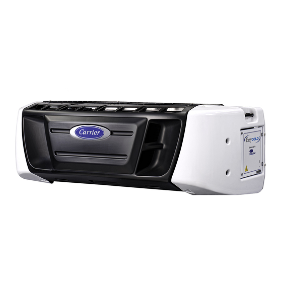
Carrier SUPRA 850Mt Operation And Service Manual

Carrier SUPRA 850Mt Operation And Service Manual

Truck refrigeration unit
Table of Contents

Advertisement

OPERATION AND
OPERATION AND
SERVICE MANUAL
SERVICE MANUAL
TRUCK REFRIGERATION UNIT
750Mt
750Mt
Carrier Transicold Division, Carrier Corporatio
Carrier Tran
SUPRA
SUPRA
, 850Mt , 950Mt
, 850Mt
Carrier Transicold Eur ope -
Carrier Transicold Eur
ope - - 10, Bd de l'O
- 10, Bd de l'O ise -
sicold Division, Carrier Corporation, P.O. Box 4805, Syracuse, N.Y. 13221
 Carrier Refrigeration Operation 2004
 Carrier Refrigeration Operation 2004
© ©
, 950Mt
ise -- 95031 Cergy
- 95031 Cergy Pontoise Cédex
Pontoise Cédex - - - FRAN
n, P.O. Box 4805, Syracuse, N.Y. 13221 U. S.
Printed in Franc e 03-04 / 62-
Printed in Franc
e 03-04 / 62--611XX-
D D
- FRANCE
CE
U. S. A. A.
-611XX--20
-20

Advertisement

Table of Contents
loading

Summary of Contents for Carrier SUPRA 850Mt

  • Page 1 Pontoise Cédex - - - FRAN - FRANCE Carrier Tran Carrier Transicold Division, Carrier Corporatio sicold Division, Carrier Corporation, P.O. Box 4805, Syracuse, N.Y. 13221 n, P.O. Box 4805, Syracuse, N.Y. 13221 U. S. U. S. A. A.  Carrier Refrigeration Operation 2004  Carrier Refrigeration Operation 2004...
  • Page 4 TABLE OF CONTENTS TABLE OF CONTENTS Page Page Section 1 Section 1 S S A A F F E E T T Y Y I I N N S S T T R R U U C C T T I I O O N N S S .
  • Page 5: Table Of Contents

    2.10.1 Use of diagnosis connection of control box (see Figure 2-16) ... . . 2-30 2.10.2 Intervention on generator for analysis ....... . . 2-30 2.11 Refrigerant Circuit .
  • Page 6 ........4-12 4.11 Compressor unloader valve -- For Supra 850Mt  & 950Mt only .
  • Page 7 5.3.6 Abnormal pressure ..........5.3.7 Abnormal noise .
  • Page 8 LIST OF FIGURES Figure 2-1 Supra 750Mt  / 850Mt Models ........Figure 2-2 Supra 950Mt Model .
  • Page 9 LIST OF TABLES Table 2-1 Condensers Model Chart ......... . . Table 2-2 Evaporators Model Chart .
  • Page 10 SECTION 1 SAFETY INSTRUCTIONS This manual contains safety and service instructions to follow in order to prevent any accident. Stickers have been placed on the product for your  SAFETY  . BEFORE USING THIS REFRIGERANT UNIT, readcarefully all safety information explained in this manual and indicated on the product.
  • Page 11 Belts and fans : This refrigeration unit is equipped with Auto--start/stop, it may start at any time and without warning. When the unit is running beware of belts and fans that are moving. Before servicing refrigeration unit, make sure the main power switch is on the OFF position.
  • Page 12 Under no circumstances should anyone attempt to repair the Logic or Display Boards. Should a problem develop with these component, contact your nearest Carrier Transicold dealer for replacement. Under no circumstances should a technician electrically probe the processor at any point, other than the connector terminals where the harness attaches.
  • Page 13 SECTION 2 DESCRIPTION The control system is a microprocessor controller INTRODUCTION (Refer to section 2.8 ). Once the controller ( remoteCab Command within the cab of the truck ) is set at the de- sired temperature, the unit will operate automatically to WARNING maintain the desired temperature within very close lim- its.
  • Page 14: Table 2-1 Condensers Model Chart

    Table 2-1 Condensers Model Chart R-404A Model Engine Compressor Standby Motor SUPRA 750Mt 05K 2 Cylinders 13.6 CT3-44TV SUPRA 850Mt 05K 4 Cylinders refer to section 2.5 c. SUPRA 950Mt 17.2 CT3-69TV 05G 6 Cylinders Table 2-2 Evaporators Model Chart Model Dischar e...
  • Page 15: Figure 2-1 Supra 750Mt _ / 850Mt

    Figure 2-1 Supra 750Mt  / 850Mt Models 1. Muffler 6. Fittings for Mt  evaporators 2. Engine (refer to Table 2-1) 7. Compressor pressure regulating valve (CPR) 3. Compressor (refer to Table 2-1) 8. Filter drier 4. Alternator (12 V) 9. Condenser 5.
  • Page 16 CURBSIDE VIEW 1. -- Battery 6. Fuel filter 11. Receiver sight glass 2. + Micro 7. Speed & Run solenoid 12. Moisture indication sight glass 3. Fuel lines 8. Oil filter 13. Receiver 4. + Battery 9. Oil gauge 5. Serial/Model plate 10.
  • Page 17: Figure 2-2 Supra 950Mt

    Figure 2-2 Supra 950Mt Model 1. Muffler 6. Fitting for Mt  evaporators 2. Engine (refer to Table 2-1) 7. Compressor pressure regulating valve (CPR) 3. Compressor (refer to Table 2-1) 8. Filter drier 4. Alternator (12 V) 9. Condenser 5. Electric standby motor 10.
  • Page 18 CURBSIDE VIEW Silent version Standard version 1. - - Battery 7. Solenoid 12. Moisture indication sight glass 2. + Micro 8. Oil filter 13. Receiver 3. Fuel lines 9. Oil gauge 14. Electrical box 4. + Battery 10. Air cleaner (dry air type) 15.
  • Page 19: Figure 2-3 Evaporator Mts Model

    1. Evaporator Coil 3. RAS Sensor 6. Expansion valve 4. Coil 2. Turbine fan (1, 2 or 3 7. Pressure tap according to the model) 5. Heaters Figure 2-3 Evaporator MTS model...
  • Page 20: Figure 2-4 Evaporator Mtd Model

    1. Evaporator Coil 3. RAS Sensor 6. Expansion valve 4. Coil 2. Turbine fan (1, 2 or 3 7. Pressure tap according to the model) 5. Heaters Figure 2-4 Evaporator MTD model 62--611XX- -20 (03/04)
  • Page 21: Figure 2-5 Electrical Box

    Figure 2-5 Electrical box  1. Capacitors 7. Buzzer 2. Standby motor contactor (MC) 8. Capacitors 3. Motor Overload relay (MOL) 9. Relay and Fuse board 4. Manual run/stop switch 10. Regulation Bypass RBPR relay ( Supra 850 Mt  only ) 5.
  • Page 22: Figure 2-6 Control Relay Board View

    This control relay board allows a better maintenance using pin connections ( TP01 to TP 17 ). With a multimeter, an output voltage can be measured, pin by pin, to check relays power supply. Figure 2-6 Control relay board view FUSE IDENTIFICATION RELAY IDENTIFICATION Rep.
  • Page 23 8,9 liters (9.4 U.S. quarts) not available bypass kit  *  SUPRA 750Mt  : 2200 rpm Operating   High 2250 rpm SUPRA 850Mt  : 2400 rpm pee s 1800 rpm 1800 rpm Injection Setting 140 to 150 kg/cm (1991 to 2133 psi)  * ...
  • Page 24 CPR Setting MODEL bars psig Diesel high speed Diesel low speed SUPRA 750Mt   24,5 ¦ Voltage 230 V 230 V SUPRA 850Mt ¦ Frequency 60 HZ 50 HZ SUPRA 950Mt   27,5 ¦ Speed 2738 rpm 2541 rpm Power...
  • Page 25 STANDBY MOTOR OVERLOAD SETTING MODEL 400V 230V   750 Mt SUPRA 750Mt 11 A 19.2 A SUPRA 850Mt 11 A 20.5 A SUPRA 950Mt 20 A 34.6 A TORQUE VALUES Assembly kg-m ft-lb Power Tray to Frame...
  • Page 26: Table 2-4 Safety Devices

    SAFETY DEVICES System components are protected from damage caused by unsafe operating conditions by automatically shutting down the unit when such conditions occur. This is accomplished by the safety devices listed in Table 2-4. Table 2-4 Safety Devices Unsafe Conditions Safety Device 1.
  • Page 27: Figure 2-7 Cab Command

    2. The Relay Module contains replaceable relays, components, contact your nearest diodes and fuses along with the wiring harness. Carrier Transicold dealer replacement. The Cab Command is remote mounted in the truck. The Cab Command includes the LCD display, keypad and keypad interface (see Figure 2-7).
  • Page 28 The Carrier Transicold microprocessor controller in- Arrows key corporates the following features : The UP ARROW and DOWN ARROW keys are used to alter the set--point. a. Controls supply or return air temperatureto tight lim- Press theup or down arrowkeys untilthe...
  • Page 29 Manual defrost key when switched to (I) the unit and compartment 1 will start in the The MANUAL DEFROST key places the operating mode last entered (cooling unit in a defrost cycle. Under most or heating). conditions it is not necessary to defrost the unit manually as this is done Compartment 2 ON/OFF switch automatically with the air switch or the...
  • Page 30: Table 2-5 Function Parameters

    2.8.5 Digital Display Table 2-5 Function Parameters CODE ENGLISH DATA The digital display has 9 digits. The default display is setpoint on the left and controlled air temperature on DEFR Defrost Interval the right. The readout is keypad selectable for Degrees FN1 ON CITY SPD Low Speed...
  • Page 31 FN4: Standard Units Select For set points at or below --12.2 C (+10 F)  frozen  range  the unit is only considered out-of-range for tem- The standardunit select will control how all parameters peratures above set point. are displayed. The two choices are DEGREES F and DE- GREES C.
  • Page 32: Table 2-7 Unit Data Codes

    default display, the operator would only have to press CD4: Compartment 1 Return Air Temperature the  unit data key    to display the same data again. Compartment 1 Return Air Temperature is displayed with the description 1RA or CD4. The data is displayed Table 2-7 Unit Data Codes with one decimal place and the proper unit designator, CODE...
  • Page 33: Table 2-8 Alarm Display

    CD13: Software Revision 2.8.8 Alarm Display The Eprom software revision number is displayed The fault light (FL) is turned on only for alarms that with the description REV or CD13on the left and Eprom specify it. The default display will be overridden if a softwarerevision number on the right side.
  • Page 34 AL0: Low Oil Pressure Alarm AL8: Starter Motor Alarm The low oil pressure alarm is displayed with the des- The starter motor alarm is displayedwith thedescrip- cription ENG OIL or AL0. This alarm is generated if the tion STARTER or AL8. This alarm is generated if the control senses low oil pressure under the proper condi- starter motorinput signal is not present with starter sole- tions.
  • Page 35 AL16: Compartment 3 Return Air Sensor Alarm mes less than --0.3 bars (--5 PSI) for 120 continuous seconds while any compartment is in cool mode and The Compartment 3 return air sensor alarm is dis- while the return air temperature for the cooling compart- played with the description 3RA SENSOR or AL16.
  • Page 36 defrost switch will override this mode and start a new 45  Control panel minute cycle. When defrost override is active, the ap- propriate alarmwillbe indicated. If the run relay isde-en- ergized during defrost, defrost is terminated. 2.8.11 Continuous or Start/Stop Operation Micro units have two basic operating modes : contin- uous or start/stop.
  • Page 37: Figure 2-8 Auto Start Sequence

    on. A 15 secondnull cycle will elapsebefore subsequent e. Variable Glow Time start attempts. The run relay will remain energized until The glow time for the first start attempt will vary in the next starting sequence. duration based on engine coolant temperature and the Before the next starting sequence, the oil pressure engine as follows : alternator auxiliary output is checked to insure that the en-...
  • Page 38: Table 2-10 Battery Voltages

    Protocol. The microprocessor will power up and transmit a HUGHES protocol packet and continue to Table 2-10 Battery Voltages transmit a packet every hour. The microprocessor will transmit in the Carrier, QualComm protocol if a data Message-  Voltage-  ...
  • Page 39: Figure 2-11 Accumulator

    MHV1 and MHV2 are energized then hot gas goes through MHV2 to the serpentine, coil or evaporator. 2.9.5 By- - pass valve (NC) (Supra 850Mt only) 2.9.3 Hot Gas Valves HGV 1, 2 & 3 (NC) Liquid Suction Valves LSV 1, 2 & 3 (NC) Figure 2-12 By--pass valves - - NC The valve is controlled by the micro (MPP2).
  • Page 40: Figure 2-13 Compressor Cylinder Heat Unloader Hot Gas Bypass

    - - water content in the liquid refrigerant by 2. Spring loaded piston type bypass control valve color change of the indicator disc. 3. Spring loaded discharge check valve GREEN means DRY CIRCUIT b. Unloaded Operation  YELLOW means WET CIRCUIT ( in that case , Pressure from the discharge manifold (Figure 2-13, the filter drier must be change ).
  • Page 41: Figure 2-14 Compressor Cylinder Head Loader Hot Gas Bypass

    c. Loaded Operation 2.9.10 Battery charging alternator Discharge pressure bleeds from the discharge man- ifold (Figure 2-14, item 15) through the strainer (9) and CAUTION (8) bleed orifice to the solenoid valve stem (2) chamber and the back of the piston bypass valve (7). With the solenoid valve (1)  de-energized ...
  • Page 42: Figure 2-15 50 Amp Alternator And Regulator

    3. ( Don’t use ) 50 AMP 1. Positive output (B+) 2. Ground Terminal (B- -) 3. Excitation Input (D+) 4. Regulator, Brush Holder and Brushes Figure 2-15 50 Amp Alternator and Regulator 2.10 GENERATOR (SINGLE PHASE ALTERNATOR) ELECTRIC FAN BOARD  AC4/EFB (RED)  AC6/EFB...
  • Page 43 a. Registered fault Registered fault Initial cause of fault Action to be taken Fault finding parts to be checked - - Without load  Apply a battery 4.5V to capacitor terminals. Loss of residual magnetism. Load the alternator and run engine above nominal speed for a few seconds.
  • Page 44: Refrigerant Circuit

    -  Cut out one side of the diodes. 2.11 REFRIGERANT CIRCUIT -  Check those diodes with an ohmeter. -  The diode is conforme if it has an infinite resistance in one direction and a resistance of  2.11.1 Cooling mode 0 in the other. If the resistance is infinite in both directions or if it is at 0 in both directions, when cooling, the unit operates as a vapor compres- the diode is broken.
  • Page 45: Heat And Defrost Mode

    2.11.2 Heat and defrost mode In heat mode, two technologies can be used: Hot gas heating through the hot gas solenoid valves (HGV1, HGV2 & HGV3) or heating by electric heaters in the evaporator.Heating by hot gas is allowed only if no evaporator is in cooling mode.
  • Page 46: Figure 2-17 Cooling Cycle

    1. Compressor 8. Receiver service valve 15. Hot gas valve (HGV) 16. Evaporator 2. High pressure switch (HP) 9. Subcooler 17. Electric heater 3. Discharge service valve 10. Accumulator/Heat exchanger 18. Compressor pressure 4. Main heat valve (MHV) 11. Filter-drier regulating valve (CPR) 5.
  • Page 47 5. 5. 5. 5. 5. 5. 9. 9. 3. 3. 5. 5. 5. 5. 2. 2. 8. 8. 4. 4. 5. 5. 1. 1. 6. 6. 7. 7. 1. 1. Com Compre pressor ssor 8. 8. Receiv Receiver er service service valve valve 15.
  • Page 48: Operation

    SECTION 3 SECTION 3 OPERATION OPERATION 7. 7. Check refrig Check refrigerant leve erant level ( l ( Refer to T Refer to Table 2-1 ). able 2-1 ). PRE-TR E-TRIP IP INS INSPEC PECTION TION 8. 8. Feel filter-dr Feel filter-drier ier.
  • Page 49 3. 3. The microp The microprocess rocessor will energi or will energize glow cycle (len ze glow cycle (length Road Road operation operation of time depends on engine temperature) and start of time depends on engine temperature) and start the engine. the engine.
  • Page 50: Operation With Auxiliary Control Panel

    b. Changing the setpoint 1. Press the MANUAL DEFROST Key. If conditions are required, a defrost cycle will be initiated. The sequence is the same for each compartment. 3.4.2 Operation with auxiliary control panel 1. Start the unit. 1. Start the unit 2.
  • Page 51 RUN. b. Set pre-set setpoint 2. Press Carrier logo and the lock light will be dis- played. The control panel allows the user to pre-set 5 differents temperatures on each compartment.
  • Page 52: Control Circuit Operation

    Perishable : setpoint > -12 C (54 In the frozen range there are two control logic 1. Press the CARRIER logo until the light is off. depending if heat is allowed or not (refer to micro 2. The indicator goes off.
  • Page 53: Table 3-11 Relay Operation - - Microprocessor Controller

    will be energised. These control theHot GasValve in the Speed  : (engine mode only) : when high speed is evaporators. needed, micro will energize SR relay (which controls speed solenoid SCS) via N3 output. Micro Relay Valve HGR1 HGV1 HGR2 HGV2 HGR3 HGV3...
  • Page 54 3.5.3 Supra 950 Mt specific logic 3.5.4 Supra 850 Mt specific logic Supra 950 Mt   units are equipped with a 05G Supra 850 Mt   units are equipped with a 05K4 compressor with one unloader for capacity control. The compressor with one unloader for capacity control.
  • Page 55: Relay Operation

    850 Mt  / 950 Mt - - Voltage supply to standby motor contactor a. CPL Bypass Valve and subsequent motor start is prevented. The valve is controlled by the micro (P2).The valve opens and closes at the values chosen by FN6. Glow plugs are energizedvia GPRrelay (T3output).
  • Page 56: Figure 3-1 Temperature Controller Operating Sequence (Perishable Range)

    On start/stop, the diesel engine PERISHABLE RANGE stops when all compartments are in null. It restarts when any CONTINUOUS & START/STOP one of the compartment reaches HS COOL autorestart preset conditions. +1.5 +1.3 LS COOL +0.8 NULL ˚ Perishable set point > --12 --0.3 --0.5 LS HEAT...
  • Page 57: Figure 3-3 Temperature Controller Operating Sequence (Frozen Range)

    On start/stop, the diesel engine FROZEN RANGE stops when all compartments are in null. It restarts when any CONTINUOUS & START/STOP HS COOL one of the compartment reaches autorestart preset conditions. LS COOL +0.5 ˚ Frozen set point < --12 NULL LS HEAT Electrical heating for...
  • Page 58: Service

    SECTION 4 SERVICE WARNING WARNING Beware of unannounced starting of Before servicing unit, make sure the engine or standby motor caused by the Run-Stop switch is in the STOP unit thermostat or the start/stop cycle. position. Also disconnect the negative battery cable.
  • Page 59: Description Of Service Requirements

    Check refrigerant level. Check engine speed under load - - Supra 750Mt 2200 rpm / 1800 rpm - - Supra 850Mt 2400 rpm / 1800 rpm - - Supra 950Mt 2250 rpm / 1800 rpm Change the fan motor brushes.
  • Page 60: Figure 4-1 Cooling Circuit

    SERVICING ENGINE RELATED 2. Replace coolant COMPONENTS a. Drain coolant by removing lower radiator hose and radiator cap. 4.3.1 Cooling system b. Install hose and fill system with clean, untreated water to which any proprietary radiator cleaner The condenser and radiator assembly is designed should be added (six ounces - - dry 151 grams to one with the radiator located after the condenser coil.
  • Page 61: Figure 4-2 Fuel Filter And Fuel Circuit

    4.3.2 Changing Lube Oil and Lube Oil filters CAUTION CAUTION When changing oil filters, the new filters should be primed with clean oil. if the filters are not primed, the engine Use only ethylene glycol anti-freeze may operate for a period with no oil (with inhibitors) in system as glycol by supplied to the bearings.
  • Page 62: Figure 4-3 Speed And Run Control Solenoids

    a. Checking fuel circuit 5. De-energize the solenoid and verify that :   for STOP SOLENOID : engine shutdowns 1. The engine must run with bleed port slightly immediatly. Otherwise, adjust solenoid position. unscrewed.This indicates that injection pump pressure is greater than 0.1 bars. (If not check for air for SPEED SOLENOID : Speed lever touchs low leakages and clean fuel lines).
  • Page 63: Figure 4-4 Electric Fuel Pump

    a. Single coil solenoid -- for Supra 950Mt 4.3.5 Engine air cleaner a. Inspection Theoiltypeair cleaner, hose andconnections should be inspected for leaks or fractures in the inlet and outlet hoses. A damaged air cleaner or hose can seriously affect the performance and life of the engine. If housing has been dented or damaged, check all connections immediately.
  • Page 64: Servicing Glow Plugs

    - - pulsation frequency high : fuel circuit has b. Shoes wear low pressure drop -- high flow. 1. Observe clutch housing to check - - pulsation frequency low (or null) : high pres- discolouration of the metal surface, sigh that clutch sure drop inside the circuit -- low or zero flow.
  • Page 65: Figure 4-5 Electronic Belt Tension Meter (Part No. 07-60098--00)

    4.4.1 Belt tension gauge 4.4.2 Trapezoidal V-belt  Alternator Standby motor Engine Compressor Generator Supra 750 Mt 1. Engine to compressor v-belt Figure 4-5 Electronic Belt Tension meter 2. Standby motor to alternator v-belt (part no. 07-60098- -00) 3. Standby motor to compressor v-belt 4.
  • Page 66: Alternator V-Belt

    4.4.3 Alternator V-belt 4. Frontseat (close) suction service valve and the refrigerant will be trapped between the compressor a. Make sure negative battery terminal suction service valve and the manual shutoff (King) disconnected. valve. b.  Tension is done by rotation of alternator around its 5.
  • Page 67: Evacuation And Dehydration

    c.   Remove refrigerant using a refrigerant recovery b. The recommended method to evacuate and system and repair any leaks. Evacuate and dehydrate the system is to connect three evacuation dehydrate the unit. (Refer to section4.7) Charge unit hoses (Do not use standard service hoses, as they with refri-gerant.
  • Page 68: Figure 4-7 Dual Vacuum Pump Connections

    Evaporator Coil Condensator Coil Receiver Receiver Service Valve Discharge Service Valve Suction Service Valve Manometer Vaccum Pump Vaccum meter Figure 4-7 Dual Vacuum Pump Connections CHARGING THE REFRIGERANT SYSTEM NOTE It is possible that all liquid may not be pulled into the 4.8.1 Installing a complete charge receiver, as outlined in step d.
  • Page 69: Figure 4-8 Compressors

    REPLACING THE COMPRESSOR Oil level Oil level Oil level 05 K 2 compressor 05 K 4 compressor 05 G compressor 2 Cylinders 4 Cylinders 6 Cylinders Figure 4-8 Compressors a. Removing 2. Attach two lines (with hand valves near vacuum pump) to the suction and discharge service valves.
  • Page 70 4.11 COMPRESSOR UNLOADER VALVE - - FOR necessary. SUPRA 850MT & 950MT ONLY  Backseat suction service valve and connect oil charging hose to port. Crack the service valve andpurge the oil hose at oil pump. Add oil as necessary.
  • Page 71: Figure 4-9 Unloader Solenoid Valve

    2. Verify coil type, voltage and frequency of old and new 4.12 CHECKING AND REPLACING coil. This information appears on the coil housing. FILTER-DRIER 3. Place new coil over enclosing tube, retainer and 2 methods connect wiring. To Check Filter-Drier  c.
  • Page 72 4.14.2 Checki cking ng low low pre pressu ssure re swit switch 1. 1. a. a. Start the unit after having instal Start the unit after having installed a manometer on led a manometer on 4. 4. compressor. compressor. 5. 5. 2.
  • Page 73: Evaporator Coil

    It is recommended to clean the evaporator coil on a It is recommended to clean the evaporator coil on a ensu sure re a a su sucti ction on pr pres essu sure re ab abov ove e the the pr prop oper er CPR re regu gula lar r ba...
  • Page 74 4. 4. 5. 5. Insta Install ll the the new new exp expans ansion ion val valve ve and and equ equali alizati zation on lin line e via ORFS via ORFS con connec nection tion. . Mak Make e sur sure e that o-ring are that o-ring are correctly in place to avoid leaks.
  • Page 75: Table 4-2 Connection Point Voltage

    4.19 MICROPROCESSOR WARNING 4.19.1 Service guidelines NOTE Most electronic components susceptible to damage caused by The erasable, programmable, read only memory electrical static discharge (ESD). In (EPROM) chip (component U3 on the microprocessor logic board) has a window on it which is covered with certain cases, the human body can a label listing the revision level of the software.
  • Page 76: Table 4-3 Microprocessor Configuration

    4.19.2 Microprocessor configuration Hour Meter The hour meter can be set to any value via the serial When replacing a microprocessor it is important to port, if the meter has less then 5 hours on it. This allows check that the configurations are compatible for the unit a replacement microprocessor to be set to the same into which it will be installed.
  • Page 77: Table 4-4 Sensor Resistance (Ats, Dts, Cdt, Ras, Sas & Wts)

    CNF1: Glow time CNF16: Shut down with alternator aux alarm Indicates to the micro which engine is in the system If CNF16 is on, shut down in diesel when alternator and which glow time should be used. auxiliary signal is not present. CNF2: Discharge sensor 4.19.3 Controller sensor checkout...
  • Page 78: Table 4-5 R-404A Temperature-Pressure Chart

    4.19.4 Suction pressure transducer Before installing a new suction pressure transducer it must be calibrated. The calibration will not be performed if the run relay is energized. This prevents the operator from calibrating the unit with the sensor in the system. The reading of the sensor must be at atmospheric pressure (0 psig or 14.7 psi). If the sensor reading is greater than 20 psig (34.7 psi) or less than - -6.7 psig (8 psi) it can not be calibrated.
  • Page 79: Troubleshooting

    SECTION 5 TROUBLESHOOTING CAUTION Under no circumstances should anyone attempt to service the microprocessor ! Should a problem develop with the microprocessor, contact your nearest Carrier Transicold dealer for replacement.   REFERENCE INDICATION / TROUBLE POSSIBLE CAUSES SECTION DIESEL ENGINE 5.1.1...
  • Page 80: Engine Starts Then Stops

      REFERENCE INDICATION / TROUBLE POSSIBLE CAUSES SECTION 5.1.2 Engine starts then stops Engine stops after several Fuel supply restricted Check rotations No fuel in tank Check Leak in fuel system Check Faulty fuel control operation Engine Fuel filter restricted Replace Injector nozzle(s) defective Engine Manual...
  • Page 81: Alternator (Automotive Type)

      REFERENCE INDICATION / TROUBLE POSSIBLE CAUSES SECTION ALTERNATOR (AUTOMOTIVE TYPE)  Alternator fails to charge Limited charging system operating time Check Battery condition Check  Alternator belt loose/broken Loose, dirty, corroded terminals, or broken leads Check/Repair Excessively worn, open or defective brushes Check Open blocking diode Check...
  • Page 82: Unit Operates Long Or Continuously In Cooling

      REFERENCE INDICATION / TROUBLE POSSIBLE CAUSES SECTION 5.3.3 Unit operates long or continuously in cooling Container Hot Load  Allow time to pull down Correct Defective box insulation or air leak Refrigeration system Abnormal pressure 5.3.6 Temperature controller malfunction 5.3.8 Compressor Defective 5.3.4...
  • Page 83: Figure 4-11 Compressor Pressure Regulating Valve

      REFERENCE INDICATION / TROUBLE POSSIBLE CAUSES SECTION Low suction pressure Suction service valve partially closed Open King valve partially closed Open Filter-drier partially plugged 4.12 Low refrigerant charge Expansion valve malfunction 5.3.10 No evaporator air flow or restricted air flow 5.3.9 Excessive frost on coil Check...
  • Page 84: No Evaporator Air Flow Restricted Air Flow

      REFERENCE INDICATION / TROUBLE POSSIBLE CAUSES SECTION 5.3.9 No evaporator air flow restricted air flow Evaporator coil blocked Frost on coil Check Dirty coil 4.16.1 Fan motor(sà malfunction No or partial evaporator air flow V-belt broken or loose Clutch defective Replace Evaporator fan loose or defective Check...
  • Page 85: Standby Motor Malfunction

      REFERENCE INDICATION / TROUBLE POSSIBLE CAUSES SECTION STANDBY MOTOR MALFUNCTION Standby motor fails to start Motor contactor (MC) defective Replace Motor Overload (OL) open Replace motor Improper power supply Oil pressure switch (OPS) open Replace Selector switch (SSW) defective Standby motor starts, then stops Motor Overload (OL) open High amperage draw...
  • Page 86: Extract From Material Safety Data Bulletin

    SECTION 6 EXTRACT FROM MATERIAL SAFETY DATA BULLETIN POE OIL 1. PRODUCT AND COMPANY IDENTIFICATION  CARRIER TRANSICOLD INDUSTRIES 810 route de Paris 76520 FRANQUEVILLE ST PIERRE FRANCE  4. FIRST AID MEASURES EYE CONTACT : flush thoroughly with water. If irritation occurs, call a physician.
  • Page 87 Specific characteristics of the waste at the time of disposal may affect the availability of the above options. The complete data sheets are available in English and French from Carrier Transicold Industries on  request.
  • Page 88: Forane R404A

    FORANE R404A 1. PRODUCT AND COMPANY IDENTIFICATION  CARRIER TRANSICOLD INDUSTRIES 810 route de Paris 76520 FRANQUEVILLE ST PIERRE FRANCE Product name : Forane (R) 404A Product synonym(s) Chemical family : hydrofluorocarbons Chemical formula : CF3CH2F/CF3CH2F/CF3CH3 Chemical name : 1,1,1,2-tetrafluoroethane (HFC-134a)/Pentafluoroethane (HFC-125)/ ...
  • Page 89  4. FIRST AID MEASURES EYE CONTACT immediatly flush with plenty of water. Get medical attention if irritation persists. SKIN CONTACT flush exposed skin with lukewarm water (not hot), or use other means to warm skin slowly. Get medical attention if frostbitten by liquid or if irritation occures. INGESTION not applicable.
  • Page 90 Furthermore, state and local waste disposal require- ments may be more restrictive or otherwise different from federal laws and regulations. The complete data sheets are available in English and French from Carrier Transicold Industries on  request.
  • Page 91: Electrical Schematic Wiring Diagram

    Under no circumstances should ether or any other starting aids be used to start engine. CAUTION Under no circumstances should anyone attempt to repair the Logic or Display Boards! Should a problem develop with these components, contact your nearest Carrier Transicold dealer for replacement. CAUTION Observe proper polarity when installing battery, negative battery terminal must be grounded.
  • Page 92      2      /      1      R      E      L      L      O      R      T      N      O      C      R      O      S      S      E      C      O      R      P      O      R      C      I      M   -   -     m     a     r     g     a      i      d     c      i      t     a     m     e      h...

This manual is also suitable for:

Supra 750mtSupra 950mt

Table of Contents