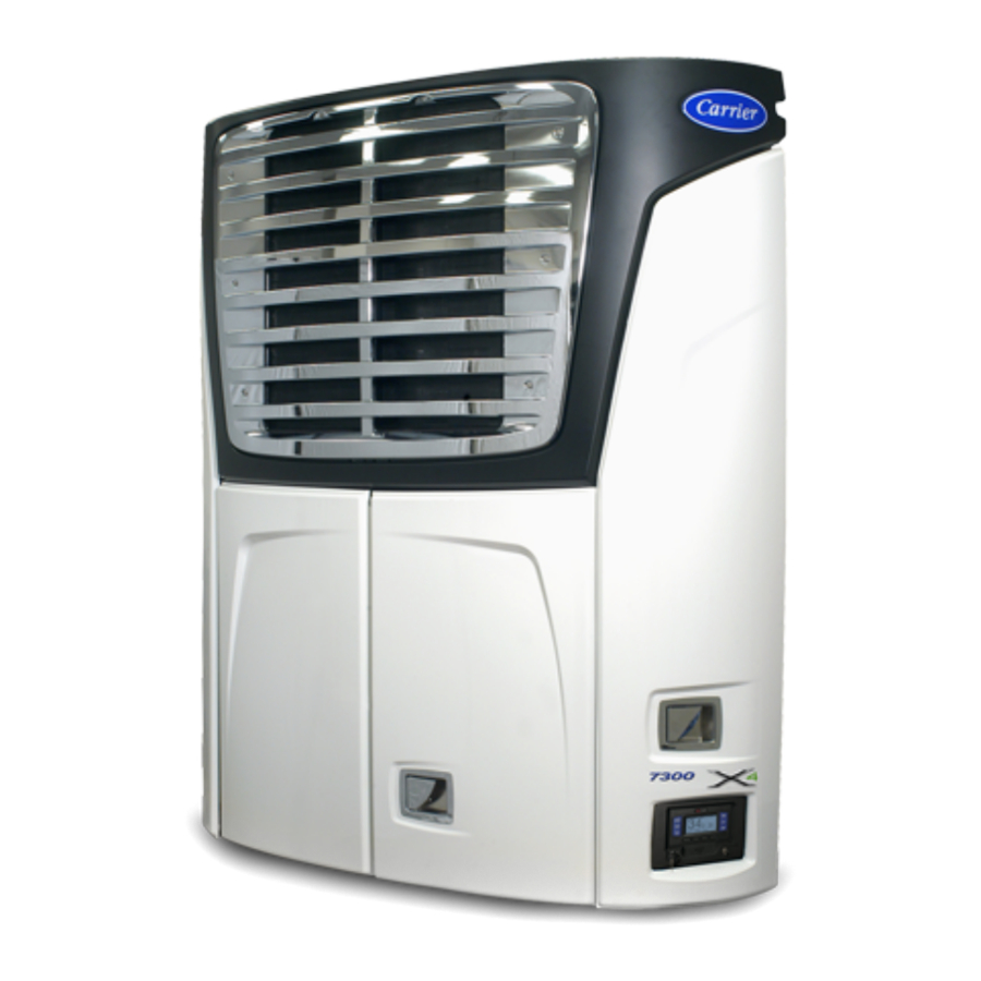
Carrier X4 7300/7500 Trailer & Rail Refrigeration Units Manual
- Operation & service manual (282 pages) ,
- Operator's manual (198 pages) ,
- Operation & service manual (277 pages)
Advertisement
![]()
INTRODUCTION
This guide has been prepared for the operator of a Carrier Transicold X4 7300/7500 Trailer or Rail refrigeration unit with APX Control System. It contains basic instructions for the daily operation of the refrigeration unit as well as safety information, troubleshooting tips, and other information that will help you to deliver the load in the best possible condition. Please take the time to read the information contained in this booklet and refer to it whenever you have a question about the operation of this Carrier Transicold unit.
This refrigeration unit has been engineered to provide long, trouble-free performance when it is properly operated and maintained. The checks outlined in this guide will help to minimize over-the-road problems. In addition, a comprehensive maintenance program will help to insure that the unit continues to operate reliably. Such a maintenance program will also help to control operating costs, increase the unit's working life, and improve performance.
This guide is intended as an introduction to this unit and to provide general assistance when needed. More comprehensive information can be found in the Operation & Service Manual for this unit. This manual can be obtained from your Carrier Transicold dealer.
When having this unit serviced, be sure to specify genuine Carrier Transicold replacement parts for the highest quality and best reliability.
At Carrier Transicold, we are continually working to improve the products that we build for our customers. As a result, specifications may change without notice.
Unit Identification
Each unit is identified by a decal attached to the frame of the unit inside the roadside side door. This decal is on the bottom vertical frame next to the display. The decal identifies the model number of the unit, the warranty ID number, the serial number, the type of refrigerant and refrigerant charge.
If a concern arises, please refer to the information on this decal, and make a note of the model and serial number before calling for assistance. This information will be needed when you contact an authorized Carrier Transicold Dealer so that they may properly assist you.

Nameplate

(SAMPLE)
SAFETY

Unit may start automatically at any time even if the switch is in the OFF position. Use proper lockout/tagout procedures before inspection/servicing. All unit inspection/ servicing by properly trained personnel only.
This Carrier Transicold refrigeration unit has been designed with the safety of the operator in mind. During normal operation, all moving parts are fully enclosed to help prevent injury. During any inspection or servicing with the doors open you may be exposed to moving parts; please stay clear of all moving parts when the unit is in operation.
NOTE TO TECHNICIANS
Refer to the Operation & Service Manual for a complete list of safety precautions.
AUTO-START
This refrigeration unit is equipped with Auto-Start in both Start-Stop and Continuous Operation. The unit may start at any time. A buzzer will sound for 5 seconds before the unit is started. When performing any check of the refrigeration unit (e.g., visually checking belts, checking the oil), place unit in Inspect Mode and disconnect the starter solenoid connector.
COOLING SYSTEM
The engine is equipped with a pressurized cooling system including a pressurized coolant bottle. Under normal operating conditions, the coolant in the engine and radiator is under high pressure and is very hot. Contact with hot coolant can cause severe burns. Do not remove the cap from a hot coolant system; if cap must be removed, cover it with a rag and remove very slowly in order to release pressure without spray.
REFRIGERANT
The refrigerant contained in the refrigeration system of this unit can cause frostbite, severe burns, or blindness when in direct contact with the skin or eyes. For this reason (and because of legislation regarding the handling of refrigerants) we recommend that you contact your nearest Carrier Transicold authorized repair facility whenever service of the refrigerant system is required.
BATTERY
This unit may be equipped with a lead-acid type battery. The battery normally vents small amounts of flammable hydrogen gas. Do not smoke when checking the battery. A battery explosion can cause serious physical harm and/or blindness.
STARTING UNIT

Under no circumstances should ether or any other starting aids be used to start the engine.
Unit may start automatically at any time even if the switch is in the OFF position. Use proper lockout/tagout procedures before inspection/ servicing. All unit inspection/servicing by properly trained personnel only.7
- Place the START/RUN-OFF switch in the START/RUN position.
- The system will display the Carrier Transicold logo, display the default screen, present language selection and the hour meter readings (if configured to do so) along with a test flash of the alarm light. The system will then perform a start sequence, energize the buzzer, and then start the unit automatically.
- If there is an alarm present, the alarm message will be displayed in the MessageCenter and the alarm LED will flash for 5 seconds. If one or more shutdown alarms are present, the alarm(s) must be cleared before the unit will start.
- Observe the MessageCenter. If the word "ACTIVE" or "MODIFIED" is displayed at the right, the unit is equipped with IntelliSet settings; for more information refer to the IntelliSet section of this book.
INSPECT MODE
Inspect Mode provides an additional layer of safety for operators and technicians. Inspect Mode should be used during all pretrip inspections of the unit.
Inspect Mode is a user activated feature that forces the unit to shutdown and remain in shutdown regardless of operating state.
After unit inspection, Inspect Mode must be manually disabled, at which point the unit will resume standard operation.
Inspect Mode is not a substitute for proper Lockout/Tagout procedures, which are always required when servicing the unit.
Enter Inspect Mode:

- With the system powered up (START/RUN-OFF switch in the START/RUN position) press the MENU key until INSPECT MODE is displayed.
- Press the INSPECT MODE soft key, the unit will shut down
While the unit is in Inspect Mode the ALARM light will flash, and the display will indicate that unit operation, including temperature control, has been disabled.
Exit Inspect Mode:

- While the unit is in Inspect Mode, the EXIT soft key will be available, all other keys and functions will be locked out.
- Press the EXIT soft key to disable Inspect Mode, the unit will resume standard operation.
STOPPING UNIT

To stop the unit, place the START/RUN-OFF switch in the OFF position. The refrigeration system and engine will shut down immediately while the control system completes a shut down sequence, and then the display will go blank.
NOTES
The system will close the compressor suction modulation valve (CSMV) and evaporator expansion valve (EVXV) before turning off.
Due to internal processing, turning the START/RUN - OFF switch OFF then back to the START/RUN position will result in a 4 to 50 second delay between the display going off and coming back on again.
Unit may start automatically at any time even if the switch is in the OFF position. Use proper lockout/tagout procedures before inspection/servicing. All unit inspection/ servicing by properly trained personnel only.
EMERGENCY BYPASS MODE
In the event of an alarm caused by a failure of the display module, the refrigeration unit will go into shutdown. In order to temporarily bypass this shutdown state, Emergency Bypass Mode can be activated.
Once Emergency Bypass Mode has been activated, the refrigeration unit will operate normally for 24 hours, a countdown timer will be shown on the display. This 24 hour window of operation will keep the load safe, and provide enough time to contact the nearest Carrier Transicold Service Center for repair of the unit.
Enter Emergency Bypass Mode:

- When the refrigeration unit is in a shutdown state due to the display module alarm, press the MENU key until BYPASS MODE is displayed.
- Press the BYPASS MODE soft key, the unit will resume operation until Emergency Bypass Mode is disabled, or after 24 hours of unit operation in Emergency Bypass Mode.
Exit Emergency Bypass Mode:
- Press the MENU key until the EXIT BYPASS soft key is displayed.
- Press the EXIT BYPASS soft key, the refrigeration unit will shut down. Once Emergency Bypass Mode is turned off, it cannot be restarted and the unit will remain in shutdown until it is repaired.
After repairs have been made and the display module alarm has been cleared, the unit will operate normally and Emergency Bypass Mode will no longer be available.
PRETRIP INSPECTION
The Pretrip Inspection should be performed before picking up any load. This inspection is essential to ensure reliable operation of this unit. These checks take only a few minutes.
Unit may start automatically at any time even if the switch is in the OFF position. Use proper lockout/tagout procedures before inspection/servicing. All unit inspection/ servicing by properly trained personnel only.
| BEFORE STARTING ENGINE |
| Place unit in Inspect Mode and disconnect starter solenoid connector |
| Drain water from bottom of fuel tank |
| Drain water from water separator on fuel filter (if applicable) |
| Check radiator coolant level |
| Check air cleaner indicator |
| Check engine oil level |
| Visually check condition of belts |
| Check door latches & hinges |
| Check battery cables for rubbing or chafing |
| Check battery terminals for cleanliness |
| Check channels or "T" bar floor as well as return air bulkhead for cleanliness and obstruction. Channels and return air bulkhead must be free of debris for proper air circulation. |
| Check air chute |
| Exit Inspect Mode and reconnect starter solenoid connector |
| Start unit and place in continuous operation |
| IMMEDIATELY AFTER STARTING ENGINE |
| Visually check fuel lines and filters for leaks |
| Visually check oil lines and filters for leaks |
| Visually check coolant hoses for leaks |
| Visually check exhaust system for leaks |
| Verify correct air flow of condenser fan* |
| * Place a small rag in front of the condenser coil, the rag should hold. If the rag blows away it means that the fan is rotating in reverse. |
| AFTER 15 MINUTES OF OPERATION |
| Initiate defrost and allow to terminate automatically |
| Check defrost drain line for blockage and proper water flow |
| PRETRIP |
| Initiate Pretrip |
| List any Pretrip alarms |
| FINAL |
| Enter trip start in micro |
GENERAL TROUBLESHOOTING
Unit may start automatically at any time even if the switch is in the OFF position. Use proper lockout/tagout procedures before inspection/servicing. All unit inspection/ servicing by properly trained personnel only.
Everything possible has been done to ensure that this unit is the most reliable, trouble-free equipment available today. If, however you are having an issue, the following section may be of assistance.
If you do not find the trouble that you have experienced listed, please call your Carrier Transicold dealer for assistance.
General Troubleshooting | |
Unit won't crank. | Check alarm list. Visually check battery condition. Visually check battery connections. Check all fuses. |
Unit won't start. | Check alarm list. Check fuel level. Check all fuses. |
Unit won't run. | Check alarm list. Check fuel level. Check engine oil level. Check all fuses. |
Unit stops operating. | Check alarm list. Visually check belts. Check engine oil level. Visually check coolant level. Check fuel level. Check all fuses. |
Unit not cooling/heating properly. | Check alarm list. Initiate Manual Defrost of unit, refer to Manual Defrost section. Check for proper air circulation in the refrigerated compartment. Check condenser for airflow restriction. Check refrigerated compartment for damage or air leaks. |
When replacing fuses, lockout/tagout the negative battery cable.
| Fuse | Purpose | Amps |
| F1 | Module/Buzzer Power | 5A |
| F3 | Engine Control Unit Power | 5A |
| F5 | Power Enable Relay Contact Power | 30A |
| F6 | AutoFresh Air Exchange Solenoid Power | 10A |
| F7 | Main Power | 80A |
| F8 | Fuel Level Sensor Power | 5A |
| F10 | Main Microprocessor Module Component Actuation Power | 20A |
| F11 | Light Bar Power | 5A |
| F12 | Satellite Communications Power | 5A |
| F14 | Fuel Heater Power | 15A |

Unit may start automatically at any time even if the switch is in the OFF position. Use proper lockout/tagout procedures before inspection/servicing. All unit inspection/ servicing by properly trained personnel only.
| SYSTEM | OPERATION |
| a. Pretrip Inspections | |
| |
| b. Every Service Interval or Yearly | |
| Engine |
|
| Fuel System |
|
| Cooling System |
|
| Exhaust System |
|
| Air Intake System |
|
| Starting Circuit |
|
| *Based on EPA 40 CFR Part 89 | |
| Charging Circuit |
|
| Unit |
|
| Refrigeration System |
|
| Electrical System |
|
| c. 5 year or 12,000 H our Maintenance | |
| Coolant System |
|
| d. Oil Change Intervals | |
| Oil Type | Oil Change / ESI Filter Change |
| Petroleum | 3000 hours or 2 years (Maximum oil drain interval is 2 years) |
| Mobile Delvac 1* | 4000 hours or 2 years (Maximum oil drain interval is 2 years) |
| *Mobil Delvac 1 is the only approved synthetic oil | |
These maintenance schedules are based on the use of approved oils and regular pretrip inspections of the unit. Failure to follow the recommended maintenance schedule may affect the life and reliability of the refrigeration unit.
PRIMING FUEL SYSTEM

The mechanical fuel lift pump is mounted on the engine next to the injection pump. This pump has a manual plunger for priming the fuel system when the fuel tank has been run dry.
Keep clear of rotating belts and pulleys.
To prime the fuel system, use the following steps:
- Turn the bleed valve (Red) counter-clockwise until fully opened.
- Turn the top of the manual fuel pump plunger counter-clockwise to unlock it. S-L-O-W-L-Y (up/down once per second) pump the manual plunger until positive pressure (resistance) is felt. This may take up to 200 strokes. Positive pressure indicates fuel flow.
- Continue to pump S-L-O-W-L-Y (up/down once per second) approximately 100 more strokes to fill the filter and bleed the air out of the lines.
- Start engine. It may be necessary to continue to pump until the engine starts.
NOTE:
Running the engine for an extended period of time with the manual plunger up can cause a priming pump failure. - Depress and turn the top of the manual plunger clockwise to lock in place.
- When engine is running smoothly, turn bleed valve clockwise until fully closed.
EMERGENCY ROAD SERVICE
At Carrier Transicold we're working hard to give you complete service when and where you need it. That means a worldwide network of dealers that offer 24−hour emergency service. These service centers are manned by factory trained service personnel and backed by extensive parts inventories that will assure you of prompt repair.
Should you experience a problem with your unit during transit, follow your company's emergency procedure or contact the nearest Carrier Transicold service center. Consult the Shortstop Service Centers directory or visit www.trucktrailer.carrier.com and click on "Dealer Locator" to locate the service center nearest you. The Shortstop directory may be obtained from your Carrier Transicold dealer.
You can also download the Carrier Transicold North America Truck/Trailer Dealer Locator App to your smart phone. The Dealer Locator app provides:
- Location information for every Carrier Transicold dealer in North America
- The nearest dealer from your present location
- Dealer look−up capability
- Dealer services (Trailer, Truck, APU, Mobile Support, etc.)
- Addresses
- Maps to easily find dealers
- Directions and navigation to the dealerships
- Phone number and 24−hour emergency hotlines, where available
- Auto dialing
- Hours of operation
- Link to dealer website
- Ability to add dealers to Contacts
To download the Carrier Transicold North America Truck/Trailer Dealer Locator App, scan this QR code, or go directly to your App store.

If you are unable to reach a service center, call our 24−hour Action Line: (800) 448−1661.
We will do everything we can to get your problem taken care of by an authorized CTD dealer and get you back on the road.
Documents / Resources
References
Download manual
Here you can download full pdf version of manual, it may contain additional safety instructions, warranty information, FCC rules, etc.
Download Carrier X4 7300/7500 Trailer & Rail Refrigeration Units Manual
Advertisement


Need help?
Do you have a question about the Transicold X4 7300 and is the answer not in the manual?
Questions and answers