Table of Contents
Advertisement
This Manual is Bookmarked
Operating Instructions and Parts Manual
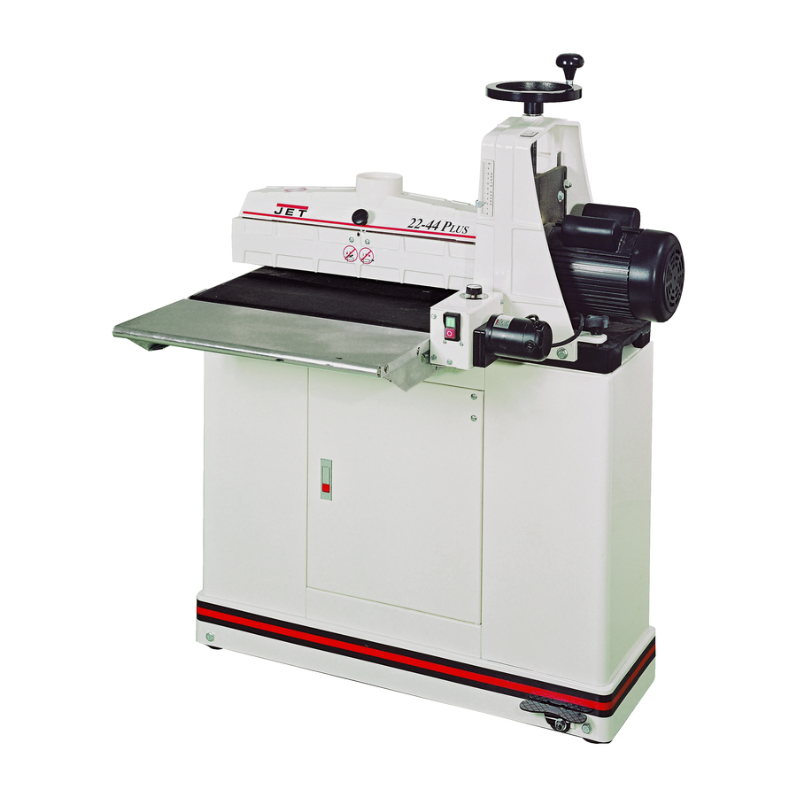
Drum Sander
Model 22-44 Plus
shown with optional infeed-outfeed tables and open stand
WMH TOOL GROUP
2420 Vantage Drive
Elgin, Illinois 60123
Part No. M-649003K
Ph.: 800-274-6848
Revision C 5/06
www.wmhtoolgroup.com
Copyright © WMH Tool Group
Advertisement
Table of Contents
Troubleshooting

Related Manuals for Jet Drum Sander


Summary of Contents for Jet Drum Sander
- Page 1 This Manual is Bookmarked Operating Instructions and Parts Manual Drum Sander Model 22-44 Plus shown with optional infeed-outfeed tables and open stand WMH TOOL GROUP 2420 Vantage Drive Elgin, Illinois 60123 Part No. M-649003K Ph.: 800-274-6848 Revision C 5/06 www.wmhtoolgroup.com...
-
Page 2: Warranty And Service
WARRANTY AND SERVICE WMH Tool Group, Inc., warrants every product it sells. If one of our tools needs service or repair, one of our Authorized Service Centers located throughout the United States can give you quick service. In most cases, any of these WMH Tool Group Authorized Service Centers can authorize warranty repair, assist you in obtaining parts, or perform routine maintenance and major repair on your JET tools. -
Page 3: Table Of Contents
Table of Contents Table of Contents ...3 Warning...4 Introduction...6 Specifications ...6 Features and Terminology ...7 Unpacking ...8 Contents of the Shipping Container ...8 Assembling the Open Stand (Optional Accessory) ...9 Casters (Optional Accessory) ...9 Assembly...10 Installing Drum Head...10 Installing Conveyor Table ...10 Infeed and Outfeed Tables (Optional Accessory)...10 Dust Cover...11 Dust Collection...11... -
Page 4: Warning
5. Do not use this sander for other than its intended use. If used for other purposes, WMH Tool Group disclaims any real or implied warranty and holds itself harmless from any injury that may result from that use. - Page 5 29. Keep your hands clear when feeding parts onto the conveyor. The part will be forced down as it begins to feed, causing a pinching action between the part and the conveyor bed. Never reach into a running machine. Turn off sander and disconnect from power before attempting to retrieve parts from beneath the drum.
-
Page 6: Introduction
This manual is provided by WMH Tool Group covering the safe operation and maintenance procedures for a JET Model 22-44 Plus Drum Sander. This manual contains instructions on installation, safety precautions, general operating procedures, maintenance instructions and parts breakdown. This machine has been designed and constructed to provide years of trouble free operation if used in accordance with instructions set forth in this manual. -
Page 7: Features And Terminology
Features and Terminology The illustration below shows the major components and features of the 22-44 Plus Sander. These are referenced throughout the manual and will help to familiarize you with the operation and functions of the machine. Figure 1... -
Page 8: Unpacking
Read the instruction manual thoroughly for assembly, maintenance and safety instructions. Contents of the Shipping Container Refer to Figure 2 Box 1: Drum Sander Handwheel TUF Tool Abrasive Strip (already installed on drum) Owner’s Manual (not shown) Warranty Card (not shown) Hardware Bag containing: 4 Socket Head Cap Screws, 5/16”-18x3/4”... -
Page 9: Assembling The Open Stand (Optional Accessory)
Assembling the Open Stand (Optional Accessory) (Refer to Figure 3. If further clarification is needed, consult the parts breakdown on page 35.) Tools required for Stand assembly: Ratchet wrench with 1/2” socket 1. Assemble legs (H) to outside of Short Rails (L) using carriage bolts (N) and flanged lock nuts (O). Finger tighten only. -
Page 10: Assembly
1 Set of Hex wrenches 1 Adjustable wrench Installing Drum Head The drum sander must be bolted down to a workbench or stand. If you purchased one of the JET stands, place the sander base on the stand and align the holes. Secure the sander to the stand using four 3/8”... -
Page 11: Dust Cover
Proper attachment of the abrasive strip to the drum is critical to achieving top performance from your drum sander. Abrasive strips do not have to be pre-measured. The end of the roll is first tapered and attached to the left (outboard) side of the drum. - Page 12 8. You can use your fingers to work the infeed take-up fastener, but it will be more convenient to use the TUFTool supplied with your sander. Hold the TUFTool with the red end pointing away from you (Figure 12) and insert its hook into the outside hole of the fastener lever (see Figure 14).
-
Page 13: Grounding Instructions
Repair or replace a damaged or worn cord immediately. As received from the factory, your drum sander is intended for use on a 20 amp, 110V dedicated circuit, which has an outlet and a plug that look like the ones illustrated in Figure 15. -
Page 14: Extension Cords
One revolution of the handwheel moves the drum approximately 1/16”. Switch Lockout Unauthorized use of the sander can be prevented by pulling out the key (Figure 18). Press switch to OFF position before removing the key. When the key is removed, the drum can not be started. -
Page 15: Conveyor Belt Tension And Tracking
IMPORTANT: The conveyor belt has been over- tensioned for the purpose of shipping. Before operating the sander, adjust the belt tension according to the following instructions! Tension. To adjust the tension of the conveyor belt, first adjust the take-up screw nut (A, Figure 20) using the attached wrench (B, Figure 20). -
Page 16: Checking Drum Alignment
First inspect the alignment with a gauge of some kind. The following procedure uses a steel straight edge as a gauge. 1. Unplug sander from power source. 2. Open the dust cover and remove the abrasive strip from the drum. -
Page 17: Fine Tuning Drum Alignment
1. Run a piece of scrap wood approximately 6” wide by 30” to 40” long through the sander sideways so that the end of the board extends past the end of the drum. -
Page 18: Tension Roller Alignment
(i.e. those set too high, rendering them non-functional) could allow kick-back of pieces being sanded. 1. Unplug sander from power source and remove abrasive (D, Figure 24) from drum. 2. Loosen all four hex nuts on the bearing bolts (E, Figure 24). -
Page 19: Drum Height Control Adjustment
Setting Depth of Cut Adjusting the drum sander for the proper contact between the abrasive and the stock determines the depth of cut. The depth of cut is controlled by the height adjustment handwheel. -
Page 20: Selecting Sandsmart™ Feed Rates
“Troubleshooting” sections in this manual. Tips for Maximum Performance The versatility designed into the 22-44 Pro drum sander allows it to be used for a wide variety of tasks that will boost the return on your investment. For example, its capabilities range... -
Page 21: Maintenance
Edge Sanding When edge sanding, the sander will mimic the opposite edge of the stock which is lying on the conveyor belt. Because of this, it is important for the stock edge to have been ripped at the proper angle to the face before the sanding process. -
Page 22: Tracker Kit (98-0080)
6. On the underside of the conveyor bed, there are U-channels welded to the bed. The Tracker is positioned on the inside of the first U-channel on the infeed side of sander (the U-channel closest to the rubber covered drive roller and gear motor). The back of the Tracker is magnetized and will stick to the side wall of the conveyor bed. -
Page 23: Abrasives
Abrasives The abrasive material you choose will have a substantial effect on the performance of your sander. Variations in paper type, weight, coating and durability all contribute to achieving your desired finish. JET Abrasives are available in Ready-To- Wrap pre-cut lengths or in the convenient Ready-To-Cut pre-marked box. -
Page 24: Troubleshooting: Motor And Electrical Problems
Adjust tension (see page 15). Allow motor to cool and re-set overload button. Connect sander to a dedicated circuit. Have a certified electrician correct any shop wiring problem. Use a shorter or heavier gauge extension cord (see Figure 17). - Page 25 Trouble Probable Cause Conveyor belt out of adjustment. Drive or driven roller needs adjusting. Conveyor belt tracks Conveyor belt worn or defective. to one side, or oscillates from side to Drive roller worn, bent, or varies in side. diameter side to side. Roller bushings elongated due to excessive wear.
-
Page 26: Troubleshooting: Operational Problems
Ripples in sanded Excessive feed rate. surface. Excessive depth of cut. (Uniformly spaced ripples). Sander vibration. Sniping of wood Tension rollers set too low. (gouging near end of Stock not supported properly during board). infeed or outfeed. Conveyor drive roller or driven roller higher than conveyor belt surface. -
Page 27: Optional Accessories
Trouble Probable Cause Line or groove in Inconsistent feed rate. stock. Unsanded ridge along length of piece Grit has been removed from backing. (sandpaper appears clean). Optional Accessories 609004 Open Stand with Shelf 609005 Closed Stand with Shelf and Casters 98-2202 Infeed/Outfeed Tables 98-0130... -
Page 28: Conveyor And Motor Assembly
Conveyor and Motor Assembly... -
Page 29: Parts List: Conveyor And Motor Assembly
Parts List: Conveyor and Motor Assembly Index No. Part No. Description Size 1...323759... Gear Motor ... 90 Volt DC ... 1 2...72-6014... Strain Relief ..1 3...72-5336... Cord Set ... 110-120V-75”... 1 4...TS-0680031 ... Flat Washer ... 5/16 ... 4 5...10-4010-08... -
Page 30: Drum Head Assembly
Drum Head Assembly... -
Page 31: Parts List: Drum Head Assembly
Parts List: Drum Head Assembly Index No. Part No. Description Size 1...70-4102... Motor, 1-3/4 HP, 110-120 Volt w/Cord..1 1A...70-4102MFC ... Motor Fan Cover..1 2...72-6104... Strain Relief ..1 3...72-5345... Cord, Motor To Control Box ..1 4...30-9025... - Page 32 56 ...11-1000-04... Lock Washer, Internal Tooth ... 1/4”... 2 57 ...12-2000-04... Hex Nut ... 1/4-20 ... 2 58 ...11-1002-04... Flat Washer ... 1/4 ... 2 59 ...12-9001... Nylon Insert Lock Hex Nut ... #6-32 ... 2 60 ...2244PLUS-260... Hex Nut ... 3/8-16 ... 1 61 ...98-0060...
-
Page 33: Parts List: Open Stand - #609004 (Optional Accessory)
Parts List: Open Stand – #609004 (Optional Accessory) Index Part Description Size Qty. 1...40-4040... Leg, Left ..2 2...40-4041... Leg, Right (with TUF tool holder)..2 3...2244PLUS-303... Rail, Long ..2 4...2244PLUS-304... Rail, Short..2 5...2244PLUS-305... Shelf ..1 6...10-1206... -
Page 34: Parts List: Closed Stand - #609005 (Optional Accessory)
Parts List: Closed Stand – #609005 (Optional Accessory) Index No. Part No. Description Size 1...2244PLUS-401... Base ..1 2...JSG96-302... Lock Nut ... 3/8 ... 4 3...PJE-S05... Wheel ..4 4...JSG96-304... Hex Head Screw... 3/8-16x2-1/2 ... 4 5...2244PLUS-405... Shaft..1 6...PJN-S04 ... -
Page 35: Parts List: Infeed And Outfeed Tables - #98-2202 (Optional Accessory)
Parts List: Infeed and Outfeed Tables – #98-2202 (Optional Accessory) Index Part Description Size Qty. 1...2244PLUS-501... Table ..2 2...2244PLUS-502... Base Bracket ..2 3...TS-0060051 ... Hex Cap Screw... 3/8”-16UNC x 1”... 4 4...TS-0680041 ... Flat Washer ... 3/8”... 4 5...2244PLUS-505... -
Page 36: Electrical Connections
Electrical Connections WMH Tool Group 2420 Vantage Drive Elgin, Illinois 60123 Phone: 800-274-6848 www.wmhtoolgroup.com...
Need help?
Do you have a question about the Drum Sander and is the answer not in the manual?
Questions and answers