Table of Contents
Advertisement
Quick Links
Model 352-101, 352-102, 352-103, and 352-104
Division 1 SMART Hazardous Area Telephones
Confidentiality Notice
This manual is provided solely as an operational, installation, and maintenance guide and contains
sensitive business and technical information that is confidential and proprietary to GAI-Tronics. GAI-
Tronics retains all intellectual property and other rights in or to the information contained herein, and
such information may only be used in connection with the operation of your GAI-Tronics product or
system. This manual may not be disclosed in any form, in whole or in part, directly or indirectly, to any
third party.
General Information
GAI-Tronics' Class I, Division 1 SMART Hazardous Area
Telephones are constructed of cast aluminum and are
weatherproof and corrosion resistant. They combine
standard telephone operation with GAI-Tronics' Self-
Monitoring and Reporting Telephone (SMART)
technology to provide optimum performance and
flexibility.
When used with the GAI-Tronics' Telephone
Management Application (TMA) each telephone is
monitored and the status is reported. For complete details,
please refer to the on-line help included with TMA.
This manual applies to the following models:
Model 352-101 Division 1 SMART Hazardous Area
Telephone
Model 352-102 Division 1 SMART Hazardous Area
Telephone with Ring Relay
Model 352-103 Division 1 SMART Hazardous Area
Telephone with Headset
Model 352-104 Division 1 SMART Hazardous Area Telephone with Ring Relay and Headset
GAI-TRONICS 3030 KUTZTOWN RD. READING, PA 19605 USA
V
ISIT WWW
G A I - T R O N I C S ®
A H U B B E L L C O M P A N Y
610-777-1374 800-492-1212 Fax: 610-796-5954
.
-
.
GAI
TRONICS
COM FOR PRODUCT LITERATURE AND MANUALS
Pub. 42004-455B
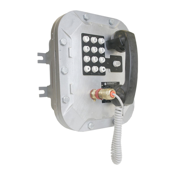
Figure 1. Model 352-101 Division 1
SMART Hazardous Area Telephone
Advertisement
Table of Contents

Related Manuals for GAI-Tronics 352-101


Summary of Contents for GAI-Tronics 352-101
-
Page 1: General Information
Tronics retains all intellectual property and other rights in or to the information contained herein, and such information may only be used in connection with the operation of your GAI-Tronics product or system. This manual may not be disclosed in any form, in whole or in part, directly or indirectly, to any third party. -
Page 2: Installation Guidelines
Model 352-101, 352-102, 352-103, & 352-104 Div. 1 SMART Hazardous Area Telephones Page 2 of 17 The GAI-Tronics SMART Telephone product line provides the flexibility to address a diverse range of applications. A wide variety of functions can be achieved by altering the configuration data stored in the telephone’s non-volatile memory. - Page 3 USE CAUTION when installing or modifying telephone lines. GAI-Tronics’ SMART Telephones are designed to operate on telephone lines as detailed in the “General Information” section of this manual. The telephones are designed to operate with one telephone per line.
-
Page 4: Cable Entries
Pub. 42004-455B Model 352-101, 352-102, 352-103, & 352-104 Div. 1 SMART Hazardous Area Telephones Page 4 of 17 Mounting : The mounting surface must be able to support the weight of the aluminum enclosure, which is 28 lbs. The enclosure must be securely fastened with 3/8-inch diameter steel mounting bolts located on all four mounting feet. -
Page 5: Hardware Description
Hardware Description External Models 352-101 and 352-102 each contain a handset with an approved gland, standard keypad, volume control button, and applicable approval labeling. The handset rests on a cradle, which has a magnetic reed switch located behind it to signal an off-hook condition. The enclosure is sealed with ten cover mounting bolts located around the perimeter of the enclosure’s flange. - Page 6 Pub. 42004-455B Model 352-101, 352-102, 352-103, & 352-104 Div. 1 SMART Hazardous Area Telephones Page 6 of 17 For the Division 1 SMART Telephone models with the headset option, the cradle and handset are replaced with a removable headset and headset activation bracket.
-
Page 7: Ring Relay Pcba
Pub. 42004-455B Model 352-101, 352-102, 352-103, & 352-104 Div. 1 SMART Hazardous Area Telephones Page 7 of 17 Internal With the exception of the ring relay (when fitted), all standard components are mounted to the rear of the front cover. See Figure 6 for the parts layout. - Page 8 Pub. 42004-455B Model 352-101, 352-102, 352-103, & 352-104 Div. 1 SMART Hazardous Area Telephones Page 8 of 17 Wiring WARNING The front cover is not hinged to the rear enclosure. When the cover bolts are removed, the cover must be adequately supported.
- Page 9 Pub. 42004-455B Model 352-101, 352-102, 352-103, & 352-104 Div. 1 SMART Hazardous Area Telephones Page 9 of 17 3. When a Ring Relay PCBA option is present, connect incoming 120 V ac power to the TB1 terminal block. See Figure 8.
-
Page 10: Pcba Hardware Configuration
Pub. 42004-455B Model 352-101, 352-102, 352-103, & 352-104 Div. 1 SMART Hazardous Area Telephones Page 10 of 17 PCBA Hardware Configuration The PCBA hardware configuration options are explained in detail in the following sections and the necessary jumper settings are identified to enable or disable each option. We recommend reading the following sections, recording the desired parameters, and then making the necessary changes. -
Page 11: Auxiliary Outputs
Pub. 42004-455B Model 352-101, 352-102, 352-103, & 352-104 Div. 1 SMART Hazardous Area Telephones Page 11 of 17 Auxiliary Outputs Each telephone includes two isolated solid state switches capable of switching a maximum of 48 V dc, 125 mA or 28 V ac, 80 mA . - Page 12 Pub. 42004-455B Model 352-101, 352-102, 352-103, & 352-104 Div. 1 SMART Hazardous Area Telephones Page 12 of 17 Programming All SMART Telephone models are programmable. The telephone settings are initially programmed during manufacturing and testing. After the SMART Telephone is installed, you have the option of changing the default settings.
- Page 13 Pub. 42004-455B Model 352-101, 352-102, 352-103, & 352-104 Div. 1 SMART Hazardous Area Telephones Page 13 of 17 Basic Programming The following programming command can be entered from any touch-tone telephone. Acceptance of a data transfer command is indicated via a return code transmitted as an audible DTMF tone.
-
Page 14: Operation
Pub. 42004-455B Model 352-101, 352-102, 352-103, & 352-104 Div. 1 SMART Hazardous Area Telephones Page 14 of 17 Operation Models 352-101 and 352-102 Handset Operation 1. Lift the handset to place a call. 2. The handset receiver volume control, which is located on the front cover keypad, can be adjusted to the desired level by pressing the volume control push button. - Page 15 Pub. 42004-455B Model 352-101, 352-102, 352-103, & 352-104 Div. 1 SMART Hazardous Area Telephones Page 15 of 17 Models 352-103 and 352-104 Headset Operation 1. To connect the headset, plug it into the flexible plug on the front of the telephone by removing the sealing cap from the receptacle, aligning the connector pins, and screwing the two ends together.
-
Page 16: Maintenance
Pub. 42004-455B Model 352-101, 352-102, 352-103, & 352-104 Div. 1 SMART Hazardous Area Telephones Page 16 of 17 5. Flip the headset activation bracket to its vertical preset position to hang up. If applicable, place the headset on the bracket after the completion of the call. Otherwise, disconnect the flexible receptacle and plug by unscrewing the two ends, and pulling them apart. -
Page 17: Specifications
Pub. 42004-455B Model 352-101, 352-102, 352-103, & 352-104 Div. 1 SMART Hazardous Area Telephones Page 17 of 17 Specifications TMA Compatibility profile type ..................Type A Handset Electrical Minimum loop current (48 V dc only) ....................20 mA Volume control ..............Five steps (0 dB, 5 dB, 10 dB, 15 dB, 20 dB) Inter-digit pause .......................... -
Page 18: Warranty
Warranty Equipment. GAI-Tronics warrants for a period of one (1) year from the date of shipment, that any GAI-Tronics equipment supplied hereunder shall be free of defects in material and workmanship, shall comply with the then-current product specifications and product literature, and if applicable, shall be fit for the purpose specified in the agreed-upon quotation or proposal document.
Need help?
Do you have a question about the 352-101 and is the answer not in the manual?
Questions and answers