Advertisement
Quick Links
User's
Model 701927
Manual
PBDH0150 Differential Probe
Thank you for purchasing the PBDH0150 Differential Probe (Model 701927). This user's manual
explains the usage, specifications, and handling precautions. To ensure correct use, please read this
manual thoroughly before beginning operation. After reading this manual, keep it in a safe place.
8th Edition: December 2021 (YMI)
All Rights Reserved, Copyright © 2012, Yokogawa Test & Measurement Corporation
Printed in Japan
Notes
•
The contents of this manual are subject to change without prior notice as a result of continuing
improvements to the product's performance and functionality. The figures given in this manual may
differ from those that actually appear on your product.
•
Every effort has been made in the preparation of this manual to ensure the accuracy of its
contents. However, should you have any questions or find any errors, please contact your nearest
YOKOGAWA dealer.
•
Copying or reproducing all or any part of the contents of this manual without the permission of
YOKOGAWA is strictly prohibited.
Conventions Used in This Manual
Improper handling or use can lead to injury to the user or damage to the instrument.
This symbol appears on the instrument to indicate that the user must refer to the
user's manual for special instructions. The same symbol appears in the corresponding
place in the user's manual to identify those instructions. In the manual, the symbol is
used in conjunction with the word "WARNING" or "CAUTION."
WARNING
Calls attention to actions or conditions that could cause serious or fatal injury to the
user, and precautions that can be taken to prevent such occurrences.
CAUTION
Calls attention to actions or conditions that could cause light injury to the user or
cause damage to the instrument or user's data, and precautions that can be taken to
prevent such occurrences.
Note
Calls attention to information that is important for the proper operation of the
instrument.
Safety Precautions
This instrument is designed to be used by a person with specialized knowledge.
The general safety precautions described herein must be observed during all phases of operation.
YOKOGAWA assumes no liability for the customer's failure to comply with these requirements.
In addition, before using the probe, read the manuals of the measuring instrument to thoroughly
familiarize yourself with its specifications and operation.
This manual is part of the product and contains important information. Store this manual in a safe place
close to the instrument so that you can refer to it immediately. Keep this manual until you dispose of
the instrument.
The following symbols are used on this instrument.
Handle with care. Refer to the user's manual or service manual. This symbol appears on
dangerous locations on the instrument which require special instructions for proper handling
or use. The same symbol appears in the corresponding place in the manual to identify those
instructions.
Risk of electric shock
Notes about Usage
Ground the oscilloscope
Make sure to connect the protective grounding terminal of the oscilloscope to ground.
Check grounding
Before connecting the probe input terminal to the circuit under measurement, ensure that the
measuring instrument is grounded properly and that the probe's BNC connector is connected
the oscilloscope input.
Be careful of electric shock
Never use the probe with wet hands or when the probe itself is wet. Doing so may cause
electric shock. Be careful of electric shock when you connect the probe to the circuit under
measurement.
Observe the maximum input voltage
Do not apply voltage exceeding 1400 V (DC + ACpeak) between an input lead and ground or
between two input leads. The maximum input voltage is 1400 V (DC + ACpeak) regardless
of whether 50:1 or 500:1 attenuation is used.
Do not touch exposed circuitry
To prevent injury, do not touch exposed live connections or components.
Connect and disconnect the probe properly
Do not disconnect the probe from the oscilloscope while the probe is connected to the circuit
under measurement. Doing so may cause electric shock.
Do not use in damp places
To prevent electric shock, do not use the probe in damp places.
Do not use in an explosive atmosphere
To prevent fire and injury, do not use the probe in a flammable or explosive atmosphere or
near steam.
Do not disassemble or modify
Do not disassemble or modify the product. YOKOGAWA assumes no liability if you
disassemble or modify the product.
Damaged Signal Cable
If the signal cable is torn and the inner metal is exposed or if a color different from the outer
sheath appears, stop using the cable immediately.
Stop use if you suspect damage
If you suspect that the probe is broken, consult your nearest YOKOGAWA dealer.
IM 701927-01EN
8th Edition
WARNING
•
This product has not been designed or manufactured for applications in which high
reliability is required over a long period of time. This probe is not water or dust resistant.
Do not use the probe in areas with a lot of dust or where water may be spilled.
•
Avoid storing or using the probe in direct sunlight or in areas with high temperature,
humidity, or condensation. Deformation and insulation deterioration can occur causing
the probe to no longer meet the specifications.
•
Avoid vibration, shock, and static electricity during shipping and handling. Take extra care
not to drop the probe.
Operating Environment Limitations
See below for operating environment limitations.
This product is a Class A (for industrial environments) product. Operation of this product in
a residential area may cause radio interference in which case the user will be required to
correct the interference.
1. Overview
The PBDH0150 Differential Probe (Model 701927) is a 150 MHz bandwidth, high-voltage,
differential input probe that is used in combination with DLM series or other digital oscilloscopes that
have the YOKOGAWA probe interface (hereafter referred as oscilloscope with the probe IF).*
To use the probe, simply connect it to a BNC input terminal on an oscilloscope with the probe IF.
Touch the device under measurement with the probe tip to observe the voltage waveform.
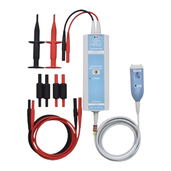
2. Configuration and Part Names
2
Input leads
1
3
Probe interface
Latch release lever
Variable resistor for
adjusting offset voltage
Standard Parts
1. Pincher tips
(Black) B9852MM Long test clip
(Red)
2. Extension leads (1 m)
(Black) B8099LF
(Red)
3. 100 Ω resistance adapters x 2 (yellow) B8099LJ
4. 150 Ω resistance adapters x 2 (green) B8099LK Safety terminal adapter
5. Manuals (see below)
Manual Title
Manual No.
Model 701927
IM 701927-01EN
PBDH0150 Differential Probe
User's Manual
Model 701927
IM 701927-02FR
PBDH0150 Differential Probe
Safety Instructions
Safety Instruction Manual
IM 00C01C01-01Z1 Safety manual (European languages)
Inquiries
PIM 113-01Z2
The "EN", "FR", "Z1" and "Z2" in the manual numbers are the language codes.
Attenuation Switch
Switches between 50:1 and 500:1 attenuation.
Overload Indicator
When the differential input voltage exceeds the following value, the indicator lights.
±140 V (DC + ACpeak) at 50:1 attenuation
±1400 V (DC + ACpeak) at 500:1 attenuation
Probe Interface
The section of the probe that connects to the digital oscilloscope input.
Interface Spring Pins
When the probe interface is connected, these pins touch the pad on the oscilloscope interface
board. The probe's power is supplied through these interface pins. These interface pins are also
used by the oscilloscope to automatically detect the probe attenuation setting.
Latch Release Lever
Releases the lock connecting the probe interface to the oscilloscope input.
Variable Resistor for Adjusting Offset Voltage
You can adjust the offset voltage using an appropriate screwdriver as described below.
Adjustment Screwdriver
Use an adjustment screwdriver that matches the adjustment groove. Using a
W
screwdriver with a large grip or a screwdriver with a small head can damage
the adjustment turn stop or groove.
L
Recommended adjustment driver bit dimensions
Head thickness (W): 0.2 to 0.35 mm; head width (L): 1.3 to 1.5 mm;
head shape: flat or Philips
CAUTION
CAUTION
Overload indicator
Attenuation
Cable
switch
Probe head
O-rings
(8 colors)
Probe interface
To oscilloscope
input
5
4
BNC connector
Interface spring pin
Part No.
Accessories Sold separately
B9852MN Alligator clip (dolphin type)
Fork terminal adapter
B8099LG Alligator clip adapter (rated 300 V) 758922
Alligator clip adapter (rated 1000 V) 758929
Description
This manual
The warnings and cautions in French to
supplement the IM 701927-01EN
List of worldwide contacts
IM 701927-01EN 1/2
Part No.
701906
701954
758921
758931
Advertisement

Related Manuals for YOKOGAWA PBDH0150


Summary of Contents for YOKOGAWA PBDH0150
- Page 1 Avoid vibration, shock, and static electricity during shipping and handling. Take extra care not to drop the probe. Thank you for purchasing the PBDH0150 Differential Probe (Model 701927). This user’s manual explains the usage, specifications, and handling precautions. To ensure correct use, please read this manual thoroughly before beginning operation.
- Page 2 Yokogawa Europe B.V. is the authorized representative of Yokogawa Test & Measurement Corporation Output impedance Used on a 1 MΩ input oscilloscope for this product in the EEA. To contact Yokogawa Europe B.V., see the separate list of worldwide contacts, PIM 113-01Z2. Noise (conversion to input,...
Need help?
Do you have a question about the PBDH0150 and is the answer not in the manual?
Questions and answers